


06/06/2005
Addendum #1 to GEK-39672G
Instructions for making bus connections across shipping split sections
Introduction
PowerVac switchgear is shipped in splits of one, two, three or four stacks. When connecting shipping splits together it may be required to make the connections across the main bus or the tie bus. The main bus can be accessed from the front of the gear through the breaker compartment and the tie bus can be accessed from the rear. Breakers and rollouts should be removed from the switchgear before the bus connections can be made across the shipping split.
This addendum supplements the instructions provided in the main body of the instruction book in pages 28 to 32. Ground bus connections across shipping splits shall be made as specified in page 35 of the instruction book.
WARNING : All primary and secondary circuit devices must be de-energized and the primary circuit grounded before undertaking any work on the switchgear.
Main bus connections across the shipping split
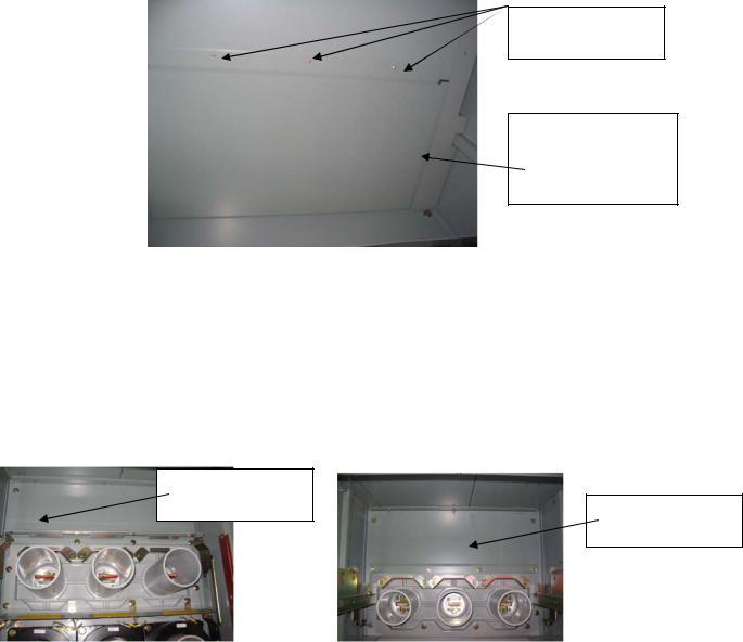
Step – 1, Remove horizontal barrier
A horizontal barrier located between the front upper and lower compartments has to be removed. This barrier is shown in Fig – A(1)-1.
If heaters are provided, the heater shown in Fig – A(1)-1 will have to be removed in order to remove the horizontal barrier.
Do not remove the pan on which the breaker ground shoe is located. Item # 4 in Fig – A(1)-1. In most cases the pan shown as item #4 will have a cover over it ( cover not shown in Fig A(1)-1). It is not required to remove the cover.

|
|
|
(6) Do not remove |
|
|
|
|
|
|
|
|
|
(3) Remove |
|
(5) Do not remove |
|
(later) |
|
|
|
|
|
|
|
|
|
|
|
(2) Remove |
|
(4) Do not remove |
|
|
|
|
|
|
|
|
|
(1) Remove |
|
|
|
heater |
|
|
|
|
|
|
Fig – A(1)-1
Front upper compartment
For stacks that have a 2 High PT/CPT tray in the front upper compartment, the procedure for removing the horizontal barrier is different from that shown above. For such stacks, remove the three taptites ( self threading bolts ) shown in Fig A(1)-2 in the front upper compartment. When these taptites are removed, the barrier underneath shown in Fig –3 can be removed.
Remove these three taptites
Fig A(1) - 2
Front upper compartment intended for 2-High rollouts
51
The underside of the taptites
This barrier can be removed when the 3 taptites are removed.
Fig – A(1)-3
View looking up into the front bottom compartment of a 2 High-A rollout stack
Step – 2, Remove vertical mid barrier in front lower compartment
Remove the vertical mid barrier located in the upper part of the lower front compartment. This barrier is located approximately 49 inch from the front of the stack. See Fig – A(1)- 4a for identification of barrier in the breaker compartment and A(1)-4b for identification of barrier in a PT/CPT rollout compartment
Remove this
barrier Remove this barrier
Fig A(1)-4a |
|
Fig A(1)-4b |
View looking into typical |
|
View looking into typical |
front lower breaker |
|
front lower PT/CPT rollout |
compartment |
|
compartment |
|
|
|
Step – 3, Remove vertical mid barrier in front upper compartment
Remove the vertical mid barrier located in the lower part of the upper front compartment. This barrier is located approximately 49 inch from the front of the stack. See item # 3 of
52

Fig – A(1)-1. Do not remove the secondary disconnect block ( item # 5 ) or the chain ( item # 6 ). This barrier can be removed by sliding it down. This will expose the main bus compartment as shown in Fig – A(1)-5
Tape
Boots
Tape |
|
Copper Main bus or |
|
|
Glastic shipping supt. |
|
|
|
|
|
|
Tape
Fig – A(1)-5
View looking into main bus compartment from the front ( Porcelain inter-unit bus supports )
Step – 4, Remove glastic shipping supports
Unbolt and remove the glastic shipping supports taking care to ensure that splice plates and spacers provided in the bus joint do not fall off. Loosely refasten bus hardware to hold the splice plates and spacers in place. Discard the shipping supports. The red insulating boots will have to be removed to access the bolts for the shipping supports. The boots are held together using plastic re-useable pull-apart fasteners.
Step –5a, Remove inter-unit bus supports ( Go directly to step 5b if polyester glass bus supports are provided)
a)Apply strong adhesive tape so as to keep the two glastic supports together temporarily. The tape may be applied in 4 places – above, below and between the porcelain bus supports. See Fig A(1)-5 and Fig A(1)-6. In Fig A(1)-6, the bus support is shown outside the switchgear to get good picture clarity. It is not required to remove the bus supports out of the switchgear.
b)Remove the ¼ - 20 fasteners used to mount the bus support to the side sheet. There should be 4 ( 2 for poly glass) on the top and 4 ( 2 for poly glass ) at the bottom. The hex nut should be towards the outside on the left hand side of the side sheet.
c)Gently remove the bus support assembly away from the side sheet and into the bus compartment. Let it rest temporarily in a vertical position inside the bus compartment.
53
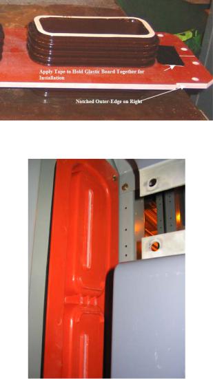
Fig – A(1)-6
Location of tape
Fig A(1)-7
Typical Bus compartment with polyester glass inter-unit bus support
Step – 6 Align switchgear stacks
a)Gently align the next stack on the left with this stack taking care not to damage the porcelain bus supports.
b)When the eight bus support holes ( four holes for polyester glass bus supports ) are aligned, replace the bus support assembly against the side sheet and use the ¼ - 20 hardware to fasten the bus supports and the two side-sheets together as shown in Fig A(1)-8
c)A black rubber gasket is provided to cover the edge of the side sheets around the perimeter of the bus pass-through cutout for 15kV gear. It should be ensured that this gasket is in place.
54
 Loading...