


 Loading...
CPS6000
-48V Indoor/Outdoor Power Shelf
Product Manual
Select Code 167-102-105
Comcode 108992120
Issue 21
January 2008
This document is relevant to the following equipment series:
Controllers: QS840A 1:1 E App version 1.9 and defaults version Std-1.0 QS841A 1:0D App version 1.4.1 and defaults version Std-1.0
Rectifiers: Series
15A QS861A 1:1F
20A QS852A 1:0E
25A QS853A 1:0A
25/30A QS862A 1:1H
40A QS864A 1:0E
50A QS865A 1:1E
Notice:
The information, specifications, and procedures in this manual are subject to change without notice. Lineage Power assumes no responsibility for any errors that may appear in this document.
© 2008 Lineage Power
All International Rights Reserved
Printed in U.S.A.

CPS6000 –48V Indoor/Outdoor Power Shelf
Table of Contents |
|
1 Introduction.............................................................................................................. |
6 |
Overview................................................................................................................... |
6 |
Customer Service Contacts....................................................................................... |
8 |
2 Product Description................................................................................................. |
9 |
CPS6000 System Overview...................................................................................... |
9 |
Block Diagrams ...................................................................................................... |
10 |
Shelf Design............................................................................................................ |
12 |
Configurations......................................................................................................... |
13 |
Distribution and Power Module Configurations..................................................... |
14 |
Battery Reserve System .......................................................................................... |
15 |
Specifications.......................................................................................................... |
16 |
3 Engineering and Ordering .................................................................................... |
24 |
Engineering Information......................................................................................... |
24 |
Ordering Information .............................................................................................. |
26 |
4 Safety....................................................................................................................... |
32 |
Safety Statements.................................................................................................... |
32 |
Warning Statements and Safety Symbols............................................................... |
35 |
Precautions.............................................................................................................. |
36 |
Special Installation Notes ....................................................................................... |
37 |
5 Installation.............................................................................................................. |
39 |
CPS6000 Installation .............................................................................................. |
39 |
Installing the CPS6000 Shelf.................................................................................. |
40 |
Install the CPS6000 Shelf ....................................................................................... |
42 |
Controller ................................................................................................................ |
43 |
QS845A Supplementary Shelf Board ..................................................................... |
45 |
Thermal Compensation Connections...................................................................... |
47 |
Office Alarms.......................................................................................................... |
51 |
Controller Connections ........................................................................................... |
52 |
AC Connections...................................................................................................... |
52 |
C.O. Ground Conductor Installation....................................................................... |
57 |
Rectifier Installation................................................................................................ |
58 |
Ringer Installation................................................................................................... |
59 |
Battery Strings Installation ..................................................................................... |
63 |
Load Connections ................................................................................................... |
67 |
Circuit Breaker and Fuse Installation ..................................................................... |
73 |
Terminate Load Connections - Direct to Bus Connections .................................... |
74 |
Load Connections - Bulk Output ............................................................................ |
75 |
Battery and Load Connections - External DC Distribution Panel .......................... |
76 |
Initial Start-up ......................................................................................................... |
82 |
6 AC, Alarm, and Control Cable Reference Information..................................... |
85 |
Overview................................................................................................................. |
85 |
AC Utility Connection ............................................................................................ |
85 |
Controller Connections ........................................................................................... |
86 |
Issue 21 January 2008 |
3 |

CPS6000 –48V Indoor/Outdoor Power Shelf
Auxiliary Alarms .................................................................................................... |
88 |
Additional Bulk Output Module Connections ........................................................ |
89 |
7A QS840A System Controller ................................................................................ |
90 |
Overview................................................................................................................. |
90 |
CPS6000 Controller Minimum Configuration........................................................ |
96 |
User Interface and Display...................................................................................... |
96 |
Minimum Configuration ......................................................................................... |
96 |
7B QS841A System Controller .............................................................................. |
107 |
Overview............................................................................................................... |
107 |
Status..................................................................................................................... |
116 |
Control/Operations................................................................................................ |
119 |
Configuration ........................................................................................................ |
121 |
10/100 Base-T Ethernet Port................................................................................. |
128 |
8 Rectifier................................................................................................................. |
135 |
Overview............................................................................................................... |
135 |
Alarms and Displays............................................................................................. |
136 |
Features and Functions ......................................................................................... |
138 |
9 QS872A Distribution Monitoring Module......................................................... |
139 |
Overview............................................................................................................... |
139 |
10 Ringer Chassis and Ringers .............................................................................. |
141 |
Ringer Chassis ...................................................................................................... |
141 |
Ringer.................................................................................................................... |
142 |
Types of Ringing................................................................................................... |
143 |
11 Peripheral Devices ............................................................................................. |
146 |
Voltage/Thermal Probes ....................................................................................... |
146 |
Remote Voltage Monitor Module......................................................................... |
147 |
12 ES772A Remote Distribution Module.............................................................. |
149 |
Overview............................................................................................................... |
149 |
Module Features.................................................................................................... |
151 |
Module Connector Definitions ............................................................................. |
152 |
22-position external distribution panel ................................................................. |
159 |
13 Troubleshooting ................................................................................................. |
160 |
Checking for Defective VT-Probes ...................................................................... |
162 |
14 Product Warranty.............................................................................................. |
163 |
Appendix A: T1.317 Command Language ........................................................... |
165 |
Initializing the QS840A Controller....................................................................... |
165 |
T1.317 Command Language................................................................................. |
166 |
Appendix B: Battery Functions ............................................................................. |
190 |
Float Mode............................................................................................................ |
190 |
Slope Thermal Compensation............................................................................... |
190 |
Plant Battery Test.................................................................................................. |
193 |
Boost Mode........................................................................................................... |
194 |
Appendix C: Alarms and Relays ........................................................................... |
197 |
Alarm Relays ........................................................................................................ |
197 |
Alarms................................................................................................................... |
197 |
Appendix D: EasyView for Windows® for the CPS6000 Controller................. |
202 |
Issue 21 January 2008 |
4 |

CPS6000 –48V Indoor/Outdoor Power Shelf
Overview............................................................................................................... |
202 |
Loading the EasyView Application...................................................................... |
202 |
Making the Connection......................................................................................... |
202 |
Configuring a Site................................................................................................. |
203 |
Serial Port Setup ................................................................................................... |
203 |
Connect to Site...................................................................................................... |
203 |
Navigating Once Connected ................................................................................. |
204 |
Appendix E: Pigtail Alarm Cable.......................................................................... |
206 |
Appendix F: Operating Temperature Measurement and Vertical Spacing...... |
209 |
Overview............................................................................................................... |
209 |
Revision History...................................................................................................... |
210 |
Issue 21 January 2008 |
5 |
CPS6000 –48V Indoor/Outdoor Power Shelf
1 Introduction
Overview
CPS6000 -48V Outdoor Power System is a modular power system designed for 19-inch (483mm) and 23-inch (584mm) applications where reliability, space conservation and environmental considerations are critical. This highly dense power system occupies minimum space and its modular architecture enables an exact fit to custom needs.
The shelf architecture is based on the widely accepted and acclaimed CPS4000 systems. AC power is brought in on the left side of the shelf. The first slot on the left side is occupied by the controller. DC Output is aggregated on the right side of the shelf. Rectifiers/Ringers occupy the slots available between the controller and the DC output
Figure 1-1: CPS6000 System with Distribution Module
The CPS6000 currently supports -48V primary loads up to 8.2kW of N+1 redundant power in a single 19-inch shelf, and up to 10.9kW of N+1 redundant power in a 23-inch shelf with a Bulk Output Module and 50A rectifiers.
Issue 21 January 2008 |
6 |

CPS6000 –48V Indoor/Outdoor Power Shelf
CPS6000 systems may include up to 4 bulk-output shelves: an Initial shelf with controller, and up to three supplemental shelves. External distribution is used with multi-shelf systems.
Ringer Chassis may be installed in Power Slots. Each Ringer Chassis supports one ringing output in either non-redundant (simplex) or 1 + 1 redundant (duplex) operation. Ringer distribution is direct from the Ringer Chassis.
The system controller card is powered by the system bus voltage and is located on the left side of the shelf. The controller allows setting of system parameters, and various alarm thresholds locally on the four-line LCD graphics display with intuitive navigation. The controller can perform periodic battery tests and has a provision for user-definable alarm inputs as well as alarm relays.
Applications
CPS6000 fits Outside Plant(OSP) applications, digital loop carrier, remote switch, fiber in the loop, cable television cabinets, Intelligent Vehicle Highway System (IVHS), Personal Communications Service (PCS), cellular, and customer premises applications.
Issue 21 January 2008 |
7 |

CPS6000 –48V Indoor/Outdoor Power Shelf
Customer Service Contacts
Customer Service, Technical Support, Product Repair and Return, and Warranty Service
For customers in the United States, Canada, Puerto Rico, and the US Virgin Islands, call 1- 800-THE-1PWR (1-800-843-1797). This number is staffed from 7:00 am to 5:00 pm Central Time (zone 6), Monday through Friday, on normal business days. At other times this number is still available, but for emergencies only. Services provided through this contact include initiating the spare parts procurement process, ordering documents, product warranty administration, and providing other product and service information.
For other customers worldwide the 800 number may be accessed after first dialing the AT&T Direct country code for the country where the call is originating, or you may contact your local field support center or your sales representative to discuss your specific needs.
Customer Training
Lineage Power offers customer training on many Power Systems products. For information call 1-972-284-2163. This number is answered from 8:00 a.m. until 4:30 p.m., Central Time Zone (Zone 6), Monday through Friday.
Downloads and Software
To download the latest product information, product software and software upgrades, visit our web site at http://www.lineagepower.com/
Issue 21 January 2008 |
8 |

CPS6000 –48V Indoor/Outdoor Power Shelf
2 Product Description
CPS6000 System Overview
CPS6000 power systems are comprised of shelves, rectifiers, ringer chassis, ringers, and distribution modules. Several types of distribution modules are available. The Bulk Output Module provides connection to an external distribution without consuming a shelf power slot.
The CPS6000 is available as single-shelf systems and multiple-shelf systems with both 19inch and 23-inch shelves.
Single Shelf Systems
•With Distribution Module: all components contained in single shelf.
•With Bulk Output Module: uses external distribution, accommodates all other components within the shelf.
Multi-Shelf Systems
•With Bulk Output Module: uses external distribution, accommodates all other components within the shelves.
AC power is supplied to the rectifiers which produce regulated -48V dc output voltage. This voltage is used to power all other system components including ringers, the system controller and the LVD boards. Batteries are connected to distribution, internal or external. Some Distribution Modules provide battery circuit breakers. Single-Slot and Double-Slot Distribution Module options include GMT-style fuses and bullet-style circuit breakers.
Ringer Chassis may be installed in Power Slots. Each Ringer Chassis supports one ringing output in either non-redundant (simplex) or 1 + 1 redundant (duplex) operation. Ringer distribution is direct from the Ringer Chassis. Ringers power ringing signaling outputs and are powered by -48Vdc.
The batteries are monitored by the system controller to ensure their peak performance and longevity against thermal issues. They are monitored via the Voltage/Thermal Probes (VTProbes), which are connected from the Distribution Module to the battery.
The Remote Voltage Monitor (RVM) module may be used with the VT-Probes in making voltage measurements for battery string-voltage imbalance detection. Additional VT-Probes may used by connecting them in a daisy-chain fashion.
The system controller monitors all system parameters and performs battery management functions. It communicates with all devices using the RS-485 bus. The RVM and VT-Probe communicate with the controller using the 1-Wire® from Maxim Integrated Products, Inc.
The LVBD contactor is used to connect the battery strings to the main power bus. Under ac fail conditions, the battery current will be flowing through the contactor to the output distribution in supporting the load. To prevent deep discharge of batteries, the CPS6000 can disconnect the batteries from the load by opening the LVBD contactor.
Issue 21 January 2008 |
9 |

CPS6000 –48V Indoor/Outdoor Power Shelf
CPS6000 also offers an optional low voltage load disconnect (LVLD) contactor. Non-critical loads and loads sensitive to low voltages can be connected to the system via the LVLD in the Distribution Module. CPS6000 disconnects these loads at a set threshold during a battery discharge. This reduces drain on the batteries and extends reserve time available for critical loads.
With the Bulk Output Module, a supplementary shelf may be paralleled to the primary shelf to create a larger plant. Only the primary shelf would contain the system controller. The supplementary shelf only requires signal connections to the primary shelf, and power connections to an external distribution panel. The controller can monitor for open protectors, current from a battery shunt, and monitor and control a low voltage disconnect contactor via the Remote Distribution Module (RDM).
Block Diagrams
2-1a and 2-1b are basic block diagrams of the CPS6000 System in a single shelf with a Distribution Module. Figure 2-2 shows the Bulk Output Module in place of the Distribution Module.
Figure 2-1a: CPS6000 System with Distribution Module
Issue 21 January 2008 |
10 |
CPS6000 –48V Indoor/Outdoor Power Shelf
Figure 2-1b: CPS6000 System with Distribution Module
Issue 21 January 2008 |
11 |

CPS6000 –48V Indoor/Outdoor Power Shelf
Figure 2-2: CPS6000 System with Bulk Output Module
Shelf Design
Features
•The shelf is available in 19-inch (phase 2) and 23-inch standard widths and has the following features:
•Accepts plug-in rectifier, ringer and Distribution Modules.
•19-inch shelves provide 4 Power Slots.
•23-inch shelves provide 5 Power Slots
•Rectifiers, Ringer Chassis, and Distribution Modules may be installed in Power Slots. Permits growth of plant capacity and easy maintenance without service interruption.
Issue 21 January 2008 |
12 |
CPS6000 –48V Indoor/Outdoor Power Shelf
Configurations
The 19-Inch Shelf provides four Power Slots.
The 23-Inch Shelf provides five Power Slots.
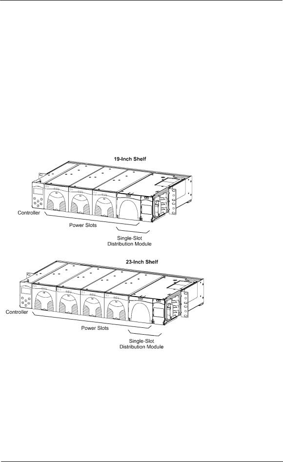
Power Slots support Rectifiers, Ringer Chassis, and Distribution Modules. Figure 2-3 shows the show the locations of the CPS6000 components in the19-inch and 23-inch shelves with the Single-Slot Distribution Module.
Figure 2-3: CPS6000 Systems with Single-Slot Distribution Module
Issue 21 January 2008 |
13 |

CPS6000 –48V Indoor/Outdoor Power Shelf
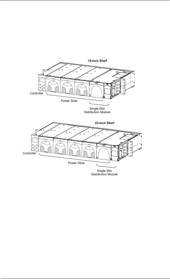
Distribution and Power Module Configurations
The 19-inch shelf has four Power Slots, and the 23-inch shelf has five Power Slots for power modules (Rectifiers and up to two Ringer Chassis) and distribution options (See 2- 4). With Bulk Output Distribution only, all slots are available for power modules. The Single-Slot Distribution Module occupies the right-most Power Slot, and the Double-Slot Distribution Module occupies the right-most two Power Slots, leaving the remaining Power Slots available for power modules. Up to two Ringer Chassis can be installed in the right-most remaining Power Slots.
Figure 2-4: Distribution and Power Module Configurations
Issue 21 January 2008 |
14 |

CPS6000 –48V Indoor/Outdoor Power Shelf
Battery Reserve System
Introduction
A battery reserve system is a key component for a reliable power system. The CPS6000 provides a primary voltage of -48Vdc that drives load equipment. At the same time, it provides float and recharge capability for the battery reserve system. If an ac power failure occurs, the batteries provide power to the load equipment until the ac can be restored.
Types of Batteries
CPS6000 may be used with valve-regulated lead-acid (VRLA) batteries. Up to four strings of VR-type batteries or equivalent general trade batteries may be connected directly to a CPS6000 shelf.
Certain Nickel-Cadmium (Ni-Cd) and Lithium-Ion batteries may also be used with the CPS6000. Please contact your sales representative for details. CPS6000 is also compatible to Flooded lead-acid batteries.
See Appendix D for detailed descriptions of battery related functions; float and boost charging, thermal compensation, and system battery test functions.
Issue 21 January 2008 |
15 |

CPS6000 –48V Indoor/Outdoor Power Shelf
Specifications
Table 2-A: CPS6000 System Specifications
Shelf |
|
Single 19-inch or 23-inch shelf |
|
|
|
|
Power Slots per Shelf |
|
4 (19-inch shelf), 5 (23-inch shelf) |
|
|
|
|
Power Units |
|
|
Max. per |
|
Power Slots |
|
Installed Position5 |
Unit |
|
Shelf |
|
Each |
|
Installed from the Right |
Bulk Output Module |
|
1 |
|
0 |
|
Bulk Output Module |
Single-Slot Distribution Module |
|
1 |
|
1 |
|
Distribution Module |
Double-Slot Distribution Module |
|
1 |
|
2 |
|
Ringer Chassis |
Ringer Chassis |
|
2 |
|
1 |
|
Installed from the Left |
Rectifiers (19-inch shelf) |
|
4 |
|
1 |
|
(23-inch shelf) |
|
5 |
|
1 |
||
|
Rectifiers |
|
|
|
|
|
Rectifier Input Distribution |
|
Dual ac input (19 and 23-inch shelves) |
|
|
|
|
|
|
Individual ac input (19 and 23-inch shelves) |
|
|||
|
|
Single ac input (19 and 23-inch shelves) |
|
|
|
|
System Architecture |
|
Primary output: 1 primary output power bus per shelf |
||||
Primary Power Bus Current |
|
19-inch shelf: 227A |
|
|
|
|
with Bulk Output Module |
|
23-inch shelf: 283A |
|
|
|
|
Output Distribution |
Primary Bus |
Battery connections: double-hole lugs to terminate battery |
||||
|
|
strings. |
|
|
|
|
Bulk Output Module |
-48 Vdc bulk power outputs to loads or distribution |
|
||||
Single-Slot and Double-Slot |
• Bullet-style circuit breakers |
|
|
|
||
Distribution Modules |
• GMT-style fuses |
|
|
|
||
|
|
See Note 2. |
|
|
|
|
Maximum Discharge Current |
|
Based on rectifier capacity. See Note 2 |
|
|
|
|
Maximum Recharge Current |
|
Installed shelf –48V rectifier capacity minus plant –48V load |
||||
Operating Ambient Temperature |
-40 to 75 °C (-40 to 167 °F), see Note 3 |
|
|
|
||
Altitude |
|
-200 to 13,000 feet (-61 to 3962 meters). See Note 4 |
||||
Humidity |
|
10% to 95% non-condensing |
|
|
|
|
Audible Noise |
|
< 60 dBA |
|
|
|
|
Radiated and Conducted Emissions |
FCC Part 15, Class B |
|
|
|
||
|
|
EN55022 (CISPR22), Class B |
|
|
|
|
Harmonics |
|
EN61000-3-2 (IEC61000-3-2) |
|
|
|
|
Voltage Fluctuations |
|
EN61000-3-3 (IEC61000-3-3) |
|
|
|
|
Electromagnetic Immunity |
|
Meets Telcordia GR-1089-CORE |
|
|
|
|
Electrostatic Discharge |
|
EN61000-4-2 Level 3 |
|
|
|
|
RF Immunity |
|
IEC61000-4-3 Level 3, 10 V/m |
|
|
|
|
EFT |
|
IEC61000-4-4 Level 3, No Error; Level 4, No Damage |
||||
Surge |
|
IEC 61000-4-5 Level 3, No Error; Level 4, No Damage |
||||
Conducted Immunity |
|
IEC 61000-4-6 Level 3, 10V |
|
|
|
|
Voltage Dips, Interruptions, and Variations |
IEC 61000-4-11 |
|
|
|
||
Earthquake Rating |
|
Zone 4, upper floors |
|
|
|
|
Safety Agency Approval |
|
Underwriters Laboratories (UL) Listed per Subject Letter 1801: |
||||
|
|
Power Distribution Center for Communications Equipment, and |
||||
|
|
cUL Certified (CSA 22.2 950): Safety of Information |
||||
|
|
Technology Equipment |
|
|
|
|
|
|
VDE licensed to VDE0805/EN60950 |
|
|
|
|
Issue 21 January 2008 |
16 |

CPS6000 –48V Indoor/Outdoor Power Shelf
|
|
|
Rectifiers are individually UL Recognized (UL1950), cUL |
|
|
|
Certified (CSA 22.2 234) or evaluated to EN60950 by an EC |
|
|
|
Notified Body, as appropriate. |
European Economic Community (EEC) |
EMC Directive 89/336/EEC |
||
Directives |
|
|
Low Voltage Directive 73/23/EEC as amended by Marking |
|
|
|
Directive 93/68/EEC |
Note 1: |
CPS6000 can be used with four |
strings of batteries depending on Distribution Module |
|
Note 2: |
When used with Single-Slot and Double-Slot Distribution Modules, maximum output is limited to |
||
|
200A or the size of the LVD contactor installed (if smaller). See Section 3 for limitations on |
||
Note 3: |
maximum currents through Distribution Modules. |
||
Operating temperatures and required airflow are different when used with specific rectifiers. See |
|||
Note 4: |
Tables 2-D through 2-F for rectifier information. |
||
For altitudes above 5000 feet, derate the temperature by 3.6 °F per 1000 feet. For altitudes above |
|||
|
1524 meters, derate the temperature by 0.656 degrees Celsius per 100 meters. |
||
Note 5: |
Power Unit Install Positions: |
|
|
|
• Install these units in order beginning with the right most Power Slot |
||
|
First: |
Distribution Module |
|
|
Second: |
Ringer Chassis |
|
|
• Install these units in order beginning with the left most Power Slot |
||
|
First: |
Rectifiers |
|
Installation Category
CPS6000 is suitable for connection to ac utility systems where the expected level of lightning surges complies with ANSI C62.41 Category B or IEC 60664-1 Overvoltage Category II.
A service entrance surge protector is required in applications where the installation categories can not be classified as being compliant to either ANSI C62.41 Category B or IEC 60664-1 Overvoltage Category II.
CPS6000 rectifiers have been tested for repeated lightning surges typically found in an Overvoltage Category III installation; however, a service entrance surge protector is recommended in cabinet applications to bring the power feeds in compliance to the installation categories above. The service entrance protection should be coordinated with the protection provided in the power modules.
The power module provides common-mode protection via a 320V MOV in series with a 2500V gas-discharge device and differential-mode protection via a 320V MOV in series with a 3.5A fuse.
Issue 21 January 2008 |
17 |

CPS6000 –48V Indoor/Outdoor Power Shelf
Table 2-B: CPS6000 Physical Specifications
|
Height |
Width |
Depth |
Weight |
|
|
in. (mm) |
in. (mm) |
in. (mm) |
lb (kg) |
|
Rectifier |
3.41 (86.6) |
3.4 (86.3) |
11.2 |
(284.5) |
5.75 (2.6) |
Ringer Chassis |
3.41 (86.6) |
3.4 (86.3) |
11.2 |
(284.5) |
3.45 (1.6) |
Ringer |
2.4 (61.0) |
1.51 (38.4) |
9.9 (252) |
1.25 (0.6) |
|
19-Inch Shelf |
3.41 (86.6) |
17.37 (441.2) |
12 (304) – |
7.5 (3.41) |
|
|
|
|
front access |
|
|
|
|
|
13.25 (337)- |
|
|
|
|
|
rear access |
|
|
23-Inch Shelf |
3.41 (86.6) |
20.95 (532.1) |
12 (304) – |
12.7 (5.77) |
|
|
|
|
front access |
|
|
|
|
|
13.25 (337)- |
|
|
|
|
|
rear access |
|
|
Single-Slot Distribution Module |
3.41 (86.6) |
5.1 (129.5) |
12 |
(304) |
9 (4.1) |
Double-Slot Distribution Module |
3.41 (86.6) |
8.5 (216) |
12 |
(304) |
TBM |
Bulk Output Module |
3.41 (86.6) |
1.59 (40.4) |
12 |
(304) |
4 (1.8) |
|
|
|
|
|
|
23-Inch Frame Mounting |
Standard 23 and 26-inch relay racks: |
|
|
||
Requirements |
•Vertical mounting centers: 1.0 in. (25 mm) and 1.75 in. |
||||
|
(44 mm) |
|
|
|
|
|
•Horizontal mounting centers: 22.32 in. (567 mm) |
||||
19-Inch Frame Mounting |
Standard 19-inch relay racks: |
|
|
|
|
Requirements |
•Vertical mounting centers: 1.0 in. (25 mm) and 1.75 in. |
||||
|
(44 mm) |
|
|
|
|
|
•Horizontal mounting centers: 18.31 in. (465 mm) |
||||
Table 2-C: CPS6000 Shelf Specifications |
|
|
|
Control Unit |
QS840A / QS841A |
Nominal Output Voltages |
48/52/54.5 Vdc |
Operating Voltage Range |
42 to 58 Vdc |
Maximum Output Current |
200A per 19-inch shelf; 250A per 23-inch shelf |
(see Note 1) |
|
Nominal Input Voltage |
100/120/200/208/240 Vac |
Input Voltage Ranges |
85 to 275 Vac |
Max Nominal Input Current per Rectifier (based |
13A at 120 Vac |
on 25A rectifier for low line ac, and 50A |
14.5A at 208 Vac |
rectifier for high line ac) |
|
Boost Voltage |
48 to 58 Vdc |
Output Voltage Regulation |
±0.5% |
Output Noise: |
|
Ripple |
100 mVrms maximum, 10 Hz to 20 MHz |
Wideband Noise |
< 250 mV pk-pk over the range dc to 100 MHz |
Load Share Accuracy |
1.5A (maximum) for QS862A |
Maximum Discharge Current |
227A per 19-inch shelf; 284A per 23-inch shelf |
(see Note) |
|
Maximum Recharge Current |
Installed rectifier capacity minus plant load |
Low-Voltage Disconnect |
39 to 50 Vdc |
Low-Voltage Reconnect |
39 to 55 Vdc |
Heat Dissipation |
177W (604 BTU) per QS862A at full load and |
|
120 Vac operation; |
Issue 21 January 2008 |
18 |

CPS6000 –48V Indoor/Outdoor Power Shelf
|
132W (450 |
BTU) per QS861A rectifier at full |
|
load and 120 Vac operation; |
|
|
212W (724 |
BTU) per QS862A at full load and |
|
240 Vac operation; |
|
|
130W (445 |
BTU) per QS861A rectifier at full |
|
load and 240 Vac operation; |
|
|
267W (911 |
BTU) per QS865A rectifier at full |
|
load and 240 Vac operation; |
|
Power Factor |
> 0.98 for loads > 50% of full load |
|
Note: Maximum current is based on Bulk Output Module and 50A QS865A rectifier. System capacity will decrease with lower rated rectifiers.
Power Slots Available for Rectifiers or Ringer Chassis
|
Distribution Module |
|
|
Shelf |
None (Bulk Output Module) |
Single-Wide |
Double-Wide |
19-Inch Shelf |
4 |
3 |
2 |
23-Inch Shelf |
5 |
4 |
3 |
Rectifiers
Table 2-D: QS861A Rectifier Specifications
Nominal Output Voltage |
48/52/54.5 Vdc |
Operating Output Voltage Ranges |
42 to 58 Vdc |
Boost Voltage |
48 to 58 Vdc |
Output Current |
0 to 15A at 54.5V |
Nominal Input Voltage |
100/120/200/208/240 Vac (Shutdown from 135 to |
|
150V) |
Input Voltage Ranges |
85 to 275 Vac |
Input Current |
8A at 120 Vac |
|
4.4A at 208 Vac |
Operating Frequency Range |
45 to 66 Hz |
Operating Temperature |
-40 to +75 °C |
Output Voltage Regulation |
±0.5% |
Output Noise, Ripple |
250 millivolts peak to peak maximum, over the |
|
range dc to 100 MHz |
Load Share Accuracy |
1.5A maximum deviation between rectifiers |
Heat Dissipation (per rectifier, full load) |
132W (450 BTU) at 120 Vac operation |
|
130W (445 BTU) at 240 Vac operation |
Power Factor |
>0.99 (low-line), >0.98 (high line) |
Selective High-Voltage Shutdown |
Above 58 Vdc |
Backup High-Voltage Shutdown |
Above 60 Vdc for 1 millisecond |
Table 2-E: QS852A Rectifier Specifications
Nominal Output Voltage |
48/52/54.5 Vdc |
Operating Output Voltage Ranges |
42 to 58 Vdc |
Boost Voltage |
48 to 58 Vdc |
Issue 21 January 2008 |
19 |

CPS6000 –48V Indoor/Outdoor Power Shelf
Output Current |
0 to 20A at 54.5V |
Nominal Input Voltage |
1200/208/240 Vac |
Input Voltage Ranges |
150 to 275 Vac |
Input Current |
6A at 208 Vac |
Operating Frequency Range |
45 to 66 Hz |
Operating Temperature |
-40 to +75 °C |
Output Voltage Regulation |
±0.5% |
Output Noise, Ripple |
250 millivolts peak to peak maximum, over the |
|
range dc to 100 MHz |
Load Share Accuracy |
1.5A maximum deviation between rectifiers |
Heat Dissipation (per rectifier, full load) |
133 W (454 BTU) at 240 Vac operation |
Power Factor |
>0.98 (high line) |
Selective High-Voltage Shutdown |
Above 58 Vdc |
Backup High-Voltage Shutdown |
Above 60 Vdc for 1 millisecond |
Table 2-F: QS853A Rectifier Specifications
Nominal Output Voltage |
48/52/54.5 Vdc |
Operating Output Voltage Ranges |
42 to 58 Vdc |
Boost Voltage |
48 to 58 Vdc |
Output Current |
0 to 25A at 54.5V (100/120 Vac) |
Nominal Input Voltage |
200/208/240 Vac |
Input Voltage Ranges |
150 to 275 Vac (Shutdown from 135 to 150V) |
Input Current |
7.4A at 208 Vac |
Operating Frequency Range |
45 to 66 Hz |
Operating Temperature |
-40 to +75 °C |
Output Voltage Regulation |
±0.5% |
Output Noise, Ripple |
250 millivolts peak to peak maximum, over the |
|
range dc to 100 MHz |
Load Share Accuracy |
1.5A maximum deviation between rectifiers |
Heat Dissipation (per rectifier, full load) |
212W (724 BTU) at 200 to 240 Vac operation |
Power Factor |
>0.98 for loads > 50% full load |
Selective High-Voltage Shutdown |
Above 58 Vdc |
Backup High-Voltage Shutdown |
Above 60 Vdc for 1 millisecond |
Table 2-G: QS862A Rectifier Specifications
Nominal Output Voltage |
48/52/54.5 Vdc |
|
Operating Output Voltage Ranges |
42 to 58 |
Vdc |
Boost Voltage |
48 to 58 |
Vdc |
Output Current |
0 to 25A at 54.5V (100/120 Vac) |
|
|
0 to 30A at 54.5V (200/240 Vac) |
|
Nominal Input Voltage |
100/120/200/208/240 Vac |
|
Input Voltage Ranges |
85 to 275 Vac (Shutdown from 135 to 150V) |
|
Input Current |
13A at 120 Vac |
|
|
8.8A at 208 Vac |
|
Operating Frequency Range |
45 to 66 |
Hz |
Operating Temperature |
-40 to +75 °C |
|
Output Voltage Regulation |
±0.5% |
|
Issue 21 January 2008 |
20 |
CPS6000 –48V Indoor/Outdoor Power Shelf
Output Noise, Ripple |
250 millivolts peak to peak maximum, over the |
|
range dc to 100 MHz |
Load Share Accuracy |
1.5A maximum deviation between rectifiers |
Heat Dissipation (per rectifier, full load) |
177W (604 BTU) at 100 to 120 Vac operation |
|
212W (724 BTU) at 200 to 240 Vac operation |
Power Factor |
>0.98 for loads > 50% full load |
Selective High-Voltage Shutdown |
Above 58 Vdc |
Backup High-Voltage Shutdown |
Above 60 Vdc for 1 millisecond |
Table 2-H: QS864A Rectifier Specifications (Preliminary)
Nominal Output Voltage |
48/52/54.5 Vdc |
Operating Output Voltage Ranges |
42 to 58 Vdc |
Boost Voltage |
48 to 58 Vdc |
Output Current |
0 to 40A at 54.5V |
Nominal Input Voltage |
200/208/240 Vac |
Input Voltage Ranges |
150 to 275 Vac |
Input Current |
11.8A at 208 Vac |
Operating Frequency Range |
45 to 66 Hz |
Operating Temperature |
-40 to +75 °C |
Output Voltage Regulation |
±0.5% |
Output Noise, Ripple |
250 millivolts peak to peak maximum, over the |
|
range dc to 100 MHz |
Load Share Accuracy |
1.5A maximum deviation between rectifiers |
Heat Dissipation (per rectifier, full load) |
240W (819 BTU) at 240 Vac operation |
Power Factor |
>0.98 for loads > 50% full load |
Selective High-Voltage Shutdown |
Above 58 Vdc |
Backup High-Voltage Shutdown |
Above 60 Vdc for 1 millisecond |
Table 2-I: QS865A Rectifier Specifications |
|
|
|
Nominal Output Voltage |
48/52/54.5 Vdc |
Operating Output Voltage Ranges |
42 to 58 Vdc |
Boost Voltage |
48 to 58 Vdc |
Output Current |
0 to 50A at 54.5V |
Nominal Input Voltage |
200/208/240 Vac |
Input Voltage Ranges |
150 to 275 Vac |
Input Current |
14.5A at 208 Vac |
Operating Frequency Range |
45 to 66 Hz |
Operating Temperature |
-40 to +65 °C |
Output Voltage Regulation |
±0.5% |
Output Noise, Ripple |
250 millivolts peak to peak maximum, over the |
|
range dc to 100 MHz |
Load Share Accuracy |
1.5A maximum deviation between rectifiers |
Heat Dissipation (per rectifier, full load) |
267W (911 BTU) at 240 Vac operation |
Power Factor |
>0.98 for loads > 50% full load |
Selective High-Voltage Shutdown |
Above 58 Vdc |
Backup High-Voltage Shutdown |
Above 60 Vdc for 1 millisecond |
Issue 21 January 2008 |
21 |

CPS6000 –48V Indoor/Outdoor Power Shelf
Table 2-J: QS820A Ringer Specifications
Input Voltage |
|
-40 to -57 Vdc |
See Output VA Thermal Limiting. |
|||
Nominal Input Voltage |
-48 Vdc |
|
|
|||
Input Current |
|
5 A max. |
|
|
||
Output |
ac Component |
65 to 100 Vac |
|
|
||
Voltage |
|
Factory Default: 100Vac |
|
|||
|
|
ac tolerance |
± 5 Vac |
|
|
|
|
|
Regulation |
±5% ac component only |
|
||
|
|
dc Offset |
• -40 to +57 VdcBattery Backed |
|||
|
|
Type of ringing |
• |
+40 to +57 Vdc |
Ground Backed |
|
|
|
• |
0 Vdc Offset Disabled |
|
||
|
|
Battery Backed |
• |
dc Offset tracks dc Input Voltage |
||
|
|
Ground Backed |
• |
Factory Default: Enabled |
||
|
|
Ground Backed no-dc |
||||
|
|
• Battery or Ground Backed is selected by Ringer |
||||
|
|
|
|
Chassis jumper J12 or by external connection of |
||
|
|
|
|
Ring Rtn to Battery or to Ground. Factory Default: |
||
|
|
|
|
Battery Backed by Jumper |
||
|
|
|
See figures in the Ringer section. |
|||
|
|
dc Offset Tracking |
± 3 Vdc |
|
|
|
|
|
Error |
|
|
|
|
|
|
Harmonic Distortion |
5% THD |
|
|
|
|
|
Crest Factor |
1.21 to 1.51 |
|
|
|
Output Frequency |
15 to 50 Hz |
|
|
|||
|
|
|
Factory Default: 20 Hz |
|
||
|
|
Frequency tolerance |
± 1 Hz |
|
|
|
|
|
|
|
|
|
|
Output VA |
|
100 VA |
|
|
||
|
|
Thermal Limiting |
Output VA may be reduced by reducing Vac when |
|||
|
|
|
operating simultaneously above 50°C and less than |
|||
|
|
|
-50Vdc input. |
|
|
|
|
|
|
Vac is reduced only sufficiently to prevent damage to |
|||
|
|
|
the ringer. |
|
|
|
Load Power Factor |
Operating: 0.5 Leading to 0.9 Lagging |
|||||
|
|
|
No Damage: 0 Leading to 0.7 Lagging |
|||
|
|
|
||||
Operating Temperature |
-40 to +75 °C |
See Output VA Thermal Limiting. |
||||
Heat Dissipation |
50 W (170 BTU / hr) |
|
||||
Under Voltage Shutdown |
50% of Output Vac Set Point |
|||||
|
|
|
While shutdown due to external fault, restart will be |
|||
|
|
|
performed at approximately 2 minute intervals. |
|||
Table 2-K: QS840A and QS841A Control Unit Specifications
Operating Input Voltage Range |
38 to 60 Vdc |
Input Power |
6.0 watts maximum |
Plant Parameter Setting |
Through front panel LCD display and menu keys or with |
|
IBM compatible PC with RS-232 port. 841 also has 10/100 |
|
Baset-T network ability |
Alarm Contact Ratings |
60 Vdc, 0.5A, Form-C |
Operating Temperature |
-40 to +75 °C |
Issue 21 January 2008 |
22 |

CPS6000 –48V Indoor/Outdoor Power Shelf
Table 2-L: QS845A Supplementary Board Specifications
Operating Input Voltage Range |
Input power through QS840A or QS841A |
Plant Parameter Setting |
None, communicates with shelf components QS840A/QS841A |
Alarm Contact Ratings |
None |
Operating Temperature |
-40 to +75 °C |
Issue 21 January 2008 |
23 |

CPS6000 –48V Indoor/Outdoor Power Shelf
3 Engineering and Ordering
Engineering Information
Introduction
This section discusses the factors to be considered in determining the number of rectifiers and ringers required in both non-redundant and redundant battery plants.
Rectifier Sizing (Non-Redundant Systems)
In non-redundant systems, the installed rectifier capacity of the battery plant must be sufficient to provide the current required for the load during normal operations as well as the current required to recharge the battery following ac power outages.
For the telecommunications industry, the system load current is known as the average busyhour current. (The average busy-hour current drain is defined as the average busy-hour current drain during busy season with the plant operating at the normal voltage.) Therefore, the minimum installed rectifier capacity (mirc) is the sum of the average busy-hour (abh) current and the required battery recharge current, or
mirc = abh + recharge current
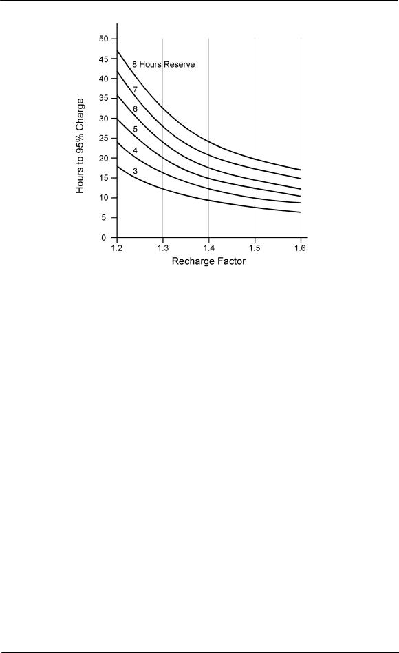
The battery recharge current is determined by two system considerations: the maximum time the system is required to operate in the absence of ac power (reserve time), and the time allocated to recharge the battery after ac power returns. These two times and Figure 3-1 may be used to determine the recharge factor. This factor, when multiplied by the average busyhour current, determines the minimum installed rectifier capacity, or:
mirc = abh x recharge factor
The mirc divided by the individual rectifier capacity determines the number of rectifiers (of equal capacity) required for a non-redundant system.
Rectifier Sizing (Redundant Systems)
In redundant systems, a spare on-line rectifier is included so that the loss of any one rectifier will not cause the available plant capacity to fall below the required minimum installed rectifier capacity. Thus, the loss of a rectifier will not affect the normal system operation nor will it cause the batteries to discharge, and will allow the batteries to recharge in the required time.
In cases where the additional spare rectifier will provide the required battery recharge current, the mirc satisfies the requirements for both non-redundant and redundant systems. In other cases, rectifiers in addition to the redundant rectifier may be required to provide the battery recharge current. Typically, the number of spare rectifiers required for a redundant system is the larger of one spare rectifier or 200% of the rated load.
Issue 21 January 2008 |
24 |
CPS6000 –48V Indoor/Outdoor Power Shelf
Figure 3-1: Recharge Factor vs. Recharge Time
Plant Configuration Examples
1.To illustrate the relationships between mirc, abh current drains, the recharge factor, and battery recharge current for non-redundant and redundant systems, consider the following examples. Note that the QS862A rectifier provides 25A at 54.5 Vdc (100-120 Vac) and 30A at 54.5 Vdc (200-240Vac).
A battery plant is required to provide a load current of 50 amperes, have an 8-hour discharge time (reserve time) and recharge to 95% of battery capacity in 24 hours. Determine the number of rectifiers required for non-redundant systems.
From Figure 3-1, the recharge factor is 1.38. mirc = abh x recharge factor mirc = 50 x 1.38 = 69 amperes
For low line ac using QS862A 25A (100-120 Vac) rectifiers, three rectifiers (69/25 = 2.76) are required to provide the minimum installed capacity of 69 amperes for a nonredundant system. If one rectifier fails, the remaining rectifiers will provide the abh capacity.
2.An alternate method to calculate the number of rectifiers necessary is to utilize power. In the above example, the requisite current is 50A. As most battery plant loads are looking into constant-power loads, the 50A would increase as the battery voltage decreases during battery discharge. Assuming the 50A is the current being drawn from the load at the plant float voltage of 54.5V, the total power being drawn by the load is 2725W (54.5V x 50A).
We can utilize the recharge factors from Figure 3-1 and use a modified mirc formula,
Issue 21 January 2008 |
25 |

CPS6000 –48V Indoor/Outdoor Power Shelf
therefore:
mirc = power x recharge factor mirc = 2725W x 1.38 = 3761W
In this high line ac example using QS862A 1635W (200-240 Vac) constant power rectifiers, three rectifiers (3761/1635 = 2.3) are needed to support the load and recharge the batteries within the requisite time.
Ringer and Ringer Chassis
Ringer Chassis each support one 100 VA ringing output. Redundant ringing outputs require two Ringers in each Ringer Chassis.
Ordering Information
Ordering Guide
An ordering guide may be downloaded from the Lineage Power web site. This guide will augment the information found here.
Note: Ordering information here is presented only from the viewpoint of miscellaneous item ordering and may not be complete. Complete System ordering should done using the ordering guide only.
Comcodes
The CPS6000 can be ordered by 9-digit numeric character sets called comcodes. The following guides you through the comcode selection process in creating a power system. Please refer to the product description section on the individual components for more details.
Power Shelves
Shelves are available in 23-inch (584 mm) and 19-inch (483 mm) rail widths. Mounting hardware is provided. Refer to Ordering Guide for other shelf types.
Baffle
A 1U tall baffle is available to mount between shelves, below the shelf or above the shelf. See Appendix F for application information.
Distribution Modules
The Platform has standard single slot, dual slot, front bulk and rear bulk output module options. An external 23” distribution panel is also available for systems with the bulk output. Battery breakers are available in lieu of the battery straps. However, maximum current allowed through each battery breaker is 50A instead of the 100A through the battery strap. For load breakers in a single slot distribution module, a max of two 60A load breakers can be used. If only a single breaker is used in the topmost position, a 70A breaker may be used
Issue 21 January 2008 |
26 |

CPS6000 –48V Indoor/Outdoor Power Shelf
Office Alarm Cable
WARNING
Disconnect alarm cable before cutting it to length. Cutting the alarm cable while it is plugged into the controller will damage the controller.
A cable assembly is available that mates to the host-interface connector on the controller allowing access to alarms. This cable is terminated on one end with a connector that mates to the Distribution Module host-interface connector, and un-terminated on the other end. Refer to the ordering guide for cable lengths available
Distribution Module Circuit Breakers
The following bullet-style circuit breakers, which have been accepted for use in dc load and battery applications, are available for the current Distribution Module. These breakers only alarm for a trip condition. For a single slot distribution module, a max of two 60A load breakers can be used. If only a single breaker is used in the topmost position, a 70A breaker may be used
Size (Amps) |
Comcode |
3 |
407998137 |
5 |
407998145 |
10 |
407998152 |
15 |
407998160 |
16 |
407998178 |
20 |
407998186 |
Size (Amps) |
Comcode |
25 |
407998194 |
30 |
407998202 |
45 |
407998210 |
50 |
407998228 |
60 |
407998236 |
70 |
407998244 |
Some versions of the distribution module accept breakers that alarm for trip or open condition. The comcodes for such breakers are provided below. These breakers can ONLY be used with specific distribution modules
Size (Amps) |
Comcode |
3 |
CC408606834 |
5 |
CC408606842 |
10 |
CC408606850 |
15 |
CC408606867 |
20 |
CC408606875 |
25 |
CC408606883 |
Size (Amps) |
Comcode |
30 |
CC408606891 |
40 |
CC408606900 |
45 |
CC408606917 |
50 |
CC408606925 |
60 |
CC408606933 |
|
|
Caution - Please check the type of breaker the distribution module accepts before using the above comcodes
Pluggable Strap
Size(Amps) |
Comcode |
|
|
100A Pluggable Strap |
CC109106548 |
|
|
Issue 21 January 2008 |
27 |
CPS6000 –48V Indoor/Outdoor Power Shelf
Distribution Module GMT Fuses
The following GMT fuses have been accepted for use in dc load applications, are available for the current Distribution Module.
Size (Amps) |
Comcode |
0.25 |
405006222 |
0.5 |
406976894 |
1.33 |
405673146 |
2 |
405181983 |
3 |
406976985 |
5 |
406159061 |
Size (Amps) |
Comcode |
7.5405725433
10 |
406159236 |
12 |
407845197 |
15 |
406473959 |
20 |
408555453 |
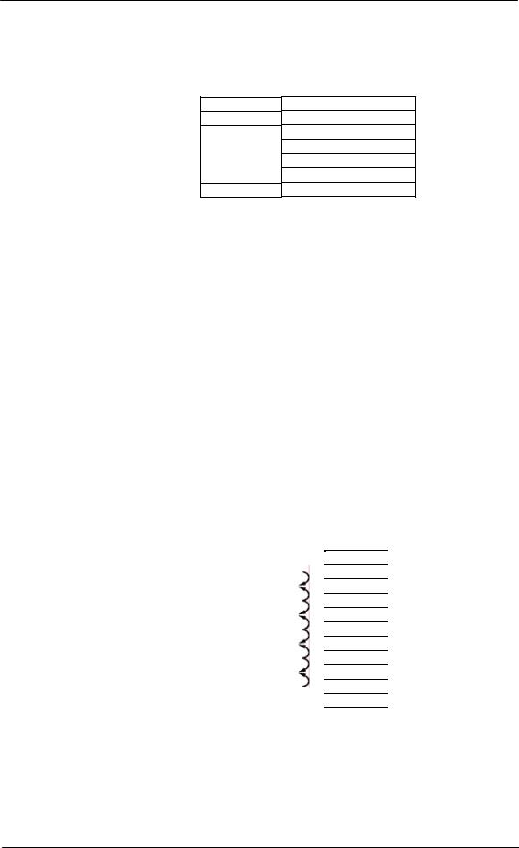
The following shows the possible fuse loading scenario for the Single-Slot and Double-Slot Distribution Modules. 20A fuse positions can be used only with factory wiring. When using 20A fuses, adjacent fuse positions must be left open.
For the Single-Slot Distribution Module with 10 GMT fuses, Field installation is only rated for 10A fuses. No more than 80A may be carried through the 10 fuse positions, or 40A through each half section. 15A and lower rated fuses may be used in any combination and position, as long as they do not violate the previous 80A/40A rule.
For the Single-Slot Distribution Module with 5 GMT fuses, a maximum load of 32 A is permitted with restrictions on the fuse positions. Specifically:
Position F1 defined as the bottom fuse position and F5 as the top fuse position.
1.Configuration #1 - F1+F2 <= 15A, F3<=15A, and F5+F4<= 10A
2.Configuration #2 - F1<=15A; F2=No Fuse; F3<=15A; F4=No Fuse; F5<=10A 3.
For the Double-Slot Distribution Module, each 8-fuse board can support a maximum of 80A.
|
|
|
|
|
|
|
Double-Slot |
||
|
Single-Slot Distribution Module |
|
|
Distribution Module |
|||||
Position |
Max Fuse |
|
Position |
|
Max Fuse |
|
Position |
Max Fuse |
|
10 |
|
|
10 |
|
15A |
|
8 |
|
15A/20A |
9 |
20A |
|
9 |
|
|
|
7 |
|
|
8 |
|
|
8 |
|
15A |
|
6 |
|
15A/20A |
7 |
20A |
|
7 |
|
|
|
5 |
|
|
6 |
|
|
6 |
|
15A |
|
4 |
|
15A/20A |
5 |
|
|
5 |
|
|
|
3 |
|
|
4 |
20A |
|
4 |
|
15A |
|
2 |
|
15A/20A |
3 |
|
|
3 |
|
|
|
1 |
|
|
2 |
20A |
|
2 |
|
15A |
|
|
|
|
1 |
|
|
1 |
|
15A |
|
|
|
|
(Arrows indicate alternate positions)
Issue 21 January 2008 |
28 |

CPS6000 –48V Indoor/Outdoor Power Shelf
Controller
There are two controller options for the CPS6000. The QS840A system controller allows for control and monitoring of system functions and setting of all system parameters. The QS841 provides integrated Ethernet access and other enhanced features. Refer to Section 5 for more controller details and Appendix A for programming information. The QS845A supplemental kit allows up to 3 supplemental shelves to be controlled by the QS840A/QS841A controller on the primary shelf.
Rectifiers
The constant-power rectifiers each occupy a single slot in the CPS6000 shelf. If a full complement of rectifiers is not required, a rectifier slot filler may be to cover empty rectifier slots. The slot filler is not necessary from an earthquake standpoint.
Model |
Amperage |
Comcode |
QS861A Rectifier |
15A low and high line ac |
108993531 |
|
|
|
QS852A Rectifier |
20A high line ac |
CC109106440 |
|
|
|
QS853A Rectifier |
25A high line ac |
CC109121290 |
|
|
|
QS862A Rectifier |
25A low line/30A high line ac |
108986704 |
|
|
|
QS864A Rectifier |
40A high line ac |
108994513 |
|
|
|
QS865A Rectifier |
50A high line ac |
108990074 |
|
|
|
QS850 Slot Filler |
N/A |
108994273 |
|
|
|
Ringer Chassis
Ringer Chassis each occupy a single Power Slot in the CPS6000 Shelf.
Ringer Chassis |
Comcode |
QS820M Ringer Chassis |
108991262 |
Ringer Output Cable
Ringer Cables one per Ringer Output (Ringer Chassis).
Item |
Comcode |
Ringer Output Cable H569-470 G kit – 15’ cable |
847922101 |
with connector for CPS6000/CPS2000 shelf on |
|
one end and unterminated leads on the other |
|
end. |
|
Ringer Output Cable – 150 ft |
CC848804765 |
Commercial - Molex: |
Commercial |
Plug 39-01-4031 |
|
Socket (3 per plug): |
|
Terminal Type 5556 |
|
16 AWG 39-00-0079 |
|
18 AWG 39-00-0059 |
|
Tool 11-01-0197 |
|
Ringers
Up to two Ringers plug into a Ringer Chassis.
Issue 21 January 2008 |
29 |

CPS6000 –48V Indoor/Outdoor Power Shelf
One Ringer per Ringer Chassis is non-redundant (simplex).
Two Ringers per Ringer Chassis is 1 + 1 redundant (duplex).
Ringer |
Comcode |
QS820A Ringer |
108990082 |
AC Power Cables
An ac power cable must be ordered. A standard ac cable set will not fit in the CPS6000 shelf. Verify that the sum of the input currents for all the rectifiers served by an ac circuit breaker does not exceed 80% of the breaker’s rating.
Table 3-A: Rectifier AC Input Current Table
|
|
|
|
|
|
|
|
|
|
|
Minimum Circuit |
|
75°C Minimum |
|
Lineage |
Model |
|
Nominal |
|
Number of |
|
|
|
Breaker value |
|
Recommended |
|||
Power |
Number of |
|
Input |
|
Rectifiers |
|
Nominal AC |
recommended |
|
Wire Gauge |
||||
Rectifier (A) |
Rectifier |
|
Voltage |
|
per AC feed |
|
Current (A) |
(A)* |
|
(AWG)* |
||||
|
|
120 |
|
1 |
|
7.8 |
|
15 |
14 |
|
||||
|
|
120 |
|
2 |
|
15.6 |
|
20 |
12 |
|
||||
|
|
120 |
|
3 |
|
23.4 |
|
30 |
10 |
|
||||
|
|
120 |
|
4 |
|
31.2 |
|
40 |
8 |
|
||||
15A |
QS861A |
120 |
|
5 |
|
39.1 |
|
50 |
8 |
|
||||
208 |
|
1 |
|
4.4 |
|
15 |
14 |
|
||||||
|
|
|
|
|
|
|||||||||
|
|
208 |
|
2 |
|
8.8 |
|
15 |
14 |
|
||||
|
|
208 |
|
3 |
|
13.2 |
|
20 |
12 |
|
||||
|
|
208 |
|
4 |
|
17.6 |
|
25 |
10 |
|
||||
|
|
208 |
|
5 |
|
22.0 |
|
30 |
10 |
|
||||
|
|
208 |
|
1 |
|
6 |
|
15 |
14 |
|
||||
20A |
QS852A |
208 |
|
2 |
|
12 |
|
15 |
14 |
|
||||
208 |
|
3 |
|
18 |
|
25 |
10 |
|
||||||
|
|
208 |
|
4 |
|
24 |
|
30 |
10 |
|
||||
|
|
208 |
|
5 |
|
30 |
|
40 |
8 |
|
||||
|
|
208 |
|
1 |
|
7.4 |
|
15 |
14 |
|
||||
25A |
QS853A |
208 |
|
2 |
|
14.8 |
|
20 |
12 |
|
||||
208 |
|
3 |
|
22.2 |
|
30 |
10 |
|
||||||
|
|
208 |
|
4 |
|
29.6 |
|
40 |
8 |
|
||||
|
|
208 |
|
5 |
|
37.0 |
|
50 |
8 |
|
||||
|
|
120 |
|
1 |
|
13.0 |
|
20 |
12 |
|
||||
|
|
120 |
|
2 |
|
26.0 |
|
35 |
8 |
|
||||
25/30A |
QS862A |
120 |
|
3 |
|
39.1 |
|
50 |
8 |
|
||||
|
208 |
|
|
1 |
|
|
8.8 |
|
15 |
|
14 |
|
||
|
|
|
208 |
|
|
2 |
|
|
17.6 |
|
25 |
|
10 |
|
|
|
|
208 |
|
|
3 |
|
|
26.4 |
|
35 |
|
8 |
|
|
|
|
208 |
|
|
4 |
|
|
35.3 |
|
45 |
|
8 |
|
40A |
QS864A |
208 |
|
1 |
|
11.8 |
|
15 |
14 |
|
||||
208 |
|
2 |
|
23.5 |
|
30 |
10 |
|
||||||
|
|
208 |
|
3 |
|
35.3 |
|
45 |
8 |
|
||||
50A |
QS865A |
|
208 |
|
|
1 |
|
|
14.5 |
|
20 |
|
12 |
|
|
208 |
|
|
2 |
|
|
29.1 |
|
40 |
|
8 |
|
||
|
|
|
|
|
|
|
|
|
|
|||||
*Conduit and further temperature deratings may be required in some installations .Cross-check table with local code and regulation requirements
Issue 21 January 2008 |
30 |
Loading...