


E9000

imagination at work
GE Energy
Industrial Solutions
Evolution Series E9000
Motor Control Centers
Installation & Maintenance Guide
DEH-40472 Rev. 05

Evolution Series E9000 Installation & Maintenance Guide
Contents
Warnings, Cautions & Notes . . . . . . . . . . . . . . . . . . . . . . . . . . . . . . . . . . . . . . . . . . . . . . . . . . . . . . . . . 2
1. Introduction . . . . . . . . . . . . . . . . . . . . . . . . . . . . . . . . . . . . . . . . . . . . . . . . . . . . . . . . . . . . . . . . . 3
General Description – Vertical Section Enclosures. . . . . . . . . . . . . . . . . . . . . . . . . . . . . . . . . . . . . 3
General Description – Motor Control Center Buses . . . . . . . . . . . . . . . . . . . . . . . . . . . . . . . . . . . . 4
General Description – Motor Control Center Units. . . . . . . . . . . . . . . . . . . . . . . . . . . . . . . . . . . . . 4
2. Receiving, Handling & Storage . . . . . . . . . . . . . . . . . . . . . . . . . . . . . . . . . . . . . . . . . . . . . . . . . 5
Receiving . . . . . . . . . . . . . . . . . . . . . . . . . . . . . . . . . . . . . . . . . . . . . . . . . . . . . . . . . . . . . . . . . . . . . . . . . . . 5
Handling. . . . . . . . . . . . . . . . . . . . . . . . . . . . . . . . . . . . . . . . . . . . . . . . . . . . . . . . . . . . . . . . . . . . . . . . . . . . 5
Storage . . . . . . . . . . . . . . . . . . . . . . . . . . . . . . . . . . . . . . . . . . . . . . . . . . . . . . . . . . . . . . . . . . . . . . . . . . . . . 5
3. Installation . . . . . . . . . . . . . . . . . . . . . . . . . . . . . . . . . . . . . . . . . . . . . . . . . . . . . . . . . . . . . . . . . . 6
Installation of Bottom Entry Conduits . . . . . . . . . . . . . . . . . . . . . . . . . . . . . . . . . . . . . . . . . . . . . . . . 6
Preparation of Flooring . . . . . . . . . . . . . . . . . . . . . . . . . . . . . . . . . . . . . . . . . . . . . . . . . . . . . . . . . . . . . . 7
Positioning and Joining Sections . . . . . . . . . . . . . . . . . . . . . . . . . . . . . . . . . . . . . . . . . . . . . . . . . . . . . 7
Bus Splicing . . . . . . . . . . . . . . . . . . . . . . . . . . . . . . . . . . . . . . . . . . . . . . . . . . . . . . . . . . . . . . . . . . . . . . . . . 8
Bus Splice Kits. . . . . . . . . . . . . . . . . . . . . . . . . . . . . . . . . . . . . . . . . . . . . . . . . . . . . . . . . . . . . . . . . . . . . . . 9
NEC Work Space . . . . . . . . . . . . . . . . . . . . . . . . . . . . . . . . . . . . . . . . . . . . . . . . . . . . . . . . . . . . . . . . . . . . 9
Installation of Top Entry Conduits . . . . . . . . . . . . . . . . . . . . . . . . . . . . . . . . . . . . . . . . . . . . . . . . . . . . 9
Equipment Wiring . . . . . . . . . . . . . . . . . . . . . . . . . . . . . . . . . . . . . . . . . . . . . . . . . . . . . . . . . . . . . . . . . . 10
Main Incoming Power Cables . . . . . . . . . . . . . . . . . . . . . . . . . . . . . . . . . . . . . . . . . . . . . . . . . . . . . . . 10
Individual Unit Wiring . . . . . . . . . . . . . . . . . . . . . . . . . . . . . . . . . . . . . . . . . . . . . . . . . . . . . . . . . . . . . . 10
Wiring NEMA Type A Motor Control Centers . . . . . . . . . . . . . . . . . . . . . . . . . . . . . . . . . . . . . . . . . 11
Wiring NEMA Type B Motor Control Centers . . . . . . . . . . . . . . . . . . . . . . . . . . . . . . . . . . . . . . . . . 11
Wiring NEMA Type C Motor Control Centers . . . . . . . . . . . . . . . . . . . . . . . . . . . . . . . . . . . . . . . . . 11
Wiring Between Sections . . . . . . . . . . . . . . . . . . . . . . . . . . . . . . . . . . . . . . . . . . . . . . . . . . . . . . . . . . . 12
Terminal Blocks . . . . . . . . . . . . . . . . . . . . . . . . . . . . . . . . . . . . . . . . . . . . . . . . . . . . . . . . . . . . . . . . . . . . 12
Installation of Motor Control Center Units . . . . . . . . . . . . . . . . . . . . . . . . . . . . . . . . . . . . . . . . . . . 12
Removal of Draw-out Motor Control Center Units. . . . . . . . . . . . . . . . . . . . . . . . . . . . . . . . . . . . 14
Operating Handles, Door Interlocks and Padlocking Provisions . . . . . . . . . . . . . . . . . . . . . . . 14
Operating Handle . . . . . . . . . . . . . . . . . . . . . . . . . . . . . . . . . . . . . . . . . . . . . . . . . . . . . . . . . . . . . . . . . . 15
Pilot Bracket and Door . . . . . . . . . . . . . . . . . . . . . . . . . . . . . . . . . . . . . . . . . . . . . . . . . . . . . . . . . . . . . 16
NEMA 3R Outdoor Enclosure Installation . . . . . . . . . . . . . . . . . . . . . . . . . . . . . . . . . . . . . . . . . . . . 16
4. Operation . . . . . . . . . . . . . . . . . . . . . . . . . . . . . . . . . . . . . . . . . . . . . . . . . . . . . . . . . . . . . . . . . . 18
Preparing for Initial Operation . . . . . . . . . . . . . . . . . . . . . . . . . . . . . . . . . . . . . . . . . . . . . . . . . . . . . . 18
Initial Operation of the Motor Control Center . . . . . . . . . . . . . . . . . . . . . . . . . . . . . . . . . . . . . . . . 18
Door Closing Procedure . . . . . . . . . . . . . . . . . . . . . . . . . . . . . . . . . . . . . . . . . . . . . . . . . . . . . . . . . . . . 19
5. Maintenance. . . . . . . . . . . . . . . . . . . . . . . . . . . . . . . . . . . . . . . . . . . . . . . . . . . . . . . . . . . . . . . . 20
Equipment Maintenance . . . . . . . . . . . . . . . . . . . . . . . . . . . . . . . . . . . . . . . . . . . . . . . . . . . . . . . . . . . 20
Control Power Fusing. . . . . . . . . . . . . . . . . . . . . . . . . . . . . . . . . . . . . . . . . . . . . . . . . . . . . . . . . . . . . . . 20
Suggested Maintenance Tools . . . . . . . . . . . . . . . . . . . . . . . . . . . . . . . . . . . . . . . . . . . . . . . . . . . . . . 20
Replacing or Adding Breaker Accessories to Plug-in E or F Frame Circuit Breaker . . . . . 21
Replacing a Control Power Transformer Mounted Under Disconnect . . . . . . . . . . . . . . . . . 21
Replace a Compact Starter (1/2 X) . . . . . . . . . . . . . . . . . . . . . . . . . . . . . . . . . . . . . . . . . . . . . . . . . . 21
Suggested Lifts . . . . . . . . . . . . . . . . . . . . . . . . . . . . . . . . . . . . . . . . . . . . . . . . . . . . . . . . . . . . . . . . . . . . 21
Publications Available from GE. . . . . . . . . . . . . . . . . . . . . . . . . . . . . . . . . . . . . . . . . . . . . . . . . . . . . . 22
Renewal Parts . . . . . . . . . . . . . . . . . . . . . . . . . . . . . . . . . . . . . . . . . . . . . . . . . . . . . . . . . . . . . . . . . . . . . 22
Ordering Additional or Replacement Parts. . . . . . . . . . . . . . . . . . . . . . . . . . . . . . . . . . . . . . . . . . . 23
Other Information . . . . . . . . . . . . . . . . . . . . . . . . . . . . . . . . . . . . . . . . . . . . . . . . . . . . . . . . . . . . . . . . . . 23
6. Overload Heaters . . . . . . . . . . . . . . . . . . . . . . . . . . . . . . . . . . . . . . . . . . . . . . . . . . . . . . . . . . . 24
Heaters for Ther-Mag Circuit Breaker Controllers . . . . . . . . . . . . . . . . . . . . . . . . . . . . . . . . . . . . 24
Heaters for Mag-Break Controllers . . . . . . . . . . . . . . . . . . . . . . . . . . . . . . . . . . . . . . . . . . . . . . . . . . 25
Heaters for Fused Controllers. . . . . . . . . . . . . . . . . . . . . . . . . . . . . . . . . . . . . . . . . . . . . . . . . . . . . . . 30
Heaters for Size 6 and 7 Fused Controllers . . . . . . . . . . . . . . . . . . . . . . . . . . . . . . . . . . . . . . . . . . 33
Electronic Overload for Circuit Breaker and Fused Controllers . . . . . . . . . . . . . . . . . . . . . . . . 33
1
DEH–40472
Warnings, Cautions & Notes
As Used In This Publication
WARNINGS
Warning notices are used in this publication to emphasize that hazardous voltages, currents, or other conditions that could cause personal injury are present in this equipment or may be associated with its use.
Warning notices are also used for situations in which inattention or lack of equipment knowledge could
cause either personal injury or damage to equipment.
CAUTIONS
Caution notices are used for situations in
which equipment might be damaged if care
is not taken.
NOTES
Notes call attention to information that is
especially significant to understanding and
operating the equipment.
This document is based on information available at the time of its publication. While efforts have been made to ensure accuracy, the information contained herein
does not cover all details or variations in hardware and software, nor does it provide for every possible contingency in connection with installation, operation, and
maintenance. Features may be described herein that are not present in all hardware and software systems. GE Energy assumes no obligation of notice
to holders of this document with respect to changes subsequently made.
GE Energy makes no representation or warranty, expressed, implied, or statutory, with respect to, and assumes no responsibility for the accuracy, completeness,
sufficiency, or usefulness of the information contained herein. No warrantees of merchantability or fitness for purpose shall apply.
© Copyright 2010 General Electric Company
All Rights Reserved
2
Evolution Series E9000 Installation & Maintenance Guide
Chapter 1 – Introduction
This publication provides guidelines for installation and
maintenance of Evolution Motor Control Centers, as
shown in Figure 1. The information provided does not
cover all details or variations in this product offering,
nor does it address all possible contingencies to be
met in connection with installation, operation, or maintenance. Should further information be desired, contact
GE Field Service Administration:
Call GE–RESOLve
1-888-437-3765
Refer to the GE requisition number found on the front
of the equipment when calling for assistance.
Disconnect equipment from all electrical
services before performing any installation
or maintenance work.
For additional information, including safety considerations for personnel working on this product, see NEMA
Standard Publication No. ICS 2.3, Instructions on the
Handling, Installation, Operation, and Maintenance of
Motor Control Centers.
General Description –
Vertical Section Enclosures
Each Evolution MCC vertical section is assembled with
two full-side sheets having openings near the top and
bottom for lateral busing and wiring between sections.
Multiple sections are joined together at the factory in
three-section (maximum) shipping splits. Each shipping
split is provided with continuous floor sills and a lifting
angle. Floor sills and lifting angles are field removable.
Each shipping split includes a continuous non-removable
main horizontal bus. Main bus splice bars are provided
within each shipping split for field connecting main
busses. Refer to motor control center outline drawings
furnished by the General Electric Company for location of
shipping splits within each motor control center lineup.
Vertical sections are normally provided with a top (12"
high) horizontal wireway and a bottom (6" high) horizontal
wireway. Each vertical section is also provided with a
vertical (4" wide) wireway. Hinged doors are provided
over horizontal and vertical wireways. (These doors can
be removed by extracting the hinge pins inside the doors.)
To open the external doors, rotate the
latches 90° counter-clockwise until the
screwdriver slots are vertical.
Secure Open
Because of the great variety of motor controller
assemblies and components provided within industrial
motor control centers and to satisfy floor-space limitations
at installation sites, a large variety of vertical section
dimensions are provided, as follows:
• Section Height: 90”, 78”, 66” etc.
• Section Width: 20”, 24”, 30” etc.
• Section Depth: 13”, 20”, 22” or deeper
for large assemblies.
Refer to motor control center drawings
furnished by GE before performing any
field-installation work.
Figure 1. Evolution Series three-section lineup.
3

Evolution Series E9000 Installation & Maintenance Guide
General Description –
Motor Control Center Buses
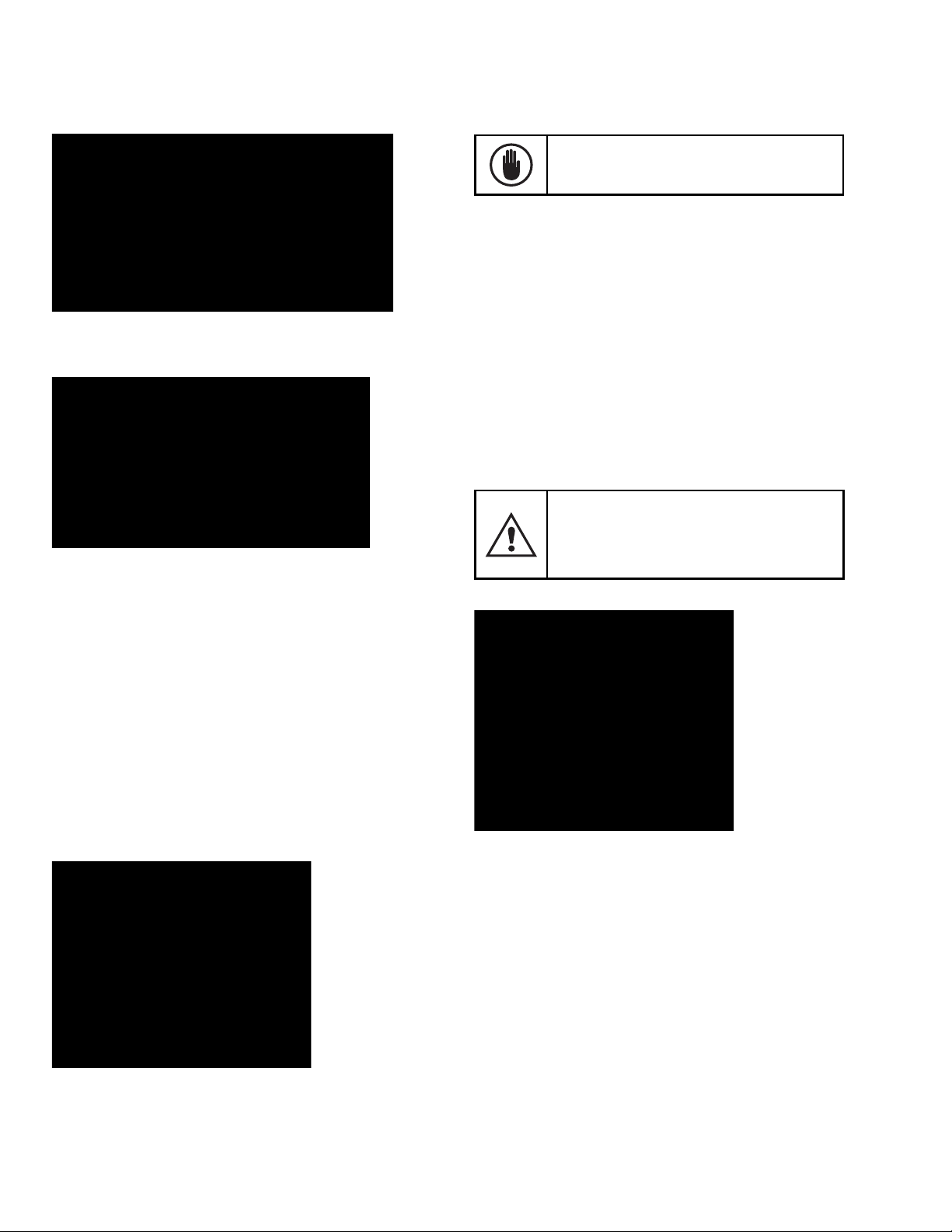
The main horizontal power bus is located at the top of
the vertical section. The bus bolted joints are accessible
from the front by loosening the barrier mounting screws
and sliding the Lexan
the main bus. Figure 2 shows a horizontal power bus
with its Lexan barrier. Figure 3 shows the bus barrier
mounting slots and screw.
The vertical bus, either 300A or 600/850 A, is connected
with two bolts per phase to the main bus. The phase
relationship is A–B–C from top to bottom and left to
right, as viewed from the front.
A continuous horizontal ground bus, sized in accordance
with the National Electrical Code, is provided near the
bottom of all motor control centers.
A optional vertical ground bus can be provided in each
section providing additional grounding. A neutral bus is
provided, when specified, in the bottom of the incoming
section or in the bottom of all enclosure(s) as specified.
®
bus barrier up and forward from
General Description –
Control Center Units
Consult Publication DET-291 for detailed listings of
Evolution MCC units.
Plug-in units are supplied with stabs rated at either
250 A or 600 A. Units above 600 A may be fixed (bolted) in place and are either bus or cable connected.
Installation and operation of units are described elsewhere in this guide.
Figure 2. Horizontal bus with Lexan barrier
Loosen screw,
lift and pull
barrier forward
Figure 3. Horizontal bus barrier mounting slot and screw
4

Evolution Series E9000 Installation & Maintenance Guide
Chapter 2 – Receiving, Handling & Storage
Receiving
Before leaving the factory, the motor control center is
given a final mechanical and electrical inspection and
is packed in accordance with the best practices for
electrical equipment.
On receipt of any apparatus, make an immediate
inspection for any damage or loss of equipment in
transit. Should damage or missing material be noted,
file a claim immediately with the carrier and notify the
nearest office of the General Electric Company.
Information such as a description of the damage, the
shipping crate numbers, the requisition numbers and
the panel catalog number should accompany the claim.
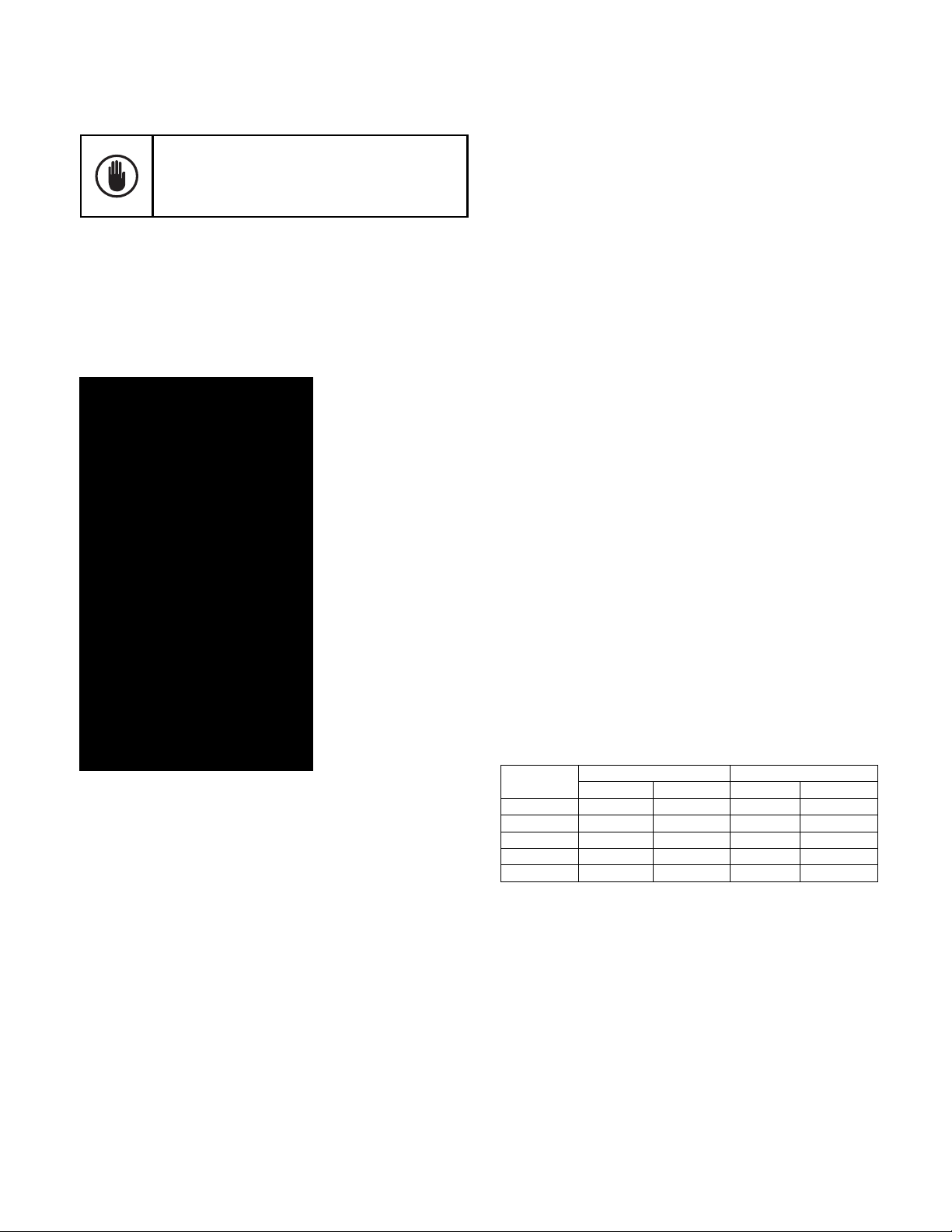
Handling
Control center sections are always shipped in an upright
position, in single or group sections. Sections must be
maintained in an upright position during all handling.
Never attempt to jack, lift, or move the equipment at
points other than the lifting angle or floor sills. Use two
or more chains or cables to distribute the weight evenly.
Pinch bars, pipe rollers or slings are useful implements
for handling equipment; but be careful to maintain
distributed loading and to always apply leverage at the
floor sills and/or lifting angle. Figures 4 and 5 illustrate
typical handling techniques.
Figure 5. Positioning the MCC with rollers
Storage
If it is necessary to store the equipment for any length
of time, be sure to observe the following precautions:
• Uncrate the equipment.
• Store the equipment in a clean, dry, humidity-controlled
area at moderate temperature. Cover with a suitable
canvas or heavy-duty plastic cover to prevent
entrance of foreign material.
• If equipment must be stored in cool or high humidity
areas, in addition to completely covering the equipment,
provide a heat source to prevent condensation of
moisture in the equipment . Energize space heaters (if
furnished in the equipment) or place a standard 120volt lamp rated at 75 watts inside the bottom of each
vertical section.
Figure 4. Using standard lifting angles to hoist the MCC
5

Evolution Series E9000 Installation & Maintenance Guide
Chapter 3 – Installation
Before any installation work is begun, consult all
drawings furnished by the General Electric Company
as well as all applicable contract drawings for the
particular installation. Pay particular attention to the
location of units in the motor control center and their
relations to existing or planned conduits and busways.
Installation of Bottom Entry Conduits
Conduits can be stubbed in after the location of the
motor control center lineup has been established. Conduit
should be stubbed approximately 2 inches (51mm)
above the finished floor line. Figure 6 and Figure 7 show
the conduit entrance space available at the bottom of
standard sections. Exceptions to this available space rule
are indicated on drawings furnished by GE for specific
installations. Center the conduit beneath the section
vertical wireway to facilitate direct cable entry. Note:
Bottom rear entrance should only be used with full
rear accessibility.
Figure 6C. Bottom conduit entrance for standard 20-inch deep
section, low bus position, 6-inch bottom cover.
Figure 6A. Bottom conduit entrance details for standard 13-inch
deep section, low bus position.
Figure 6B. Bottom conduit entrance details for standard 13-inch
deep section, bus upper position.
Figure 6D. Bottom conduit entrance details for standard 20-inch
deep section, bus upper position.
Figure 7A. Low bus position of ground and neutral bus (minimum
available space for conduit entry) in 13-inch deep section, 6-inch cover.
Figure 7B. Standard position of ground and neutral bus with 12-inch
cover compartment at the bottom of MCC.
6
Evolution Series E9000 Installation & Maintenance Guide
The overall height of the equipment should be considered
with respect to headroom, top conduit entry space and
alignment with other equipment.
Surface under motor control center base must
be of non-combustible material unless bottom
covers are installed in each vertical section.
Figure 7C. Low bus position of ground and neutral bus (minimum
available space for conduit entry) in 13-inch deep section, 6-inch cover.
Figure 7D. Upper position of ground and neutral bus (maximum
space available for conduit entry), 6-inch bottom cover.
Preparation of Flooring
For most installations, the MCC floor sills can rest on the
finished floor. The foundation for the equipment should
be level and even. Although not normally required, the
purchaser may elect to install, level and grout the steel
members or MCC floor sills in the floor, as illustrated in
Figure 8 and Figure 9. If the floor sills are removed, lifting
and moving the shipping sections must be done carefully.
If anchor bolts are to be imbedded in the foundation,
they must be located according to the drawings furnished
by GE for the specific equipment. For 13-inch (330.2
mm) deep vertical sections, anchor bolts or some form
of external bracing is required. Anchor bolts should be
1/2-inch diameter of Grade 2 steel (minimum).
If there are vertical sections of varying depths
(such as 13, 20, or 22 inches) in a single lineup,
the fronts of the sections must be lined up for
proper alignment of the main bus bars.
Figure 9 illustrates this point.
Figure 8. Control center floor sills grouted to the floor before
installation to provide a level foundation
Note: Cannot be rolled (as in Figure 5) without floor sills
7
Figure 9. Installing steel floor members
Note the front alignment of the 13-inch-deep section
Positioning and Joining Sections
If groups of sections are to be joined together in a final
lineup, remove the end cover plates and the plug buttons,
from the sides of the sections to be joined. Figure 10
shows the side views, with the end cover plates
removed, for 20-inch-deep sections with 2-inch (50.8
mm) and 4-inch (101.6 mm) bus bars.
Carefully check and remove dirt, dust or bits of packing
material from the interior of all sections. Use a brush,
soft cloth or vacuum cleaner.
Evolution Series E9000 Installation & Maintenance Guide
Do not use compressed air to clean the equipment
if it contains moisture. Remove all hardware packages, drawings and other items shipped with the
equipment. Check all nuts, bolts, and electrical joints
for tightness.
All cables entering the bottoms of sections should be
pulled through conduits to a point where they will be
accessible after the equipment is in place. Sections can
be moved to their final position and properly leveled.
Figure 11. Horizontal bus with Lexan barrier
Figure 10. Side view of a 20-inch-deep section showing the cover
plates, plug bottoms and joining points
Bus Splicing
Main, neutral and ground bus splice bars (with all associated hardware) are furnished, as necessary, to join
sections together. They are located in the first section to
the right of the joint. See Figures 13, 14 and 15 for approximate dimensions for main, neutral, and ground bus.
Remove the top Lexan barrier, as shown in Figure 11 and
Figure 12, to access the main bus. Refer to instruction
drawings in splice kit. See Table 2.
Loosen screw,
lift and pull
barrier forward
Figure 12. Horizontal bus barrier mounting slot and screw
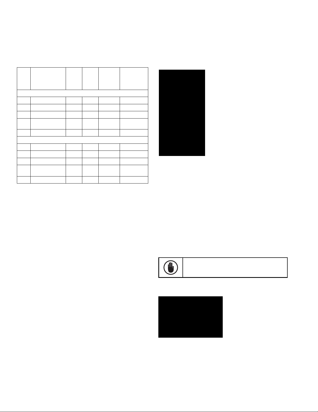
Table 1. Torque values for various bolt sizes and joint types.
Bolt Size
5/16-18 5–9 7–12 6.5–9 9–12
3/8-16 12–16 16–22 10–15 14–20
1/2-13 30–39 41–53 25–35 34–47
5/8-11 65–80 88–108 35–45 47–61
3/4-10 125–150 169–203 50–75 68–102
Note: When assembling or connecting to aluminum bus, apply a suitable joint
compound between the contacting surfaces.
Copper Joints Aluminum Joints
lb-ft N-m lb-ft N-m
8
Evolution Series E9000 Installation & Maintenance Guide
Bus Splice Kits
Table 2. Bus Splice Kits
Splicing From / To E9000/E9000
Main Bus Splice
Amps
Assembly Kit
Standard Splicing
600 110C1735G1SM 1 1/4 x 2 65K 110C1258TG1
800 110C1735G4SM 1 3/8 x 2 65K 110C1256TG1
1200 110C1735G7SM 1 1/2 x 2 100K 110C1253TG1
1600/
110C1735G12SM 2 1/2 x 2 100K 110C1263TG1
2000
2500 110C1735G13SM 2 1/2 x 2 100K 110C1785TG1
N3R and Spacer Shells
600 110C1735G14SM 1 1/4 x 2 65K 110C1258TG1
800 110C1735G15SM 1 3/8 x 2 65K 110C1256TG1
1200 110C1735G16SM 1 1/2 x 2 100K 110C1253TG1
1600/
110C1735G17SM 2 1/2 x 2 100K 110C1263TG1
2000
2500 110C1735G13SM 2 1/2 x 2 100K 110C1263TG1
*Included in kits.
Note: Standard plating is tin. Refer to factory for alternate plating.
Bars/
Phase
Copper
Size
(in.)
(thick x
width)
SC Rating
600V Max.
(sym.
amps)
Splice
Instruction
Drawing*
as illustrated. Note that for Condition 3, where there is
an enclosure on opposite sides of the working space,
the clearance for only one working space is required.
Figure 14. General Working Clearance Requirements
Installation of Top Entry Conduits
NEC Work Space
NEC Work Space is defined in Table 110.26(a) Working
Spaces. Included in these clearance requirements is the
step-back distance from the face of the equipment.
Table 110.26(a) provides requirements for clearances
away from the equipment, based on the circuit voltage
to ground, and whether there are grounded or ungrounded objects in the step-back space, or if there are exposed
live parts across from each other. The voltages to ground
consist of two groups: 0 to 150 and 151 to 600, inclusive.
Remember, where an ungrounded system is utilized, the
voltage to ground will be the greatest voltage between
the given conductor and any other conductor of the
circuit. For example, the voltage to ground for a 480volt ungrounded delta system is 480 volts.
See Figure 14 for general working clearance requirements.
Distances are measured from the live parts if the live
parts are exposed, or from the enclosure front if live
parts are enclosed. If any assemblies, such as switchboards or motor control centers, are accessible from the
back and expose live parts, the working clearance
dimensions would be required at the rear of the equipment,
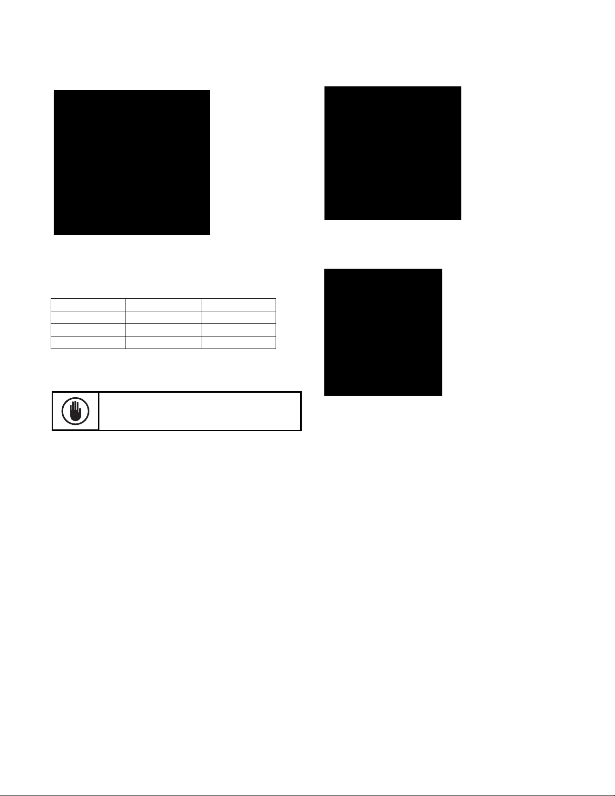
After the motor control center is in place and leveled, and
the sections are joined together, conduits can be brought
into the tops of sections as required. Figure 15 and
Figure 16 show the conduit entry space available at the
tops of standard sections. Refer to drawings furnished by
GE for deviations on specific installations. Note: Top rear
entrance should only be used with full rear accessibility.
Always remove top cover plates when drilling
holes. This prevents small metal chips from falling
into the panel and cause serious damage.
Figure 15. Top conduit entry space for 13-inch sections
9
Evolution Series E9000 Installation & Maintenance Guide
Figure 17. Typical top entry of main cables to the incoming-line lug
Figure 16. Top conduit entry space for 20-inch and 22-inch sections
Table 3. Dimensions for Figures 15 and 16
Width Dimension A Dimension B
20" 20" 17.56"
24" 24" 21.56"
30" 30" 27.56"
compartment (600A shown)
Equipment Wiring
When pulling, bending, and terminating field wiring,
avoid scraping, cutting or otherwise damaging
cable insulation or strands.
Main Incoming Power Cables
Refer to the motor control center drawings provided by
GE for the location of the main disconnect or incoming
line terminals and the direction (top or bottom) of cable
entry. Cable-bending room provided within the vertical
section will meet or exceed National Electrical Code
requirements.
Incoming line sections are provided with cable supports.
Incoming cables must be firmly secured to withstand
the significant forces that may be generated during a
short circuit .
Cables secured at each support, as illustrated in Figure
17 and Figure 18 (600A example), will adequately
brace cables for faults of 100K RMS symmetrical
amperes, based on horizontal bus bracing. However,
cables should always be secured at the first support
inside the enclosure and at the support nearest to the
incoming terminals. Insulated bushings are also recommended at conduit terminations.
Figure 18. Typical bottom entry or main cables to the incomingline lug compartment (600A shown)
Align the conduit linearly directly over or as close as
possible to the supports. Run the cable in a convenient
orientation, making sure the cable is located against
the supports before it connects to the cable terminals.
Lash the cable using the following procedure:
Wrap the line cables together and, if provided, tie cables
together with nominal 3/8-inch (9.5 mm) nylon rope or
rope having a minimum tensile strength of 2000 pounds
(8896 N), at 6 inches (152 mm) and 12 inches (305 mm)
from the line terminals. Use five wraps and complete
every additional 6 inches with five wraps or every 1 inch
(25 mm) with one wrap. Use supplied cable supports as
desired. Refer to UL 891.
Individual Unit Wiring
Open the vertical wireway door(s) and the top and/or
bottom horizontal wireway hinged covers. All doors
can be removed, if desired, by extracting hinge pins or
removing the hinge.
10
 Loading...