


 Loading...
CPS6000-M2
Frame-Mounted Battery Plant
Model H5694720
Product Manual
Select Code 167-793-112
Comcode CC848802595
Issue 8
January 2008
Notice:
The information, specifications, and procedures in this manual are subject to change without notice. Lineage Power assumes no responsibility for any errors that may appear in this document.
© 2008 Lineage Power
All International Rights Reserved
Printed in U.S.A.

CPS6000-M2 Installation Guide |
H5694720 |
Table of Contents |
|
1 Introduction.................................................................................................................... |
5 |
Document Objectives...................................................................................................... |
5 |
Additional Product Documentation ................................................................................ |
5 |
Customer Service Contacts............................................................................................. |
6 |
2 Product Description....................................................................................................... |
7 |
Architecture..................................................................................................................... |
8 |
Millennium II Controller................................................................................................. |
9 |
Rectifier Shelves ........................................................................................................... |
10 |
QS-Series Rectifiers...................................................................................................... |
12 |
QS-Series Ringers......................................................................................................... |
12 |
AC Input........................................................................................................................ |
14 |
Battery Options and Monitoring Features..................................................................... |
14 |
DC Distribution and Battery Termination .................................................................... |
15 |
Specifications................................................................................................................ |
16 |
3 Safety............................................................................................................................. |
21 |
Safety Statements.......................................................................................................... |
21 |
Warning Statements and Safety Symbols..................................................................... |
23 |
Precautions.................................................................................................................... |
24 |
Handling Batteries ........................................................................................................ |
25 |
Special Installation Notes ............................................................................................. |
26 |
4 Installation.................................................................................................................... |
28 |
Preparation .................................................................................................................... |
28 |
Anchoring Frame .......................................................................................................... |
31 |
Connecting Frame Ground............................................................................................ |
32 |
Connecting Central Office Ground (COG)................................................................... |
33 |
Connecting AC Utility .................................................................................................. |
34 |
Installing Batteries ........................................................................................................ |
35 |
Installing and Wiring DC Loads................................................................................... |
40 |
Installing QS-Series Rectifiers...................................................................................... |
44 |
Installing QS-Series Ringers......................................................................................... |
46 |
Controller Connections ................................................................................................. |
48 |
Installing Optional Circuit Packs.................................................................................. |
55 |
5 Controller User Interface............................................................................................ |
63 |
Controller Display Menu Maps .................................................................................... |
70 |
Minimum Controller Configuration.............................................................................. |
74 |
Controller Defaults........................................................................................................ |
79 |
Web Interface................................................................................................................ |
84 |
6 Acceptance Testing ...................................................................................................... |
89 |
7 Troubleshooting ........................................................................................................... |
92 |
Troubleshooting Controller Circuit Pack...................................................................... |
99 |
Modem and Data Switch Cards .................................................................................... |
99 |
Controller Alarm Descriptions.................................................................................... |
100 |
Clear Events................................................................................................................ |
104 |
Issue 8 January 2008 |
3 |

CPS6000-M2 Installation Guide |
H5694720 |
Uninstall Devices........................................................................................................ |
105 |
Troubleshooting QS-Series Rectifiers ........................................................................ |
105 |
Troubleshooting QS-Series Ringers ........................................................................... |
107 |
Troubleshooting VT-Probes........................................................................................ |
109 |
8 Ordering Information and Spare Parts .................................................................. |
110 |
9 Product Warranty...................................................................................................... |
118 |
Appendix A: Battery Functions................................................................................... |
120 |
Appendix B: EasyView for Windows® ........................................................................ |
127 |
Appendix C: Upgrading Software Through Network Connection Or Craft Port.. 130 |
|
Revision History............................................................................................................ |
134 |
Issue 8 January 2008 |
4 |

CPS6000-M2 Installation Guide |
H5694720 |
1 Introduction
Document Objectives
This manual provides installation and maintenance information for the Lineage Power CPS6000-M2 power system:
•Product Description
•Safety Information
•Installation Procedures
•Test and Acceptance
•Troubleshooting
•Controller and Rectifier Operations
•Product Warranty
Audience
Equipment Installers – Instructions for installation, test, and acceptance.
Equipment Users – Plant basics and troubleshooting.
CAUTION: This unit must be installed, serviced, and operated only by skilled and qualified personnel who have the necessary knowledge and practical experience with electrical equipment and who understand the hazards that can arise when working on this type of equipment.
Applications
The 48V CPS6000-M2 is ideally suited for small central office (CO) applications and high end huts and vaults.
Additional Product Documentation
For additional specification, engineering and installation information, refer to the following drawings as needed. These drawings may be accessed on our web site at http://lineagepower.com/. Click on Energy Systems Products/CPS6000 Plants.
|
Drawing |
Description |
|
|
|
H5694720 |
Ordering Guide |
|
|
|
167-790-063 |
Remote Peripheral Monitoring (RPM) |
|
|
|
157-010-202 |
210E Thermal Probe Multiplexer Module |
|
|
|
167-792-182 |
Advanced Features User Guide For The |
|
|
|
|
Millennium II |
|
|
|
|
|
|
|
Issue 8 January 2008 |
5 |
|||

CPS6000-M2 Installation Guide |
H5694720 |
Customer Service Contacts
Customer Service, Technical Support, Product Repair and Return, and Warranty Service
For customers in the United States, Canada, Puerto Rico, and the US Virgin Islands, call 1-800- THE-1PWR (1-800-843-1797). This number is staffed from 7:00 am to 5:00 pm Central Time (zone 6), Monday through Friday, on normal business days. At other times this number is still available, for emergencies only. Services provided through this contact include initiating the spare parts procurement process, ordering documents, product warranty administration, and providing other product and service information.
For other customers worldwide the 800 number may be accessed after first dialing the AT&T Direct country code for the country where the call is originating, or you may contact your local field support center or your sales representative to discuss your specific needs.
Customer Training
Lineage Power offers customer training on many Power Systems products. For information call 1-972-284-2163. This number is answered from 8:00 a.m. until 4:30 p.m., Central Time Zone (Zone 6), Monday through Friday.
Downloads and Software
To download the latest product information, product software and software upgrades, visit our web site at http://lineagepower.com/
Issue 8 January 2008 |
6 |

CPS6000-M2 Installation Guide |
H5694720 |
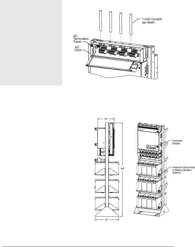
2 Product Description
The 48V CPS6000-M2 Power Plant is a 23 inch wide, front access, frame mounted battery plant. The system integrates QS series vertical airflow rectifiers and ringers, dc distribution options, battery connections and the Galaxy Millennium II controller in 500A and 1000A capacity systems. System dimensions are 25.5 inches wide, 15 inches deep and 29.8 inches tall (500A system) or 38.5 inches tall (1000A system). This allows the system to be mounted in either a 42 inch (1/2 height) frame for mounting on a battery stand or Unigy battery stack or in a 7 foot (full height) framework with battery trays.
The system operates directly from commercial power in 208/220/240Vac single phase @ 50/60Hz. 110Vac operation is also available with some rectifiers. AC connects to a terminal block panel at the top of the system.
48V CPS6000-M2 DC Power System Configuration
Issue 8 January 2008 |
7 |

CPS6000-M2 Installation Guide |
H5694720 |
Architecture
The plant architecture is shown in the diagram below. The CPS6000-M2 System rectifiers accept alternating current (ac) power and produce a regulated dc -48V nominal voltage distributed to float the batteries, power the controller and power the loads through distribution circuit breakers or fuses. Batteries are used to provide backup dc power when the ac is lost. They are connected in parallel with the rectifiers through either optional battery breakers or a low voltage disconnect (LVD). AC power is distributed to each rectifier through ac terminal blocks located in the ac termination panel at the top of the frame. The Millennium II system controller monitors and controls system operation.
CPS6000-M2 Block Diagram
Issue 8 January 2008 |
8 |
CPS6000-M2 Installation Guide |
H5694720 |
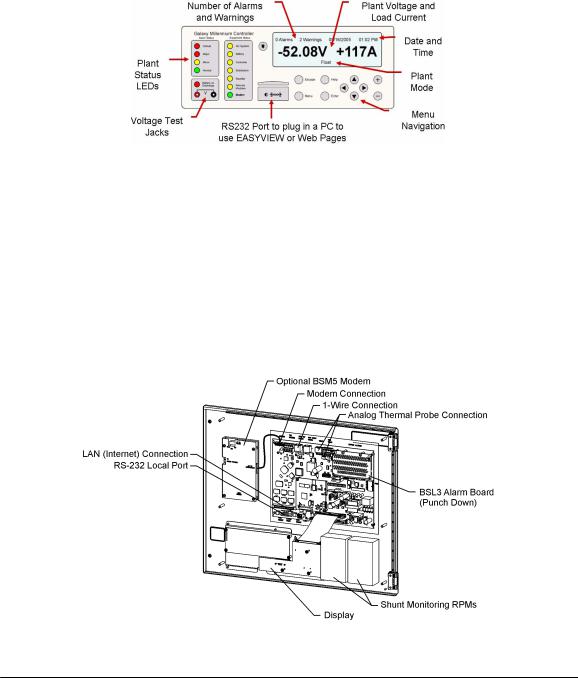
Millennium II Controller
The Millennium II controller is located on the door of the dc distribution. It uses an RS485 bus to serially monitor and control rectifiers, ringers and peripheral modules called RPM’s. It can also monitor and control external power equipment, including standby generators, converter plants, and inverters.
Local viewing and setting of system parameters and various alarm thresholds, user-definable alarm inputs and relays can be accessed either by a LCD graphics display with intuitive navigation mounted on the front door of the system or by the local RS-232 port connected to a notebook computer.
Remote access is available through a 10/100 Base-T network connection to the world wide web (internet) or your enterprise network (intranet) using standard browsers such as Microsoft Internet Explorer® or Netscape® Navigator. There is also an optional BSM5 56k bps modem available.
The controller performs various battery management functions to ensure peak performance and protection from thermal issues. In addition to monitoring for open battery breakers, measuring current from the battery shunt and monitoring and control of a optional low voltage battery disconnect contactor, the controller also measures battery string temperature and voltage with either traditional analog thermistor based temperature probes or digital QS873 Voltage/Thermal Probes (VT Probes) for slope thermal compensation. The VT probes connect in a daisy-chain fashion with one probe mounted to the negative post of each mid-string battery using the serial 1- Wire® bus.
Issue 8 January 2008 |
9 |
CPS6000-M2 Installation Guide |
H5694720 |
Rectifier Shelves
Rectifier shelves are equipped in either two shelf (500A system) or four shelf (1000A system) arrangements. DC output from each rectifier is bused up the back to the distribution and protected by clear lexan covers. Individual AC feeds from terminal blocks in the ac box route down the ac duct to a connector on each shelf. Serial communication cables daisy-chain from QS845A interface boards on the left side of each shelf and up to the controller.
The system is designed to allow field upgrades from two shelf to four shelf systems. This can be safely accomplished on working systems because the new shelves are first installed and then bus and cable links added.
DC Bussing to Rectifier Shelves (Rear View)
Issue 8 January 2008 |
10 |
CPS6000-M2 Installation Guide |
H5694720 |
QS845A Rectifier Interface Board Access
Rectifier Communication Connections
Issue 8 January 2008 |
11 |
CPS6000-M2 Installation Guide |
H5694720 |
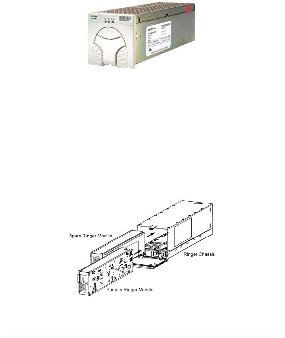
QS-Series Rectifiers
These constant power rectifiers are hot pluggable for quick installation. All interconnections (AC input, DC output, and control) are made automatically during insertion. The rectifiers communicate with the controller via a digital RS-485 serial cable allowing all rectifier settings to be made automatically by the controller. Load-share circuits allow all rectifiers to apportion the plant load equally, reducing the stress on individual units. The rectifier uses temperature dependent variable speed fans to provide vertical flow cooling. QS-series of rectifiers are available in 15A and 25A operating from 85VAC to 275VA and 20A, 30A, 40A, and 50A operating from 150VAC to 275VAC.
QS-Series Rectifier
QS-Series Ringers
QS820A Ringers convert -48Vdc to a 100VA ringing power output with configurable ac voltage, ac frequency, and dc offset. A ringer chassis may be installed in the two rightmost positions of any rectifier shelf. Each ringer chassis includes two vertical airflow fans, accepts up to two QS820A ringers, a primary and a spare, and provides a single ringing output. Install one ringer for non-redundant (simplex) operation and two ringers for redundant (duplex) operation. Should the primary ringer fail or be removed, the ringer output is provided by the spare ringer. The controller provides ringer output voltage and frequency settings, status and alarm communication. If communication is lost, the ringers continue to operate with the last received configuration.
QS820A Ringers and QS820M Chassis
Issue 8 January 2008 |
12 |

CPS6000-M2 Installation Guide |
H5694720 |
Types of Ringing
QS820 Ringers can be configured to provide one of three types of ringing: Battery Backed, Ground Backed, and Ground Backed-no dc. Ringing type is selected with jumper J12 on the chassis and by enabling or disabling dc Offset in the controller
Ground (VBUS+)
|
Ring Return |
|
Voltage |
tied to VBUS+ |
|
(Tip wire) |
||
|
-48Vdc (VBUS-)
Ring (Ring wire)
Battery Backed
(Common in USA)
Ring  (Ring wire)
Ground |
|
(VBUS+) |
|
Voltage |
|
-48Vdc |
|
(VBUS-) |
|
Ring Return |
|
tied to -48Vdc |
Ground Backed |
(Tip wire) |
Ground (VBUS+)
Voltage
-48Vdc (VBUS-)
Ring (Ring wire)
Ring Return tied to VBUS+ (Tip wire)
Ground Backed
No dc
Ring Signaling Types
Issue 8 January 2008 |
13 |
CPS6000-M2 Installation Guide |
H5694720 |
AC Input
•Connects to AC termination panel at the top of the system.
•One 1-inch conduit per shelf.
•Each rectifier fed individually by 10 gage wire protected with a 20A circuit breaker or fuse.
Battery Options and Monitoring Features
Battery Options
•Designed for operation with Flooded, VRLA, NiCad, and Lithium batteries (Nickel metal Hydride in the future).
•Half-height systems mount on Unigy II batteries, Full Height systems may be equipped with battery trays.
•Battery trays available for up to 170Ahr batteries with Anderson PowerPole® connectors or circuit breaker disconnects.
Battery Monitoring Features
•Open String (OS) Alarms
•Emergency Power Off (EPO) for disconnecting batteries from the system
•Temperature/voltage probes (up to 16) used in Battery Management options
Slope Thermal Compensation
Battery High Temp Disconnect
•Battery Discharge Test
•Battery Shunt
Low Voltage Battery Disconnect/Reconnect Contactor (LVBD)
Issue 8 January 2008 |
14 |

CPS6000-M2 Installation Guide |
H5694720 |
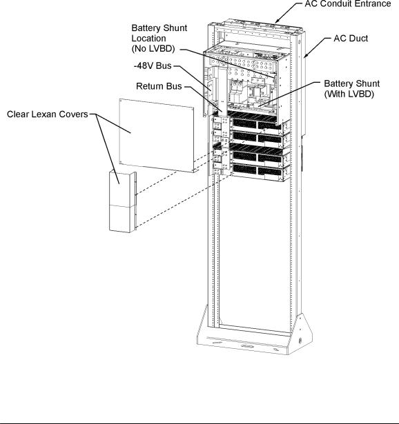
DC Distribution and Battery Termination
Group 660 Option
•Two 19 position bullet distribution panels each rated at 400A.
•12 pair of battery landings for battery cables up to 350Kcmil. (6 pair with 750Kcmil cable) 3/8” studs on 1” centers
•8 position center section for optional 800A Low Voltage Battery Disconnect (LVBD), GJ type circuit breakers with 25mV shunts or TPL-C fuse blocks with 1500A, 50mV shunts.
Group 661 Option
•One 19 position bullet distribution panel rated at 400A.
•One fuse panel rated at 600A equipped with 4 TPS fuses with 100A, 50mV shunt monitoring and 4 TPL-B fuses with 600A, 50mV shunt monitoring
•RPM shunt monitoring for fuse panel and up to 4 center TPL-C fuse blocks with 1500A, 50mV shunt monitoring
•12 pair of battery landings for battery cables up to 350Kcmil. (6 pair with 750Kcmil cable) 3/8” studs on 1” centers
•8 position center section for optional 800A Low Voltage Battery Disconnect (LVBD), GJ type circuit breakers with 25mV shunt or TPL-C fuse blocks with 1500A, 50mV shunt.
Issue 8 January 2008 |
15 |

CPS6000-M2 Installation Guide |
H5694720 |
Specifications
|
AC Input |
Input Distribution |
Terminal Blocks per rectifier fed from 20A breaker or fuse at the AC |
|
service panel. |
Wire Size |
10 AWG minimum for individual feeds. |
|
System Output |
System Voltage |
-48V |
Maximum Output Current: |
|
Two Rectifier Shelves (G255) |
450A charge, 500A discharge |
Four Rectifier Shelves (G256) |
800A charge, 1000A discharge |
Maximum Recharge Current |
Installed rectifier capacity minus plant -48V load |
Low-Voltage Disconnect |
39 to 50 Vdc |
Low-Voltage Reconnect |
39 to 55 Vdc |
|
|
Safety / Standards Compliance |
|
|
|
Safety Agency Approvals |
Underwriters Laboratories (UL) Listed per Subject Letter 1801: Power |
||||
|
|
Distribution Center for Communications Equipment, and cUL Certified |
|||
|
|
(CSA 22.2 950): Safety of Information Technology Equipment |
|
||
|
|
VDE licensed to VDE0805/EN60950 |
|
||
|
|
Rectifiers are individually UL Recognized (UL1950), cUL Certified |
|||
|
|
(CSA 22.2 234) or evaluated to EN60950 by an EC Notified Body, as |
|||
|
|
appropriate. |
|
||
European Economic Community |
EMC Directive 89/336/EEC, Low Voltage Directive 73/23/EEC as |
||||
(EEC) Directives |
amended by Marking Directive 93/68/EEC |
|
|||
Radiated and Conducted |
FCC Part 15, Class A |
||||
Emissions |
EN55022 (CISPR22), Class A |
|
|||
Harmonics |
EN61000-3-2 (IEC61000-3-2) |
|
|||
Voltage Fluctuations |
EN61000-3-3 (IEC61000-3-3) |
|
|||
Electromagnetic Immunity |
Meets Telcordia GR-1089-CORE |
|
|||
Electrostatic Discharge |
EN61000-4-2 Level 3 |
|
|||
RF Immunity |
IEC61000-4-3 Level 3, 10 V/m |
|
|||
EFT |
IEC61000-4-4 Level 3, No Error; Level 4, No Damage |
|
|||
Surge |
IEC 61000-4-5 Level 3, No Error; Level 4, No Damage |
|
|||
Conducted Immunity |
IEC 61000-4-6 Level 3, 10V |
|
|||
Voltage Dips, Interruptions, and |
IEC 61000-4-11 |
||||
Variations |
|
|
|
|
|
|
|
Environmental |
|
|
|
Operating Ambient Temperature |
-20 to 45 °C |
|
|||
Altitude |
-200 to 13,000 feet (-61 to 3962 meters) |
||||
|
|
See Note 1 |
|
||
Humidity |
10% to 95% non-condensing |
|
|||
Audible Noise |
< 60 dBA |
|
|||
Earthquake Rating |
Zone 2 or Zone 4, upper floors, depending on battery configuration |
|
|||
Note 1: For altitudes above 5000 feet, derate the temperature by 3.6 °F per 1000 feet. For altitudes above |
|||||
1524 meters, derate the temperature by 0.656 degrees Celsius per 100 meters. |
|||||
|
|
|
|
|
|
|
Issue 8 January 2008 |
16 |
|||

CPS6000-M2 Installation Guide |
H5694720 |
Installation Category
CPS6000-M2 is suitable for connection to ac utility systems where the expected level of lightning surges complies with ANSI C62.41 Category B or IEC 60664-1 Overvoltage Category II.
A service entrance surge protector is required in applications where the installation categories can not be classified as being compliant to either ANSI C62.41 Category B or IEC 60664-1 Overvoltage Category II.
CPS6000-M2 rectifiers have been tested for repeated lightning surges typically found in an Overvoltage Category III installation; however, a service entrance surge protector is recommended in cabinet applications to bring the power feeds in compliance to the installation categories above. The service entrance protection should be coordinated with the protection provided in the power modules.
The power module provides common-mode protection via a 320V MOV in series with a 2500V gas-discharge device and differential-mode protection via a 320V MOV in series with a 3.5A fuse
Issue 8 January 2008 |
17 |

CPS6000-M2 Installation Guide |
|
H5694720 |
|
Millennium II Controller |
|
||
|
|
|
|
General |
|
Specifications |
|
Input Voltage Range |
|
-48 Vdc (Range: 18-60V) |
|
Maximum Input Power |
|
36W depending upon options |
|
Display |
|
Graphic displayed arranged to |
|
|
|
8-line by 40-character backlit LCD |
|
Configuration Method |
|
Through front panel LCD display and menu keys |
|
|
|
Through IBM compatible PC with RS-232 port |
|
|
|
Through LAN internet connection |
|
Mounting Requirements |
|
Door mounted |
|
Input/Outputs |
|
Specifications |
|
Form C Alarm Output Contact Ratings |
|
60VDC at 0.5A |
|
Plant Voltage Measurement |
|
|
|
Accuracy |
|
48V Systems: ±40 mV |
|
0 to 50 °C (±.05% of full scale + 1 |
|
|
|
count) |
|
48V Systems: ±70 mV |
|
-40 to 85 °C (±0.1% of full scale + 1 |
|
0.01V |
|
count) |
|
|
|
Resolution |
|
|
|
Plant Current Measurement |
|
0 to +50 °C : ±0.5% of full scale |
|
Accuracy |
|
|
|
|
|
-40 to +85 °C: ±1.25% of full scale |
|
Resolution |
|
1A |
|
Temperature Measurement |
|
|
|
Accuracy |
|
-5 to +55 °C: ±2°C |
|
Thermistor temperature |
|
|
|
|
|
-40 to +85 °C: ±3°C |
|
One-Wire Serial probes |
|
-5 to +55 °C: ±1°C |
|
|
|
-40 to +85 °C: ±3°C |
|
Resolution |
|
0.1°C |
|
4-20mA Input Monitor |
|
|
|
Accuracy |
|
±100µA |
|
Resolution |
|
±10.0µA |
|
General (0-5V) Input |
|
0 to +50 °C: ±0.5% of full scale |
|
Accuracy |
|
|
|
|
|
-40 to +85 °C: ±1.0% of full scale |
|
Resolution |
|
0.01VDC |
|
Issue 8 January 2008 |
18 |

CPS6000-M2 Installation Guide |
|
H5694720 |
|
|
Rectifiers |
|
|
|
|
|
|
Item |
Specification |
|
|
Nominal Output Voltage |
48/52/54.5 Vdc |
|
|
Operating Output Voltage |
42 to 58 Vdc |
|
|
Ranges |
|
|
|
Boost Voltage |
48 to 58 Vdc |
|
|
Output Current |
QS861A: 0 to 15A at 54.5V |
QS852A: 0 to 20A at 54.5V |
|
|
QS862A: 0 to 30A at 54.5V |
QS853A: 0 to 25A at 54.5V |
|
|
|
QS864A: 0 to 40A at 54.5V |
|
|
|
QS865A: 0 to 50A at 54.5V |
|
Nominal Input Voltage |
QS861A: 100/120/208/240 |
QS852A: 208/240 Vac |
|
|
Vac |
QS853A: 208/240 Vac |
|
|
QS862A: 100/120/208/240 |
QS864A: 208/240 Vac |
|
|
Vac |
QS865A: 208/240 Vac |
|
Input Voltage Ranges |
QS861A: 85 to 275 Vac |
QS852A: 150 to 275 Vac |
|
|
(Shutdown from 135 to |
QS853A: 150 to 275 Vac |
|
|
150V) |
QS864A: 150 to 275 Vac |
|
|
QS862A: 85 to 275 Vac |
QS865A: 150 to 275 Vac |
|
|
(Shutdown from 135 to |
|
|
|
150V) |
|
|
Input Current |
QS861A: 8A at 120 Vac |
QS852A: 7.4A at 208 Vac |
|
|
4.4A at 208 Vac |
QS853A: 7.4A at 208 Vac |
|
|
QS862A: 13A at 120 Vac |
QS864A: 11.8A at 208 Vac |
|
|
8.8A at 208 Vac |
QS865A: 14.5A at 208 Vac |
|
Operating Frequency Range |
45 to 66 Hz |
|
|
Operating Temperature |
-40 to +65 °C |
|
|
Output Voltage Regulation |
±0.5% |
|
|
Output Noise, Ripple |
250 millivolts peak to peak maximum, over the range dc to |
|
|
|
100 MHz |
|
|
Load Share Accuracy |
1.5A maximum deviation between rectifiers |
|
|
Heat Dissipation at Full Load |
QS861A: 141W (480 BTU) per rectifier at 120 Vac operation |
|
|
|
160W (546 BTU) per rectifier at 240 Vac operation |
|
|
|
QS862A: 177W (604 BTU) at 100 to 120 Vac operation |
|
|
|
212W (724 BTU) at 200 to 240 Vac operation |
|
|
|
QS852A: 133W (454 BTU) per rectifier at 240 Vac operation |
|
|
|
QS853A: 151W (515 BTU) per rectifier at 240 Vac operation |
|
|
|
QS864A: 240W (819 BTU) per rectifier at 240 Vac operation |
|
|
|
QS865A: 267W (911 BTU) per rectifier at 240 Vac operation |
|
|
Selective High-Voltage |
Above 58 Vdc |
|
|
Shutdown |
|
|
|
Backup High-Voltage |
Above 60 Vdc for 1 millisecond |
|
|
Shutdown |
|
|
|
Issue 8 January 2008 |
19 |

CPS6000-M2 Installation Guide |
H5694720 |
Ringers
|
|
Item |
|
|
Specification |
||
Input Voltage |
-40 to -57 Vdc |
See Output VA Thermal Limiting. |
|||||
Nominal Input Voltage |
-48 Vdc |
|
|
||||
Input Current |
5 A max. |
|
|
||||
Output |
ac Component |
|
65 to 100 Vac |
|
|
||
Voltage |
|
|
|
Factory Default: 100Vac |
|||
|
|
ac tolerance |
± 5 Vac |
|
|
||
|
|
Regulation |
|
±5% ac component only |
|
||
|
|
dc Offset |
|
• |
-40 to +57 Vdc |
Battery Backed |
|
|
|
|
|
• |
+40 to +57 Vdc |
Ground Backed |
|
|
|
Type of ringing |
|
• |
0 Vdc |
Offset Disabled |
|
|
|
Battery Backed |
|
• |
dc Offset tracks dc Input Voltage |
||
|
|
|
• |
Factory Default: Enabled |
|||
|
|
Ground Backed |
|
||||
|
|
|
• |
Battery or Ground Backed is selected by Ringer |
|||
|
|
Ground Backed no-dc |
|
||||
|
|
|
|
|
Chassis jumper J12 or by external connection of Ring |
||
|
|
|
|
|
Rtn to Battery or to Ground. Factory Default: Battery |
||
|
|
|
|
|
Backed by Jumper |
|
|
|
|
dc Offset Tracking |
|
± 3 Vdc |
|
|
|
|
|
Error |
|
|
|
|
|
|
|
Harmonic Distortion |
5% THD |
|
|
||
|
|
Crest Factor |
|
1.21 to 1.51 |
|
|
|
Output Frequency |
|
15 to 50 Hz |
|
|
|||
|
|
|
|
Factory Default: 20 Hz |
|
||
|
Frequency tolerance |
± 1 Hz |
|
|
|||
|
|
|
|
|
|
|
|
Output |
|
|
|
100 VA |
|
|
|
VA |
|
|
|
|
|
|
|
|
|
Thermal Limiting |
|
Output VA may be reduced by reducing Vac when |
|||
|
|
|
|
operating simultaneously above 50°C and less than |
|||
|
|
|
|
-50Vdc input. |
|
|
|
|
|
|
|
Vac is reduced only sufficiently to prevent damage to the |
|||
|
|
|
|
ringer. |
|
|
|
Load Power Factor |
|
Operating: 0.5 Leading to 0.9 Lagging |
|||||
|
|
|
|
No Damage: 0 Leading to 0.7 Lagging |
|||
|
|
|
|
|
|
|
|
Operating Temperature |
-40 to +75 °C |
See Output VA Thermal Limiting. |
|||||
Heat Dissipation |
50 W (170 BTU / hr) |
|
|||||
Under Voltage Shutdown |
|
50% of Output Vac Set Point |
|||||
|
|
|
|
While shutdown due to external fault, restart will be |
|||
|
|
|
|
performed at approximately 2 minute intervals. |
|||
Issue 8 January 2008 |
20 |
CPS6000-M2 Installation Guide |
H5694720 |
3 Safety
Safety Statements
Please read and follow all safety instructions and warnings before installing, maintaining, or repairing the CPS6000-M2 System:
•The CE Mark demonstrates compliance with the European Union Council Directives for Low Voltage and EMC.
•The CPS6000-M2 platform is Underwriters Laboratories (UL) Listed per Subject Letter 1801, DC Power Distribution Centers for Telecommunications Equipment.
•CPS6000-M2 shelves equipped with QS820A ringers have hazardous secondary voltages on the secondary bus output connectors.
•Install only in restricted access areas (dedicated equipment rooms, equipment closets, or the like) in accordance with articles 110-16, 110-17, and 110-18 of the U.S. National Electric Code (NEC), ANSI/NFPA No. 70, and pursuant to applicable local codes.
•This equipment is to be used in controlled environments (an area where the humidity is maintained at levels that cannot cause condensation on the equipment, the contaminating dust is controlled, and the steady-state ambient temperature is within the range specified).
•This equipment has been evaluated for continuous use in ambient temperature from -40°C to 65°C.
•This equipment must not be installed over combustible surfaces.
•For installations in the United States, Listed compression connectors are to be used to terminate Listed field-wired conductors where required. For all installations, the appropriate connector is to be applied only to the correct size conductor as specified by the connector manufacturer, using only the connector manufacturer's recommended tooling or tooling approved for that connector.
•If the proper connector for the country of installation is not provided, obtain appropriate connectors and follow manufacturer’s and all local requirements for proper connections. All national and local rules and regulations should be followed when making field connections.
•The main output voltage (48V) meets SELV requirements.
•Insulation on field-wired conductors should be rated no less than 90° Celsius. Wire conductor size should be sized per electrical codes for 75° Celsius wire, and based on the ampacity of the associated protection device. Wiring internal to enclosed equipment cabinets should be rated at 105° Celsius (minimum).
Issue 8 January 2008 |
21 |

CPS6000-M2 Installation Guide |
H5694720 |
•Torque electrical connections to the values specified on labels or in the product documentation.
•Battery input cables must be dressed to avoid damage to the conductors (caused by routing around sharp edges or routing in areas where wires could get pinched) and undue stress on the connectors.
•Alarm contacts on the office alarm board are not fused; therefore, current limiting protection for these contacts must be provided by external circuits. Maximum ratings for alarm connections are 60Vdc and 0.5 amperes. Exceeding these maximum ratings could result in fire or damage to the unit.
•Fuse and/or circuit breaker loads must not exceed 80% of the fuse and/or circuit breaker current rating. Distribute loads across the panel.
•The short circuit current capability of the battery input to the distribution panel must not exceed 10,000A.
•AC branch circuits to this equipment must be protected with either fuses or circuit breakers sized as required by the National Electric Code (NEC) and/or local codes. The maximum size of the over-current protector is based on the type of shelf. Refer to the equipment ratings to assure rating of equipment will not exceed 80% of the value of the protector chosen.
•High leakage currents are possible due to contribution from simultaneous multiple AC input connections. Earth ground connection is essential before connecting the ac source to the shelf. This connection must be achieved by ensuring that the C.O. grounding stud is connected as shown in the Installation Section, or quality service personnel shall ensure that the rack system is bonded per the provision below.
•An accessible ac disconnect/protection device to remove power from the equipment in the event of an emergency must be provided. Disconnect all AC branch circuits prior to making AC connections.
•Installing fuses or circuit breakers not specified for use in these distribution modules may result in injury to service personnel or equipment damage. Use only replacement parts listed in this manual and on the equipment drawings.
•The telecom-type (e.g., GMT type) fuses can produce sparks during interruption or clearing of a fault on a high energy circuit. Use only fuses provided with safety caps for this type of circuit. Installing telecom-type fuses not equipped with safety caps may result in injury to service personnel.
•While installing batteries, follow all safety precautions outlined in the appropriate battery product manuals.
Issue 8 January 2008 |
22 |
CPS6000-M2 Installation Guide |
H5694720 |
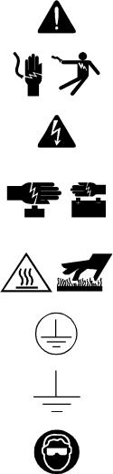
Warning Statements and Safety Symbols
The symbols may sometimes be accompanied by some type of statement; e.g., “Hazardous voltage/energy inside. Risk of injury. This unit must be accessed only by qualified personnel.” Signal words as described below may also be used to indicate the level of hazard.
|
|
Indicates the presence of a hazard that will cause death or severe personal |
|
|
|
DANGER |
injury if the hazard is not avoided. |
|
|
|
|
|
|
|
|
|
Indicates the presence of a hazard that can cause death or severe personal |
|
|
|
WARNING |
injury if the hazard is not avoided. |
|
|
|
|
|
|
|
|
|
Indicates the presence of a hazard that will or can cause minor personal |
|
|
|
CAUTION |
injury or property damage if the hazard is not avoided. |
|
|
|
|
|
|
|
|
|
This symbol identifies the need to refer to the equipment instructions for |
|
|
|
|
important information. |
|
|
|
|
|
|
|
|
|
These symbols (or equivalent) are used to identify the presence of |
|
|
|
|
hazardous ac mains voltage. |
|
|
|
|
|
|
|
|
|
This symbol is used to identify the presence of hazardous ac or dc |
|
|
|
|
voltages. It may also be used to warn of hazardous energy levels. |
|
|
|
|
|
|
|
|
|
One of these two symbols (or equivalent) may be used to identify the |
|
|
|
|
presence of rectifier and battery voltages. The symbol may sometimes be |
|
|
|
|
accompanied by some type of statement, for example: “Battery voltage |
|
|
|
|
present. Risk of injury due to high current. Avoid contacting conductors |
|
|
|
|
with non-insulated metal objects. Follow safety precautions.” |
|
|
|
|
One of these two symbols may be used to identify the presence of a hot |
|
|
|
|
surface. It may also be accompanied by a statement explaining the hazard. |
|
|
|
|
A symbol like this with a lightning bolt through the hand also means that |
|
|
|
|
the part is or could be at hazardous voltage levels. |
|
|
|
|
This symbol is used to identify the protective safety earth ground for the |
|
|
|
|
equipment. |
|
|
|
|
|
|
|
|
|
This symbol is used to identify other bonding points within the |
|
|
|
|
equipment. |
|
|
|
|
|
|
|
|
|
This symbol is used to identify the need for safety glasses and may |
|
|
|
|
sometimes be accompanied by some type of statement, for example: |
|
|
|
|
“Fuses can cause arcing and sparks. Risk of eye injury. Always wear |
|
|
|
|
safety glasses.” |
|
|
|
|
|
|
|
|
Issue 8 January 2008 |
23 |
||

CPS6000-M2 Installation Guide |
H5694720 |
Precautions
When working on or using this type of equipment, the following precautions should be noted:
•This unit must be installed, serviced, and operated only by skilled and qualified personnel who have the necessary knowledge and practical experience with electrical equipment and who understand the hazards that can arise when working on this type of equipment.
•The equipment could be powered by multiple ac inputs. Ensure that the appropriate circuit protection device for each ac input being serviced is disconnected before servicing the equipment. Do not disconnect permanent bonding provisions unless all ac inputs are disconnected.
•High leakage currents may be possible on this type of equipment. Make sure the equipment is properly safety earth grounded before connecting power.
•Batteries may be connected in parallel with the output of the rectifiers. Turning off the rectifiers will not necessarily remove power from the bus. Make sure the battery power is also disconnected and/or follow safety procedures while working on any equipment that contains hazardous energy/voltage.
•Hazardous energy and voltages are present in the unit and on the interface cables that can shock or cause serious injury. Follow all safety warnings and practices when servicing this equipment. When equipped with ringer modules, hazardous voltages will be present on the ringer output connectors.
In addition to proper job training and safety procedures, the following are some basic precautions that should always be used:
•Use only properly insulated tools.
•Remove all metallic objects (key chains, glasses, rings, watches, or other jewelry).
•Wear safety glasses. Fuses can produce sparks. High energy levels on buses and distribution components can produce severe arcing.
•Test circuits before touching.
•Lock out and tag circuit breakers/fuses when possible to prevent accidental turn on.
•Be aware of potential hazards before servicing equipment.
•Identify exposed hazardous electrical potentials on connectors, wiring, etc. (note the condition of these circuits, especially wiring).
•Use care when removing or replacing covers; avoid contacting circuits.
Issue 8 January 2008 |
24 |
CPS6000-M2 Installation Guide |
H5694720 |
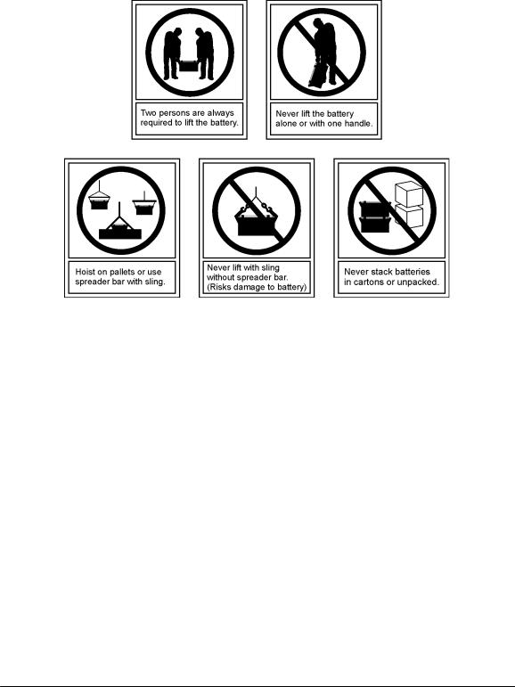
Handling Batteries
•To direct attention to the possible source of danger from battery gases, post one or more warning signs, lettered in large characters, in a conspicuous location near the battery. For example:
•Fully brief anyone who is permitted access to battery areas on the hazards of handling leadacid batteries. Make it clear to anyone handling, unpacking, or installing lead-acid batteries that they contain electrolyte (sulfuric acid and water). Everyone must wear protective equipment such as rubber gloves, rubber aprons, full face mask, and splash-proof goggles when performing any activity involving handling of batteries or cells containing electrolyte.
•A storage battery gives no indication by its appearance of the potential energy stored in it. All lead-acid storage cells/batteries have enormous short circuit capability which can result in serious burns. Use extreme care to avoid shorting out cell and/or battery terminals. Shorting a cell or battery with a non insulated tool can vaporize or throw the tool.
•All lead-acid batteries generate hydrogen gas, even under open circuit conditions. If not permitted to escape, this gas can build up to explosive concentrations. NEVER tamper with or block the vent caps of the 12IR125 battery modules. A damaged gas vent cap could become clogged, resulting in an explosion due to internal pressure. Such an explosion could short circuit other battery modules and result in a fire. ALWAYS place batteries in a wellventilated area. NEVER place battery modules in a sealed environment.
•In case of electrolyte contact with the skin, remove the electrolyte immediately by flushing the affected area with large amounts of plain tap water. In case of electrolyte in the eye, pour water into the inner corner of the eye and allow at least one quart of water to run over the eye and under the eyelid. Eye injuries should be treated by a physician immediately.
Issue 8 January 2008 |
25 |

CPS6000-M2 Installation Guide |
H5694720 |
Special Installation Notes
Deutsch
•Installationsanleitung
•Eingangsspannung ( Voltage ) : 120/200-240VAC , DC 54VDC Eingangsstrom ( Current ) : <15A per rectifier, DC 15A-1000A Eingangsleistung ( Watts ) :
Nennfrequenz ( Frequency ) : 50 / 60 Hz
•Seriennummer ( Assembly No. ): J5694720
•Modellnummer (Modell No. ) : H5694720
•Abmessungen sind nur zur Referenz : 978mm x 648mm x 381mm ( Dimensions are for reference only )
•Max. Umgebungstemperatur : max. 45 deg. C ( Max. Operation temperatur )
•Achtung: Für kontinuierlichen Feuerschutz sollte die Sicherung nur mit einer des gleichen Types ersetzt werden.
Sicherungswert :
( Warning : For continued protection against fire replace with same type and rating of fuse )
•Das System ist ein Gerät der Schutzklasse I / Überspannungs Kategorie II ( Power Supply is a Class I equipment / overvlotage category II )
•Ausgangsspannungen und -stöme: DC 58 V / SELV ( Output Voltage and Current )
• --Das Gerät darf nur in Räumen mit beschränktem Zutritt aufgestellt werden.
( Nur ausgebildetes Personal )
•--Nur für Aufstellung auf Boden oder einer anderen brennbaren Oberfläche geeignet.
•--Das Gerät hat keinen eigenen Ausschalter, es muß daher mit einem Einund Ausschalter im Versorgungskreis versehen sein.
•--Das Gerät ist für den Einbau in ITGeräte in einem Rahmen bestimmt (siehe weitere Anleitung)
•--Beim Einbau des Gerätes ist daraf zu achten das alle Anforderungen gemäß EN60950 eingehalten werden.
ACHTUNG: HOHER ABLEITSTROM
VOR ANSCHLUSS AN DEN VERSORGUNGSSTROMKREIS UNBEDINGT ERDUNGSVERBINDUNG HERSTELLEN
Issue 8 January 2008 |
26 |

CPS6000-M2 Installation Guide |
H5694720 |
Espanol
Notas especiales para instalaciones en países de habla hispana
•Instrucciones de instalación (Installation Instructions)
•Voltaje (Voltage): 120/200-240VAC
•Corriente (Current): <15A per rectifier Frecuencia (Frequency): 50/60Hz
•Voltaje y corriente de salida (Output Voltage and Current): 54VDC, 15A-1000A Temperatura máxima de operación (Maximum Operation Temperature):
45°C (113°F)
•Sin cabina contra incendios, suelo no combustible (No fire enclosure, non-combustible floor)
•Evaluado en EN60950 (Evaluated to EN60950)
Issue 8 January 2008 |
27 |

CPS6000-M2 Installation Guide |
H5694720 |
4 Installation
This section describes the following installation sequence for the CPS6000-M2 power system.
1.Preparations
2.Anchoring frame
3.Connecting frame ground
4.Connecting CO ground
5.Connecting ac utility
6.Installing batteries
7.Wiring dc loads and installing fuses/circuit breakers
8.Installing rectifiers and converters
9.Controller Connections
10.Starting Up System
Preparation
Safety
Please review all safety warnings in Section 3 before beginning the installation process. Observe all warnings and labels on the equipment.
WARNING: Due to the possibility of working on energized circuits during these procedures, all tools and test equipment must be insulated in an approved manner. Proper ESD protection is required in order to prevent ESD damage to the equipment.
WARNING: Only qualified personnel should install and service the power system and plug-in modules. Hazardous energy and voltages are present in the unit and on the interface cables and will shock or cause serious injury or death if safety precautions are ignored. Follow all safety warnings and practices when servicing this equipment.
Issue 8 January 2008 |
28 |

CPS6000-M2 Installation Guide |
H5694720 |
Wiring Guidelines
•All electrical connections should be made using the proper crimping tools and dies and should be torqued to values specified.
•All building wiring should comply with the NEC and other applicable local codes.
•The temperature rating of the wire must be 90°C minimum.. Wire gauge must be sized based on 75°C wire and the ampacity of the associated branch-circuit protection.
•Wiring internal to enclosed equipment cabinets must be rated no less than 105° Celsius.
Packaging
•All packages should be opened with a box cutter with the blade minimally exposed so that only the sealing tape is cut.
•Save all packaging material until the system has been powered up and all parts are operating within specifications.
Installation Tools
You will need the following tools to install and test the CPS6000-M2 System.
•Wire cutters and strippers
•Heat shrink gun
•5/16-inch (8 mm) hex driver
•Digital meter with an accuracy of ±0.02%
•Screw drivers (flat-blade and Phillips)
•ESD wrist strap
•48V test load
•Calibrated clamp-on dc current meter (0.1 ADC sensitivity)
•Torque wrench
•Socket wrenches:
−7/16” and 9/16” for load and battery connections;
−19 mm for anchor bolts;
−12" extension for socket
•Masonry drill kit as required
•Compression for installation of various compression lugs
•Protective canvas
•Insulating rubber mat
•Standard insulated installation tools, screwdrivers, etc.
•Windows-based personal computer laptop (PC) and cable to connect the PC communications port to the local port of the controller OR a CAT5 LAN cable.
Issue 8 January 2008 |
29 |

CPS6000-M2 Installation Guide |
H5694720 |
Accounting for Ship Loose Materials
QTY |
H5694720 Group |
COMCODE |
DESCRIPTION |
|
|
|
|
60 |
660, 661 |
802841635 |
Flat Washer, 3/8 |
|
|
|
|
60 |
660, 661 |
801829607 |
Lock Washer, 3/8 |
|
|
|
|
60 |
660, 661 |
841064777 |
Nut Hex, 3/8 |
|
|
|
|
40 |
660, 661 |
230707-1 |
Amp Barrel Terminal |
|
|
|
|
144 |
660, 661 |
901352617 |
Nut ¼ - 20 |
|
|
|
|
3 |
441, 451, 471 |
406954222 |
Cable ties for securing battery cables |
|
|
|
|
1 |
441, 451, 471 |
CC848809104 |
2 gauge battery cable |
|
|
|
|
2 |
440-471 |
901281444 |
Phillips flat head screws 10-32 x 3/8 |
|
|
|
|
3 |
440-471 |
848466884 |
Battery separators |
|
|
|
|
1 |
440, 441, 451, 471 |
CC848768201 |
Front battery bracket |
|
|
|
|
1 |
441, 451, 471 |
CC848770248 |
Clear cover for battery breaker |
|
|
|
|
2 |
441, 451, 471 |
845143858 |
Screw 6-32 x ¼ |
|
|
|
|
2 |
101-104 |
CC408575947 |
¼-20 x ¾-inch HH bolt |
|
|
|
|
2 |
101-104 |
801829557 |
¼-inch lockwasher |
|
|
|
|
2 |
101-104 |
CC408576012 |
¼-inch flat washer |
|
|
|
|
1 |
104 |
CC848795385 |
Drill template |
|
|
|
|
Torque Requirements
Torque (in-lb) |
Connection |
10 |
AC terminal block screws |
35 |
10-32 screw for dc rear covers and ac duct |
35 |
12-24 frame-mounting screws |
65 |
1/4-20 nuts for bullet panel loads |
135 |
M8 bolts for large breaker and fuse kits and LVBD connections |
240 |
3/8-16 nuts for large breaker and fuse load leads and all battery leads |
Issue 8 January 2008 |
30 |
Loading...