


ADVANCED SNMP WEB INTERFACE CARD
Table of contents
 Loading...
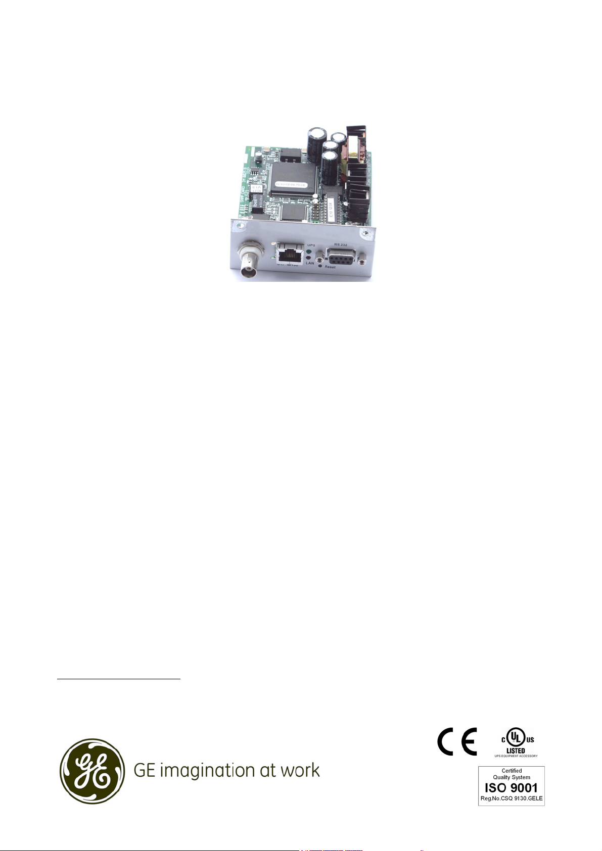
GE
Consumer & Industrial
Operating Manual
Digital Energy™
ADVANCED SNMP
WEB INTERFACE CARD
( for firmware version 1.84 or higher )
SG Series 10 - 500 / 400VAC CE / 480VAC UL
SitePro 10 - 500 kVA / 400VAC CE
SitePro A 10 - 300 kVA / 208-480VAC UL
LP 33 / 10, 20 & 30 kVA / 400VAC CE / Series 4
LP 33 / 10 & 20 kVA / 208VAC UL / S e ries 1
GE Consumer & Industrial SA
General Electric Company
CH – 6595 Riazzino (Locarno)
Switzerland
T +41 (0)91 / 850 51 51
F +41 (0)91 / 850 51 44
www.gedigitalenergy.com

Modifications reserved Page 2/33
OPM_CNT_ADV_SNM_CRD_XGB_V050.doc Operating Manual ADVANCED SNMP / WEB INTERFACE CARD
Model ADVANCED SNMP / WEB INTERFACE CARD
Date of issue: 01.02.2007
File name: OPM_CNT_ADV_SNM_CRD_XGB_V050
Author: Lorenzo Giuntini
Revision: 5.0
Identification No. 11701
Up-dating
Revision Concerns Date
3.1 General review for UL and new layout 15.06.2004
4.0 Without BNC, new layout and company name changes (GE) 06.12.2004
5.0 Introduction of PMAD functionality 12.12.2006
Table of contents Page
1 CONTENT OF THE KIT.........................................................................................................................................................................................3
2 INTRODUCTION .................................................................................................................................................................................................... 4
3 SPECIFICATION ..................................................................................................................................................................................................... 5
4 INSTALLATION.......................................................................................................................................................................................................6
5 REMOVE ...................................................................................................................................................................................................................9
6 CONFIGURATION METHODS........................................................................................................................................................................10
6.1 CONFIGURATION OVER THE NETWORK ............................................................................................................................................................. 10
6.2 CONFIGURATION VIA A SERIAL CONNECTION................................................................................................................................................. 10
7 CONFIGURATION OPTIONS .......................................................................................................................................................................... 11
8 USE..........................................................................................................................................................................................................................17
8.1 SNMP AGENT.................................................................................................................................................................................................................. 17
8.2 WEB SERVER................................................................................................................................................................................................................... 17
8.2.1 Login and UPS Identification web page.............................................................................................................................................................................. 17
8.2.2 UPS Details web page..................................................................................................................................................................................................................20
8.2.3 UPS Alarms web page ................................................................................................................................................................................................................. 21
8.2.4 UPS Tests web page ..................................................................................................................................................................................................................... 22
8.2.5 UPS Control web page................................................................................................................................................................................................................. 24
8.2.6 UPS Configuration web page ...................................................................................................................................................................................................25
8.2.7 Agent Configuration web page ............................................................................................................................................................................................... 26
8.2.8 Trap Configuration web page.................................................................................................................................................................................................. 27
8.2.9 Special Functions web page..................................................................................................................................................................................................... 28
9 UPDATE FIRMWARE.........................................................................................................................................................................................29
9.1 UPDATE FIRMWARE USING TELNET OR SERIAL LINE.................................................................................................................................... 29
9.2 UPDATE FIRMWARE USING WEB BROWSER..................................................................................................................................................... 30
10 SUPPORTED MIB VARIABLES .......................................................................................................................................................................31
11 SUPPORT ..............................................................................................................................................................................................................32
COPYRIGHT © 2007 by GE Consumer & Industrial
All rights reserved; reproduction without permission prohibited.
This manual may be subject to change; no liability can be accepted for any error or omission.

Modifications reserved Page 3/33
OPM_CNT_ADV_SNM_CRD_XGB_V050.doc Operating Manual ADVANCED SNMP WEB INTERFACE CARD
1 CONTENT OF THE KIT
The advanced SNMP Card is delivered with the following material:
User Manual
Special note for
SitePro installation
Advanced SNMP Card
IM0025
Square plates and
screws for older
SitePro UPS
Smaller front panel for
SitePro and SG Series UPS
Modifications reserved Page 4/33
OPM_CNT_ADV_SNM_CRD_XGB_V050.doc Operating Manual ADVANCED SNMP / WEB INTERFACE CARD
2 INTRODUCTION
WARNING !
The work to be done is reserved to Service engineers which have been previously
trained on these UPS's, and therefore have thorough knowledge about the
function and handling of this equipment.
Introduction
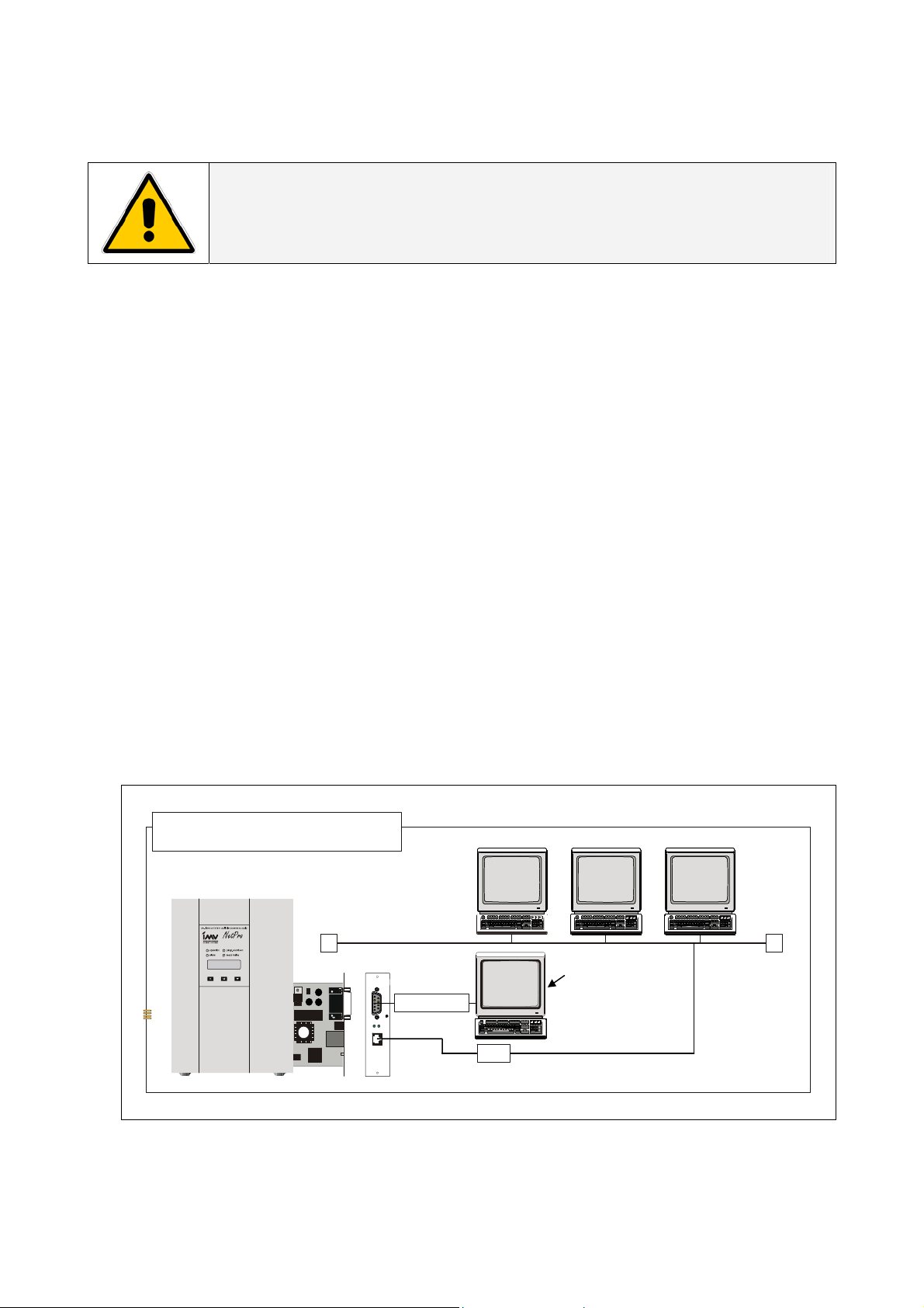
The SNMP/Web Interface is designed to present information about the UPS on the network.
The interface provides the UPS information in two ways:
• SNMP Agent
The SNMP information complies to the standard UPS-MIB which is defined in RFC1628.
Additional information are available with the GESingle and GEParallel MIB.
This format allows one or more NMSs (Network Management System) to monitor, manage and
control the UPS.
In addition, GE supports protection software and remote monitoring software using this information
to determine the status of the UPS and guarantee safe and orderly shutdown when necessary.
• Web Server
The UPS information is also available in HTML format. HTML is the basic language for internet
communication. Every standard internet browser can be used to monitor and control the UPS using
HTML from anywhere on the network or even from anywhere in the world when using the internet.
A
RCHITECTURE DIAGRAM
WIN
95
WIN
NT
UNI
X
Etherne
t
Comport PC
(conso le)
NOTE:
only required for
configuration
UTP
1:1 RS232
10/100 Mbits

Modifications reserved Page 5/33
OPM_CNT_ADV_SNM_CRD_XGB_V050.doc Operating Manual ADVANCED SNMP / WEB INTERFACE CARD
3 SPECIFICATION
Here follows a short description regarding the different plugs present on the frontal panel of the card:
RS232 Port
Used only to
configure the
parameters of the
card (9600-N-8-1).
(see cha
p
ter 6).
Reset Button
For a complete
reset of the card.
Red Led
Indicates the
transmission and
reception of the
packets over the
LAN bus.
RJ45 Connector
Used to
communicate with
10 or 100 Mbits
according to the
standard 10Base - T
or 100Base –TX.
Green Led
Indicate 4 different operating modes of the card:
1. When on and stable, it indicates that the card is
powered, but there is no communication with the UPS.
2. When blinking slow (1/sec.), it indicates that the card is
powered and there is communication with the UPS.
3. When blinking fast (6/sec.), it indicates the card is
updating the ROM and in this case, it is most important
not to reset or disconnect the card.
4. If the card is started in the restore mode, the led is
blinking corresponding to the SOS notification (...---...).

Modifications reserved Page 6/33
OPM_CNT_ADV_SNM_CRD_XGB_V050.doc Operating Manual ADVANCED SNMP / WEB INTERFACE CARD
4 INSTALLATION
WARNING !
The work to be done is reserved to Service engineers which have been
previously trained on these UPS's, and therefore have thorough knowledge
about the function and handling of this equipment.
1 Check if the card has the correct logical address.
The logical address is installed trough the jumper JP5, JP6 in the following way:
Logical Address [dec] Jumper 5 Jumper 6
SNMP Card 0
(1)
84 Installed Installed
SNMP Card 1 85 Installed Not installed
SNMP Card 2 86 Not installed Installed
SNMP Card 3 87 Not Installed Not Installed
(1) Default setup
IMPORTANT: Attention for correct direction of the jumpers.
NOTE: - The setting of the jumper can be disabled with a specific configuration parameter (see
chapter 6, parameters “O”)
- The logical address is only important when more than one SNMP Card is installed on the
same UPS system.
NOTE !
Please refer to the “Safety Rules” included in the “Operating Manual” of the UPS.
Please read carefully the UPS “Operating Manual & installation Guide” before
installing or operating the equipment.
If any problems are encountered with the description of this installation guide,
please contact the nearest Service Centre before proceeding.
Jumper 5
Jumper 6

Modifications reserved Page 7/33
OPM_CNT_ADV_SNM_CRD_XGB_V050.doc Operating Manual ADVANCED SNMP WEB INTERFACE CARD
2 Install the SNMP Card in option slot.
IMPORTANT: Switch off the UPS, and wait approx. 2 minutes or switch the UPS to the manual bypass.
Please ensure that the mains input is reliable during this period.
All cables must be disconnected from the card during the installation.
Install procedure for LANPRO 33 / LP 33 Series
Q
1
L
P
3
3
_
3
0
_
U
P
S
w
i
t
h
o
u
t
p
r
o
t
e
c
t
i
o
n
s
_
0
1
Q
2
F
1
F
3
F
2
1. Remove the plate that covers the Option slot by cutting the edges which are holding the plate.
Take care the plate does not fall inside the UPS!
2. Slide carefully the SNMP Card into the Options slot.
3. Fix the frontal plate of the SNMP Card to the UPS, using the screw included in the SNMP Interface
Card kit.
Install procedure for SitePro S6
Q2
Q1
Q4
1. Change the frontal plate with the smaller one delivered with the Kit.
2. Insert the SNMP Card in the options slot.
3. Fix the frontal plate of the SNMP Card to the connectivity box, using the screw included in the
SNMP Interface Card kit.
SNMP
CARD
Connectivity box
SP_150-200_S6_customer interface_01
XA
J11
P4
SNMP
PROTECTION
PLATE
Option slot (see
description below
for procedure)
Customer interface
Modifications reserved Page 8/33
OPM_CNT_ADV_SNM_CRD_XGB_V050.doc Operating Manual ADVANCED SNMP WEB INTERFACE CARD
Install procedure for SG Series
SGT5000_050-080_UPS_GE_03
Q1
OFF
ON
Q2
ON
OFF
1. Change the frontal plate with the smaller one delivered with the Kit.
2. Insert the SNMP Card in the options slot.
3. Fix the frontal plate of the SNMP Card to the connectivity box, using the screw included in the
SNMP Interface Card kit.
3 Make all necessary connections (see architecture diagram in chapter 2)
4 Check that after a while (max. 30 sec.) the green led starts to blink.
This means that the communication with the UPS is established.
5 Switch on the UPS or go back to normal mode from bypass.
Connectivity box
CNT_Customer Interface_01
P4
Adv. SNMP Card
Protection
Plate
Modifications reserved Page 9/33
OPM_CNT_ADV_SNM_CRD_XGB_V050.doc Operating Manual ADVANCED SNMP / WEB INTERFACE CARD
5 REMOVE
WARNING !
The work to be done is reserved to Service engineers which have been
previously trained on these UPS's, and therefore have thorough
knowledge about the function and handling of this equipment.
NOTE !
The installation and cabling of the option “Advanced SNMP/
WEB Interface” must be performed by QUALIFIED SERVICE
PERSON.
Please refer to the “Safety Rules” included in the “Operating Manual” of
the UPS.
Please read carefully the UPS “Operating Manual & installation Guide”
before installing or operating the equipment.
If any problems are encountered with the description of this installation
guide, please contact the nearest Service Centre before proceeding.
1 Switch off the UPS, and wait approx. 2 minutes or switch the UPS to the manual
bypass
Please ensure that the mains input is reliable during this period.
2 Remove all connections from the Advanced SNMP Card
3 Remove the Advanced SNMP Card from the slot
4 Switch on the UPS or go back to normal mode from bypass

Modifications reserved Page 10/33
OPM_CNT_ADV_SNM_CRD_XGB_V050.doc Operating Manual ADVANCED SNMP / WEB INTERFACE CARD
6 CONFIGURATION METHODS
Configuration of the SNMP Card can be done in two ways:
Via the network ( Chapter 6.1) or using a serial connected computer with a terminal emulation program (
Chapter 6.2).
For full configuration of the SNMP Card from the network, a BOOTP or DHCP Server must be available on
the network.
6.1 CONFIGURATION OVER THE NETWORK
The factory default way of retrieving an IP-address is by using DHCP.
On the card you will find a sticker with its MAC-address that needs to be configured in the BOOTP/DHCP
server.
After assigning the IP-address to this MAC-address in the BOOTP/DHCP Server the card needs to be
rebooted to retrieve this IP-address.
For a reboot press the reset button on the card.
NOTE
: the SNMP Card recognizes a BOOTP-reply from the server only when this latter uses broadcast
addressing for the destination on both the MAC and the IP address fields.
Configuration of the other parameters can be performed using either a telnet program or a Web-
browser.
The default loginname and password are both ‘GE’.
After having passed the login info the configuration screen will appear.
For security reasons we suggest to change the default loginname and password immediately!
Please proceed with Chapter 7 (Telnet) or Chapter 8.2 (Web Browser).
6.2 CONFIGURATION VIA A SERIAL CONNECTION
Connect the SNMP Card to the computer using a standard 1:1 serial cable.
Run a terminal simulator like Windows Terminal or Hyperterminal.
Configure your terminal simulator as follows:
9600 bps, 8 data bits, 1 stop bit, none parity check, none flow control.
Terminal emulation: VT-100
Establish a connection and press <x>.
The configuration screen will appear. Please proceed with Chapter 7.
Loading...