


GE Consumer & Industrial
Electrical Distribution
AF-60 LPTM Micro Drive
Operating Instructions

AF-60 LP™ Micro Drive Operating Instructions
Contents
1 Safety |
5 |
Safety Instructions |
5 |
Software Version and Approvals |
6 |
General Warning |
7 |
Avoid unintended Start |
7 |
Before Commencing Repair Work |
8 |
2 Mechanical Installation |
9 |
Before Starting |
9 |
Mechanical Dimensions |
10 |
3 Electrical Installation |
11 |
How to Connect |
11 |
Electrical Installation in General |
11 |
Fuses |
12 |
EMC-Correct Installation |
13 |
Mains Connection |
13 |
Motor Connection |
14 |
Control Terminals |
15 |
Connecting to Control Terminals |
16 |
Switches |
16 |
Power Circuit - Overview |
17 |
Load sharing/Brake |
18 |
4 Programming |
19 |
How to Programme |
19 |
Programming with DCT-10 Set-up Software |
19 |
Programming with the Keypad |
19 |
Status Menu |
21 |
Quick Menu |
21 |
Quick Menu Parameters |
22 |
Main Menu |
25 |
5 Modbus RTU |
27 |
Modbus RTU Overview |
27 |
Modbus RTU Message Framing Structure |
28 |
Remote Terminal Unit |
28 |
Modbus RTU Message Structure |
28 |
Start/Stop Field |
28 |
Address Field |
29 |
Function Field |
29 |
DET-579A |
1 |

AF-60 LP™ Micro Drive Operating Instructions |
|
Data Field |
29 |
CRC Check Field |
29 |
Coil/Register Addressing |
29 |
How to Control the frequency converter |
31 |
Function Codes Supported by Modbus RTU |
31 |
Exception and Error Codes |
31 |
How to Access Parameters |
32 |
Parameter Handling |
32 |
Storage of Data |
32 |
IND |
32 |
Text Blocks |
32 |
Conversion Factor |
32 |
Parameter Values |
32 |
Examples |
33 |
Read Coil Status (01HEX) |
33 |
Force/Write Single Coil (05HEX) |
33 |
Force/Write Multiple Coils (0FHEX) |
34 |
Read Holding Registers (03HEX) |
34 |
Preset Single Register (06HEX) |
35 |
Preset Multiple Registers (10HEX) |
36 |
GE Drive Control Profile |
37 |
Control Word According to GE Drive Control Profile |
37 |
Explanation of the Control Bits |
37 |
Status Word According to GE Drive Control Profile (STW) |
39 |
Explanation of the Status Bits |
40 |
Bus Speed Reference Value |
41 |
6 Parameter Overview |
43 |
Conversion Index |
48 |
Change during operation |
48 |
2-Set-up |
48 |
Type |
48 |
0-** Operation/Display |
49 |
1-** Load/Motor |
49 |
2-** Brakes |
49 |
3-** Reference/Ramps |
50 |
4-** Limits/Warnings |
50 |
5-** Digital In/Out |
50 |
6-** Analog In/Out |
51 |
7-** Controllers |
51 |
8-** Comm. and Options |
51 |
2 |
DET-579A |

AF-60 LP™ Micro Drive Operating Instructions
13-** Logic Controller |
52 |
14-** Special Functions |
52 |
15-** Drive Information |
52 |
16-** Data Readouts |
53 |
7 Troubleshooting |
55 |
Alarm, Warning and Extended Status Word |
57 |
8 Specifications |
59 |
Mains Supply |
59 |
Other Specifications |
62 |
Special Conditions |
65 |
The Purpose of Derating |
65 |
Derating for Ambient Temperature |
65 |
Derating for Low Air Pressure |
65 |
Derating for Running at Low Speeds |
65 |
Options for AF-60 LP™ Micro Drive |
66 |
Index |
67 |
DET-579A |
3 |

AF-60 LP™ Micro Drive Operating Instructions
1
4 |
DET-579A |
AF-60 LP™ Micro Drive Operating Instructions
1 Safety
1
1.1.1 High Voltage Warning
The voltage of the frequency converter is dangerous whenever it is connected to mains. Incorrect installation of the motor or frequency converter may cause damage to the equipment, serious injury or death. Consequently, it is essential to comply with the instructions in this manual as well as local and national rules and safety regulations.
1.1.2 Safety Instructions
Prior to using functions directly or indirectly influencing personal safety (e.g. Fire Mode or other functions either forcing the motor to stop or attempting to keep it functioning) a thorough risk analysis and system test must be carried through. The system tests must include testing failure modes regarding the control signalling (analog and digital signals and serial communication.
•Make sure the frequency converter is properly connected to earth.
•Do not remove mains connections, motor connections or other power connections while the frequency converter is connected to power.
•Protect users against supply voltage.
•Protect the motor against overloading according to national and local regulations.
•The earth leakage current exceeds 3.5 mA.
•The [OFF] key is not a safety switch. It does not disconnect the frequency converter from mains.
DET-579A |
5 |
AF-60 LP™ Micro Drive Operating Instructions
1.1.3 Software Version and Approvals
1
Software Version
Operating Instructions AF-60 LP™ Micro Drive
Series
This Operating Instructions can be used for all AF-60 LP™Micro Drive frequency converters with software version 2.1x. The software version number can be read in
parameter 15-43.
6 |
DET-579A |
AF-60 LP™ Micro Drive Operating Instructions
1.1.4 General Warning
|
1 |
|
Warning: |
||
|
Touching the electrical parts may be fatal - even after the equipment has been disconnected from mains.
Also make sure that other voltage inputs have been disconnected (such as external DC bus power supplies).
Be aware that there may be high voltage on the DC link even when the LEDs are turned off.
Before touching any potentially live parts of the frequency converter, wait at least 4 minutes for all sizes.
Shorter time is allowed only if indicated on the nameplate for the specific unit.
Leakage Current
The earth leakage current from the frequency converter exceeds 3.5 mA. According to IEC 61800-5-1 a reinforced Protective Earth connection must be ensured by means of a min. 10mm² Cu or an addtional PE wire - with the same cable cross section as the Mains wiring - must be terminated separately.
Residual Current Device
This product can cause a DC current in the protective conductor. Where a residual current device (RCD) is used for extra protection, only an RCD of Type B (time delayed) shall be used on the supply side of this product.
Protective earthing of the frequency converter and the use of RCDs must always follow national and local regulations.
Motor overload protection is possible by setting Parameter 1-90 Motor thermal protection to the value Electronic overload trip. For the North American market: Electronic overload functions provide class 20 motor overload protection, in accordance with NEC.
Installation in high altitudes:
For altitudes above 2 km, please contact GE .
1.1.5 IT Mains
IT Mains
Installation on isolated mains source, i.e. IT mains.
Max. supply voltage allowed when connected to mains: 440 V.
As an option, GE offers line filters for improved harmonics performance.
1.1.6 Avoid unintended Start
While the frequency converter is connected to mains, the motor can be started/stopped using digital commands, bus commands, references or via the drive Keypad.
•Disconnect the frequency converter from mains whenever personal safety considerations make it necessary to avoid unintended start of any motors.
•To avoid unintended start, always activate the [OFF] key before changing parameters.
DET-579A |
7 |

AF-60 LP™ Micro Drive Operating Instructions
1.1.7 Disposal Instruction
1
Equipment containing electrical components must not be disposed of together with domestic waste.
It must be separately collected with electrical and electronic waste according to local and currently valid legislation.
1.1.8 Before Commencing Repair Work
1.Disconnect AF-60 LP™ Micro Drive from mains (and external DC supply, if present.)
2.Wait for 4 minutes (M1, M2 and M3) and 15 minutes (M4 and M5) for discharge of the DC-link.
3.Disconnect DC bus terminals and brake terminals (if present)
4.Remove motor cable
8 |
DET-579A |
AF-60 LP™ Micro Drive Operating Instructions
2 Mechanical Installation
2.1 Before Starting
2.1.1 Checklist
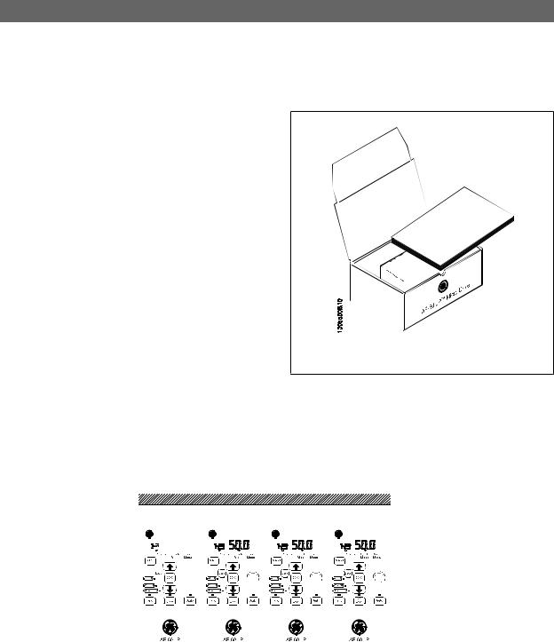
When unpacking the frequency converter, make sure that the unit is undamaged and complete. Check that the packaging contains the following:
• AF-60 LP™ Micro Drive
• Quick Guide
Illustration 2.1: Content of box.
2.2 Side-by-Side Installation
The frequency converter can be mounted side-by-side for IP 20 rating units and requires 100 mm or 3.94 inclearance above and below for cooling. Regarding surroundings in general, please see chapter 7. Specifications.
Illustration 2.2: Side-by-side installation.
DET-579A |
9 |
AF-60 LP™ Micro Drive Operating Instructions
2.3.1 Mechanical Dimensions
A template for drilling can be found on the flap of the packaging.
2 |
Illustration 2.3: Mechanical dimensions. |
|
|
Power (kW) |
|
|
|
Height (mm) |
|
Width (mm) |
Depth 1) (mm) |
Max. Weight |
||
Unit |
1 X 200-240 V |
3 X 200 -240 V |
3 X 380-480 V |
A |
A (incl. decoupling plate) |
a |
B |
b |
C |
Kg |
||
Size |
||||||||||||
|
|
|
|
|
|
|
|
|
|
|
||
M1 |
0.18 - 0.75 |
0.25 - 0.75 |
0.37 |
- 0.75 |
150 |
205 |
140.4 |
70 |
55 |
148 |
1.1 |
|
M2 |
1.5 |
1.5 |
1.5 |
- 2.2 |
176 |
230 |
166.4 |
75 |
59 |
168 |
1.6 |
|
M3 |
2.2 |
2.2 -3.7 |
3.0 |
- 7.5 |
239 |
294 |
226 |
90 |
69 |
194 |
3.0 |
|
M4 |
|
|
11.0-15.0 |
292 |
347.5 |
272.4 |
125 |
97 |
241 |
6.0 |
||
M5 |
|
|
18.5-22.0 |
335 |
387.5 |
315 |
165 |
140 |
248 |
9.5 |
||
1) For Keypad with potentiometer, please add 7.6 mm.
Table 2.1: Mechanical Dimensions
10 |
DET-579A |

AF-60 LP™ Micro Drive Operating Instructions
3 Electrical Installation
3.1 How to Connect
3.1.1 Electrical Installation in General
|
|
|
|
|
|
|
|
|
|
|
|
|
|
3 |
NB! |
|
|
|
|
|
|
|
|
|
|
|
|
||
All cabling must comply with national and local regulations on cable cross-sections and ambient temperature. Copper conductors required, (60-75° C) recom- |
|
|||||||||||||
mended. |
|
|
|
|
|
|
|
|
|
|
|
|
|
|
|
|
|
|
|
|
|
|
|
|
|
|
|
||
|
|
|
|
|
|
|
|
|
|
|
|
|
|
|
Details of terminal tightening torques. |
|
|
|
|
|
|
|
|
|
|
|
|||
|
|
|
|
|
|
|
|
|
|
|
|
|
|
|
|
|
|
Power (kW) |
|
|
|
|
Torque (Nm) |
|
|
|
|
|
|
|
|
|
|
|
|
|
|
|
|
|
|
|||
|
Unit Size |
1 x 200-240 V |
3 x 200-240 V |
3 x 380-480 V |
Line |
Motor |
DC connection/Brake |
Control Terminals |
Earth |
Relay |
|
|
|
|
|
M1 |
0.18 - 0.75 |
0.25 - 0.75 |
0.37 |
- 0.75 |
1.4 |
0.7 |
Spade1) |
0.15 |
3 |
0.5 |
|
|
|
|
M2 |
1.5 |
1.5 |
1.5 |
- 2.2 |
1.4 |
0.7 |
Spade1) |
0.15 |
3 |
0.5 |
|
|
|
|
M3 |
2.2 |
2.2 - 3.7 |
3.0 |
- 7.5 |
1.4 |
0.7 |
Spade1) |
0.15 |
3 |
0.5 |
|
|
|
|
M4 |
|
|
11.0-15.0 |
1.3 |
1.3 |
1.3 |
0.15 |
3 |
0.5 |
|
|
|
|
|
M5 |
|
|
18.5-22.0 |
1.3 |
1.3 |
1.3 |
0.15 |
3 |
0.5 |
|
|
|
|
1) Spade connectors (6.3 mm Faston plugs)
Table 3.1: Tightening of terminals.
DET-579A |
11 |
AF-60 LP™ Micro Drive Operating Instructions
3.1.2 Fuses
Branch circuit protection:
In order to protect the installation against electrical and fire hazard, all branch circuits in an installation, switch gear, machines etc., must be short-circuited and overcurrent protected according to national/international regulations.
|
Short circuit protection: |
|
|
|
|
|
|
|
|
|
||||
3 |
GE Drive is suitable for a circuit capable of supplying a maximum of 100,000 Arms (symmetrical), 480 V maximum. |
|
|
|
|
|||||||||
|
Overcurrent protection: |
|
|
|
|
|
|
|
|
|
||||
|
Provide overload protection to avoid overheating of the cables in the installation. Overcurrent protection must always be carried out according to national |
|||||||||||||
|
regulations. |
|
|
|
|
|
|
|
|
|
|
|||
|
Non UL compliance: |
|
|
|
|
|
|
|
|
|
||||
|
If UL/cUL is not to be complied with, GE recommends using the fuses mentioned in the below table, which will ensure compliance with EN50178/IEC61800-5-1: |
|||||||||||||
|
In case of malfunction, not following the fuse recommendation may result in damage to the frequency converter. |
|
|
|
|
|||||||||
|
|
|
|
|
|
|
|
|
|
|
|
|
|
|
|
|
|
|
|
|
|
|
Max. fuses UL |
|
|
|
|
|
|
|
|
|
|
|
Bussmann |
Bussmann |
Bussmann |
Littel fuse |
Ferraz- |
|
Ferraz- |
|
Max. fuses non UL |
|
|
|
|
|
|
Shawmut |
|
Shawmut |
|
|
|
||||
|
|
|
|
|
|
|
|
|
|
|
|
|||
|
|
|
1 X 200-240 V |
|
|
|
|
|
|
|
|
|
|
|
|
|
|
|
|
Type RK1 |
Type J |
Type T |
Type RK1 |
Type CC |
|
Type RK1 |
|
Type gG |
|
|
|
|
1/4 - 1/2 |
|
KTN-R15 |
JKS-15 |
JJN-15 |
KLN-R15 |
ATM-R15 |
A2K-15R |
16A |
|
||
|
|
|
1 |
|
KTN-R25 |
JKS-25 |
JJN-25 |
KLN-R25 |
ATM-R25 |
|
A2K-25R |
25A |
|
|
|
|
|
2 |
|
KTN-R35 |
JKS-35 |
JJN-35 |
KLN-R35 |
- |
|
A2K-35R |
35A |
|
|
|
|
|
3 |
|
KTN-R50 |
JKS-50 |
JJN-50 |
KLN-R50 |
- |
|
A2K-50R |
50A |
|
|
|
|
|
3 x 200-240 V |
|
|
|
|
|
|
|
|
|
|
|
|
|
|
1/3 |
|
KTN-R10 |
JKS-10 |
JJN-10 |
KLN-R10 |
ATM-R10 |
|
A2K-10R |
10A |
|
|
|
|
|
1/2 |
|
KTN-R15 |
JKS-15 |
JJN-15 |
KLN-R15 |
ATM-R15 |
|
A2K-15R |
16A |
|
|
|
|
|
1 |
|
KTN-R20 |
JKS-20 |
JJN-20 |
KLN-R20 |
ATM-R20 |
|
A2K-20R |
20A |
|
|
|
|
|
2 |
|
KTN-R25 |
JKS-25 |
JJN-25 |
KLN-R25 |
ATM-R25 |
|
A2K-25R |
25A |
|
|
|
|
|
3 |
|
KTN-R40 |
JKS-40 |
JJN-40 |
KLN-R40 |
ATM-R40 |
|
A2K-40R |
40A |
|
|
|
|
|
5 |
|
KTN-R40 |
JKS-40 |
JJN-40 |
KLN-R40 |
- |
|
A2K-40R |
40A |
|
|
|
|
|
3 x 380-480 V |
|
|
|
|
|
|
|
|
|
|
|
1/2 - 1 |
KTS-R10 |
JKS-10 |
JJS-10 |
2 |
KTS-R15 |
JKS-15 |
JJS-15 |
3 |
KTS-R20 |
JKS-20 |
JJS-20 |
4 |
KTS-R40 |
JKS-40 |
JJS-40 |
5 |
KTS-R40 |
JKS-40 |
JJS-40 |
7.5 |
KTS-R40 |
JKS-40 |
JJS-40 |
10 |
KTS-R40 |
JKS-40 |
JJS-40 |
15 |
KTS-R60 |
JKS-60 |
JJS-60 |
20 |
KTS-R60 |
JKS-60 |
JJS-60 |
25 |
KTS-R60 |
JKS-60 |
JJS-60 |
30 |
KTS-R60 |
JKS-60 |
JJS-60 |
KLS-R10 |
ATM-R10 |
A6K-10R |
10A |
KLS-R15 |
ATM-R15 |
A2K-15R |
16A |
KLS-R20 |
ATM-R20 |
A6K-20R |
20A |
KLS-R40 |
ATM-R40 |
A6K405R |
40A |
KLS-R40 |
ATM-R40 |
A6K-40R |
40A |
KLS-R40 |
- |
A6K-40R |
40A |
KLS-R40 |
- |
A6K-40R |
40A |
KLS-R60 |
- |
A6K-60R |
63A |
KLS-R60 |
- |
A6K-60R |
63A |
KLS-R60 |
- |
A6K-60R |
80A |
KLS-R60 |
- |
A6K-60R |
80A |
Table 3.2: Fuses
12 |
DET-579A |
AF-60 LP™ Micro Drive Operating Instructions
3.1.3 EMC-Correct Installation
Following these guidelines is advised, where compliance with EN 61000-6-3/4, EN 55011 or EN 61800-3 First environment is required. If the installation is in EN 61800-3 Second environment, then it is acceptable to deviate from these guidelines. It is however not recommended.
Good engineering practice to ensure EMC-correct electrical installation:
• |
Use only braided screened/armoured motor cables and control cables. |
3 |
|
The screen should provide a minimum coverage of 80%.The screen material must be metal, not limited to but typically copper, aluminium, steel or lead. |
There are no special requirements for the mains cable.
•Installations using rigid metal conduits are not required to use screened cable, but the motor cable must be installed in conduit separate from the control and mains cables. Full connection of the conduit from the drive to the motor is required. The EMC performance of flexible conduits varies a lot and information from the manufacturer must be obtained.
•Connect the screen/armour/conduit to earth at both ends for motor cables and control cables.
•Avoid terminating the screen/armour with twisted ends (pigtails). Such a termination increases the high frequency impedance of the screen, which reduces its effectiveness at high frequencies. Use low impedance cable clamps or glands instead.
•Ensure good electrical contact between the de-coupling plate and the metal chassis of the frequency converter, see Instruction
•Avoid using unscreened/unarmoured motor or control cables inside cabinets housing the drive(s), where possible.
3.2 Mains Connection
3.2.1 Connecting to Mains
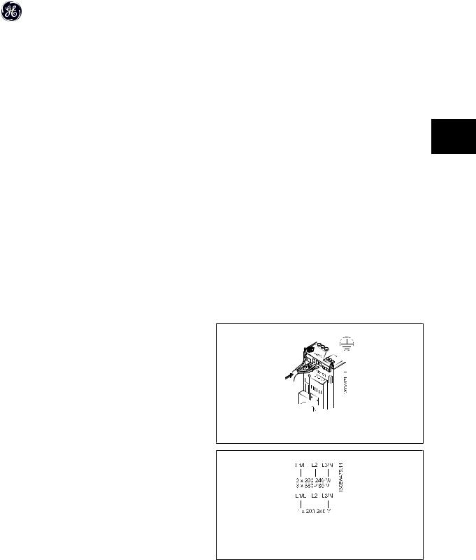
Step 1: First mount earth cable.
Step 2: Mount wires in terminals L1/L, L2 and L3/N and tighten.
For 3-phase connection, connect wires to all three terminals.
For single-phase connection, connect wires to terminals L1/L and L3/N.
Illustration 3.1: Mounting of earth cable and mains wires.
Illustration 3.2: Three-phase and single-phase wire connections.
DET-579A |
13 |
AF-60 LP™ Micro Drive Operating Instructions
3.3 Motor Connection
3.3.1 How to Connect the Motor
See the chapter Specifications for correct dimensioning of motor cable cross-section and length.
3 |
• |
Use a shielded/armored motor cable to comply with EMC emission specifications, and connect this cable to both the decoupling plate and the motor |
|
metal. |
|
|
• |
Keep motor cable as short as possible to reduce the noise level and leakage currents. |
|
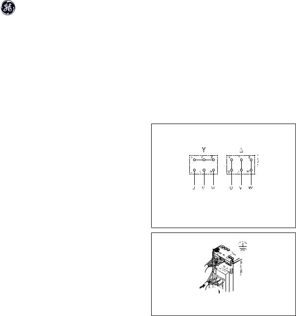
All types of three-phased asynchronous standard motors can be connected to the frequency converter. Normally, small motors are star-connected (230/400 V, /Y). Large motors are delta-connected (400/690 V, /Y). Refer to motor nameplate for correct connection and voltage.
Step 1: First, mount the earth cable.
Step 2: Connect wires to terminals either in star or delta-connection. See motor nameplate for further information.
Illustration 3.3: Star and delta connections.
Illustration 3.4: Mounting of earth cable and motor wires.
14 |
DET-579A |
AF-60 LP™ Micro Drive Operating Instructions
For EMC correct installation, use optional de-coupling plate, see chapter Options for frequency converter.
3
Illustration 3.5: Frequency converter with de-coupling plate
3.4 Control Terminals
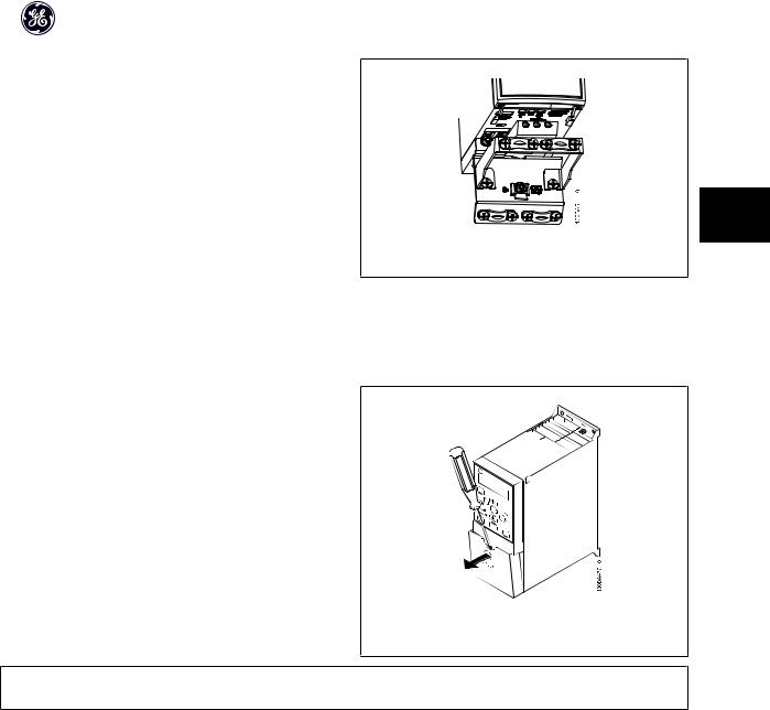
3.4.1 Access to Control Terminals
All control cable terminals are located underneath the terminal cover in front of the frequency converter. Remove the terminal cover using a screwdriver.
Illustration 3.6: Removing terminal cover.
NB!
See back of terminal cover for outlines of control terminals and switches.
DET-579A |
15 |
AF-60 LP™ Micro Drive Operating Instructions
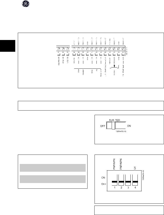
3.4.2 Connecting to Control Terminals
This illustration shows all control terminals of the frequency converter. Applying Start (term. 18) and an analog reference (term. 53 or 60) make the frequency converter run.
3
Illustration 3.7: Overview of control terminals in PNP-configuration and factory setting.
3.5 Switches
NB!
Do not operate switches with power on the frequency converter.
Bus termination:
Switch BUS TER pos. ON terminates the RS485 port, terminals 68, 69. See power circuit drawing.
Default setting = Off.
Illustration 3.8: S640 Bus termination.
S200 Switches 1-4:
Switch 1: *OFF = PNP terminals 29
ON = NPN terminals 29
Switch 2: *OFF = PNP terminal 18, 19, 27 and 33
ON = NPN terminal 18, 19, 27 and 33
Switch 3: No function
Switch 4: *OFF = Terminal 53 0 - 10 V
ON = Terminal 53 0/4 - 20 mA
* = default setting
Table 3.3: Settings for S200 Switches 1-4
Illustration 3.9: S200 Switches 1-4.
NB!
Parameter 6-19 must be set according to Switch 4 position.
16 |
DET-579A |

AF-60 LP™ Micro Drive Operating Instructions
3.6 Power Circuit - Overview
3.6.1 Power Circuit - Overview
3
Illustration 3.10: Diagram showing all electrical terminals.
* Brake (BR+ and BR-) are not applicable for Unit Size M1.
Brake resistors are available from GE.
Improved power factor and EMC performance can be achieved by installing optional GE line filters.
GE power filters can also be used for load sharing.
DET-579A |
17 |

AF-60 LP™ Micro Drive Operating Instructions
3.6.2 Load sharing/Brake
Use 6.3 mm insulated Faston Plugs designed for high voltage for DC (Load Sharing and brake).
|
|
Load sharing: Connect terminals UDCand UDC/BR+. |
|
|
Brake: Connect terminals BRand UDC/BR+ (Not applicable for Unit Size M1). |
|
|
|
3 |
|
|
|
Note that voltage levels of up to 850 V DC may occur between terminals |
|
|
|
UDC+/BR+ and UDC-. Not short circuit protected. |
|
|
|
|
|
|
18 |
DET-579A |

AF-60 LP™ Micro Drive Operating Instructions
4 Programming
4.1 How to Programme
4.1.1 Programming with DCT-10 Set-up Software
The frequency converter can be programmed from a PC via RS485 com-port by installing the DCT-10 Set-up Software.
This software can be downloaded from the GE Web site: www.geelectrical.com/drives
4
4.1.2 Programming with the Keypad
The Keypad is divided into four functional groups:
1.Numeric display.
2.Menu key.
3.Navigation keys.
4.Operation keys and indicator lights (LEDs).
NB!
Parameters should be changed in numerical order. Certain parameter values are affected by preceding changes.
Illustration 4.1: Keypad with potentiometer
The display:
A number of information can be read from the display.
Set-up number shows the active set-up and the edit set-up. If the same setup acts as both active and edit set-up, only that set-up number is shown (factory setting).
When active and edit set-up differ, both numbers are shown in the display (Setup 12). The number flashing, indicates the edit set-up.
Illustration 4.2: Indicating Set-up
DET-579A |
19 |
AF-60 LP™ Micro Drive Operating Instructions
The small digits to the left are the selected parameter number.
The large digits in the middle of the display show the value of the selected 4 parameter.
The right side of the display shows the unit of the selected parameter. This can be either Hz, A, V, kW, HP, %, s or RPM.
Motor direction is shown to the bottom left of the display - indicated by a small arrow pointing either clockwise or counterclockwise.
Illustration 4.3: Indicating selected par. no.
Illustration 4.4: Indicating value of selected par.
Illustration 4.5: Indicating unit of selected par.
Illustration 4.6: Indicating motor direction
Use the [MENU] key to select one of the following menus:
Status Menu:
The Status Menu is either in Readout Mode or Hand Mode. In Readout Mode the value of the currently selected readout parameter is shown in the display.
In Hand Mode the local Keypad reference is displayed.
Quick Menu:
Displays Quick Menu parameters and their settings. Parameters in the Quick Menu can be accessed and edited from here. Most applications can be run by setting the parameters in the Quick Menus.
Main Menu:
Displays Main Menu parameters and their settings. All parameters can be accessed and edited here. A parameter overview is found later in this manual.
Indicator lights:
•Green LED: The frequency converter is on.
•Yellow LED: Indicates a warning. Please see section Troubleshooting
•Flashing red LED: Indicates an alarm. Please see section Troubleshooting
20 |
DET-579A |
AF-60 LP™ Micro Drive Operating Instructions
Navigation Keys:
[Back]: For moving to the previous step or layer in the navigation structure.
Arrows [▲] [▼]: For maneuvering between parameter groups, parameters and within parameters. [OK]: For selecting a parameter and for accepting changes to parameter settings.
Operation Keys:
A yellow light above the operation keys indicates the active key.
[Hand ]: Starts the motor and enables control of the frequency converter via the Keypad. [Off/Reset]: The motor stops except in alarm mode. In that case the motor will be reset.
[Auto ]: The frequency converter is controlled either via control terminals or serial communication.
[Potentiometer] Keypad: The potentiometer works in two ways depending on the mode in which the frequency converter is running.
In Auto Mode the potentiometer acts as an extra programmable analog input. 4 In Hand Mode the potentiometer controls local reference.
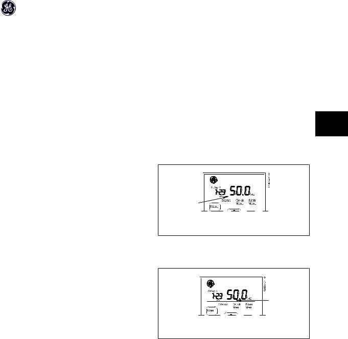
4.2 Status Menu
After power up the Status Menu is active. Use the [MENU] key to toggle between Status, Quick Menu and Main Menu.
Arrows [▲] and [▼] toggles between the choices in each menu.
The display indicates the status mode with a small arrow above “Status”.
Illustration 4.7: Indicating Status mode
4.3 Quick Menu
The Quick Menu gives easy access to the most frequently used parameters.
1.To enter the Quick Menu, press [MENU] key until indicator in display is placed above Quick Menu.
2.Use [▲] [▼] to select either QM1 or QM2, then press [OK].
3.Use [▲] [▼] to browse through the parameters in the Quick Menu.
4.Press [OK] to select a parameter.
5.Use [▲] [▼] to change the value of a parameter setting.
6.Press [OK] to accept the change.
7.To exit, press either [Back] twice to enter Status, or press [Menu] once to enter Main Menu.
Illustration 4.8: Indicating Quick Menu mode
DET-579A |
21 |
 Loading...