


GE
Industrial Solutions
Limitamp® AR: Installation Guide
CR 194 One/Two-High Vacuum Limitamp® AR Control
imagination at work
Table of Contents |
|
Introduction............................................................................................... |
3 |
Opening High Voltage Door................................................................. |
3 |
High-Voltage Door Latches.................................................................. |
4 |
Isolation Switch Handle to Contactor |
|
Mechanical Interlock.............................................................................. |
5 |
High-Voltage Door Defeater Latch.................................................... |
6 |
Low-Voltage Box Wiring Details......................................................... |
7 |
Plenum Installation Guide.................................................................... |
7 |
Turned Extension Plenum Installation Guide (Front/Rear)...... |
10 |
Turned Extension Plenum Installation Guide (Top/Bottom).... |
11 |
Limitamp AR Extension Plenum....................................................... |
13 |
Extension Plenum - General Guidelines........................................ |
14 |
Cable Entry From Top or Bottom..................................................... |
16 |
Dimensions............................................................................................. |
16 |
CR 194 One/Two-High Vacuum Limitamp® AR Control |
Page 2 |
Introduction
GE’s Limitamp® AR is the solution for applications where an extra margin of protection is essential. It meets the IEEE C37.20.7 Type 2B and IEC 62271-200, TYPE-A standards and is available in oneand two-high versions of FVNR motor starters, rated for 2.4-7.2kV-400A, 5kV-800A.
This instruction book is to be used in conjunction with GEH6263 (Two high vacuum equipment), GEH-5306 (vacuum contactor) and GEH 5396B (800A) instructions.
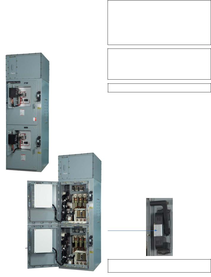
Figure 1. 36” wide Two-High AR FVNR starter with low-voltage doors open.
WARNING: Before any adjustments, servicing, parts replacement or any other act is performed requiring physical contact with the electrical working components or wiring of this equipment, all power must be removed and locked off from all sources and all attached rotating equipment must have come to a complete stop. User personnel must be completely familiar with the following operating and maintenance instructions before attempting to service this equipment.
WARNING: The vacuum interrupter integrity test should be performed before the high voltage vacuum contactors are energized for the first time and each time the contactors are returned to service after maintenance, adjustment or repair. Failure to perform this test may result in serious injury or death.
CAUTION: Product is not intended for nuclear use.
Figure 2. 36” wide Two-High AR FVNR starter with high-voltage doors open.
Opening High-Voltage Door
The high-voltage doors on the CR194 Two-High Vacuum Limitamp AR are mechanically interlocked to prevent the opening of the doors, when equipment is energized. For safe opening of high-voltage door, follow the step-by-step procedure as mentioned below.
Step 1: Push in the handle latch release and rotate the isolation switch handle to the full “OFF” position. The latch release must pop back out. See figure 3.
Step 2: Rotate the handle (Black color handle) down with a rapid positive motion, to bring it to “OFF” Position.
Step 3: Rotate the high-voltage door latch handle (silver color) 90° in the counter-clockwise direction to disengage the multi latches on the inside of the door.
Step 4: Turn all flange nuts simultaneously until disengaged from hat brackets.
Step 5: The high-voltage door may then be opened by pulling out on the latch handle.
Figure 3. Push in the handle latch
WARNING: Confirm that equipment is de-energized before opening the high-voltage doors.
CR 194 One/Two-High Vacuum Limitamp® AR Control |
Page 3 |
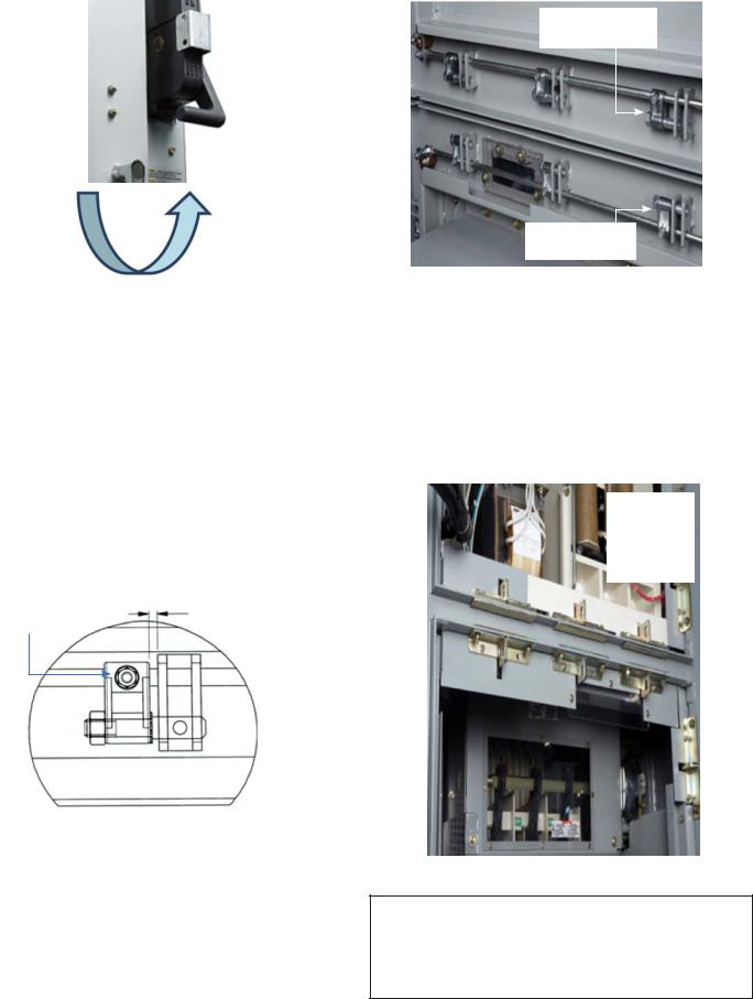
Figure 4. Rotating the high-voltage door latch handle.
Latch Handle
High-Voltage Door Latches
The Limitamp AR design uses special high strength door latch parts to keep the door closed during an arcing event. All of the latches must be properly engaged for the product to function properly. On the outside of the high-voltage door there is a door latch operating handle. Rotating this handle operates all of the latch locking pins at one time.
The door latch locking pins are all adjusted prior to shipping from the factory. If any of the door latch pins are moved or replaced make sure they are adjusted per the sketch below.
Make sure to tighten the locking stud on the locking pin bridge.
When the door handle is in the locked position adjust locking pin bridge to provide a 0.150” gap between the bridge and the welded “U” fork on the door.
.150
Locking Stud
Figure 5. View to show gap between locking pin bridge and “U” fork on the door.
Locking Pins in
Unlocked Position
Locking Pins in
Locked Position
Figure 6. View of locking pins on high-voltage door.
The mating part of the latch system is shown in the Figure 7 below. The enclosure side latch parts are mounted to the frame using a stud plate that passes through the flange of the case. The latch parts can be adjusted in all directions using the slots in the latch parts and special spacers that mount under the latch parts. The latch parts should be adjusted so the locking pins on the door engage the open slot on the case side latch part. The nominal position for the latch part is flush with the front edge of the enclosure flange.
Latch Plates
Should Be
Flush With
Front Flange
of Enclosure
Figure 7. View of enclosure mounted latch parts.
WARNING: Barriers or enclosure door latch parts removed to service the equipment must be re-installed in the exact location for safe operation. Not complying with this instruction could lead to serious injury. Mark the location of these items with the ink for ease of re-assembly.
CR 194 One/Two-High Vacuum Limitamp® AR Control |
Page 4 |

Isolation Switch Handle to Contactor Mechanical Interlock
The Limitamp AR two-high vacuum starter is equipped with a quick-make, quick-break isolation switch in each starter. This isolation switch is not designed to make or break motor load current. To insure that the isolation switch handle cannot be operated when the contactor is energized, a mechanical interlock mechanism is provided between the contactor and the isolation switch handle. Operation of this mechanical interlock for each starter should be checked per the following procedure.
WARNING: Confirm the equipment is de-energized before performing this check.
Adjustment Nuts On
the Interlock Assembly
Figure 8. View of the contactor to isolation switch mechanical interlock at the vacuum contactor.
Figure 9. Adjusting connecting rod
Step 1: Adjust the nuts to shift the connecting rod position as shown in Figure 10.
Step 2: With the contactor open the connecting rod should be adjusted up to a point where the pusher will pass through the round hole in the connecting rod.
Step 3: Once adjusted tighten the two nuts against the block.
Connecting Rod |
|
Pusher Rod |
|
|
|
Figure 10. Showing how pusher is unblocked when the contactor is open.
Pusher Rod
Blocked
Figure 11. Showing how pusher is blocked when the contactor is closed.
To verify that the interlock is properly adjusted push down on the top of the contactor moving armature and hold it down. Now attempt to press the handle latch release (pusher). The mechanical interlock should prevent the handle release from going in and prevent the handle from being moved.
CR 194 One/Two-High Vacuum Limitamp® AR Control |
Page 5 |
High-Voltage Door Defeater Latch
WARNING: The following steps should be taken only as a last resort to enter a malfunctioning controller. It is imperative that all power to main bus be removed before proceeding.
IN CASE OF EMERGENCY, remove all power to the controller, then the high-voltage door may be opened with the contactor in the closed position and with the isolation switch closed, by following the procedure listed below.
WARNING: Do not proceed unless all power to the controller is removed. In this situation, doors must not be opened with power connected to the bus.
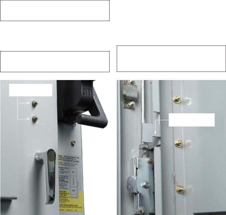
Step 1: Remove the door interlock defeater locking nuts as shown in Figure 12.
Step 2: Rotate the door latch operating handle 90° counterclockwise to disengage the multiple door latches on the inside of the high-voltage door.
Step 3: Turn all flange nuts simultaneously until disengaged from hat brackets.
Step 4: The high-voltage door should be able to be opened by pulling out on the silver handle. As you pull on the door, the door interlock defeater will pull away from the door.
WARNING: Defeating high-voltage door interlock leaves the power fuses and contactor connected to the bus. The bus power must remain de-energized while the high-voltage door is open.
Door Interlock Defeater
Locking Nuts
Door Interlock Defeater
Figure 12. View showing door interlock defeater locking nuts. |
Figure 13. View showing door interlock defeater. |
CR 194 One/Two-High Vacuum Limitamp® AR Control |
Page 6 |
 Loading...