


PowerVac PV-VL 13.8-1000-0 a
gg
GEH-6468A Instructions
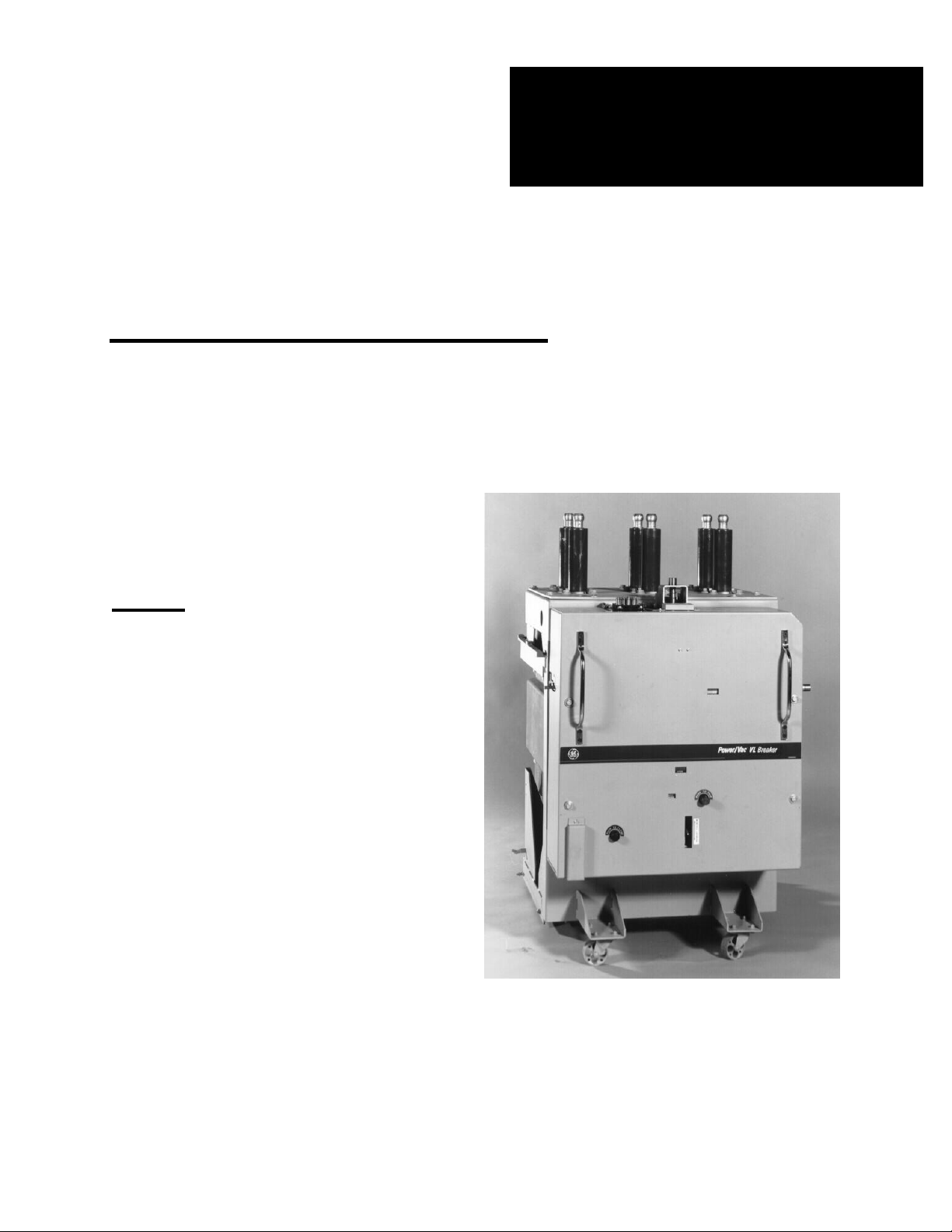
GE PowerVac
®
VL
Vacuum Circuit Breaker
TYPE
PV-VL 13.8-500-0 and -1
PV-VL 13.8-750-0 and -1
PV-VL 13.8-1000-0 and -1
With ML-18VL Mechanism

Page 2 GEH 6468A - Power/Vac VL Breaker

GEH 6468A - Power/Vac VL Breaker Page 3
CONTENTS
1. INTRODUCTION 5
11.3 CONTACT GAP 30
1.1 SAFETY 5 11.4 CLOSE COIL PLUNGER GAP 31
11.5 TRIP COIL PLUNGER GAP 31
2. DESCRIPTION 5
11.6 CONTROL SWITCH ADJUSTMENT 31
3. RECEIVING, HANDLING AND STORAGE 6 12. ELECTRICAL CHECKS 31
3.1 RECEIVING 6 12.1 ELECTRICAL OPERATION 31
3.2 HANDLING 6 12.2 HIGH-POTENTIAL TEST 31
3.3 STORAGE 6 12.2.1 PRIMARY CIRCUIT 31
3.4 PACKING LIST 6 12.2.2 SECONDARY CIRCUIT 32
12.3 PRIMARY CIRCUIT RESISTANCE 32
4. INITIAL INSTALLATION PROCEDURES 7
12.4 VACUUM INTEGRITY TEST 32
4.1 DOOR WIRING INTERFERENCE 7 12.5 INSULATION TESTS 33
4.2 POSITIVE INTERLOCK
TEST PROCEDURES 7
13. CHECKING AND INSTALLATION 33
4.3 BY-PASS KIT INSTALLATION 7
4.4 CHECKING FOR PROPER INTER-
14. MAINTENANCE 33
LOCK AND TRIP FREE FUNCTIONS 14.1 GENERAL 33
BEFORE LOWERING THE BREAKER 14.2 SERVICE CONDITIONS 34
FROM THE ELEVATED POSITION 8 14.3 FAULT INTERRUPTION 34
14.4 CONTACT EROSION 34
5. ADJUSTMENTS TO BREAKERS /
14.5 TRANSFER FINGER WEAR 35
SWITCHGEAR INTERFACES 8
14.6 MECHANISM 35
5.1 STATIONARY AUXILIARY SWITCH 8 14.7 PRIMARY INSULATION PARTS 35
5.2 PRIMARY CONTACT PENETRATION 9 14.8 LUBRICATION 35
5.3 POSITIVE INTERLOCK 9 14.9 RECOMMENDED MAINTENANCE 35
5.4 SECONDARY COUPLER 10
5.5 SPRING DISCHARGE CAM 10
15. TIMING 36
5.6 STOPS 10
5.7 GROUND 10
16. OPENING AND CLOSING SPEED 36
5.8 POSITION SWITCH 10
17. REPAIR AND REPLACEMENT 36
6. TYPICAL WIRING DIAGRAMS 11
17.1 GENERAL 36
17.2 REPLACING INTERRUPTERS 36
7. FEATURES 27
17.3 PRIMARY DISCONNECTS 37
7.1 SAFETY PRECAUTIONS 27 17.4 MECHANISM 37
7.2 INTERLOCKS 27 17.5 CONTROL SWITCHES 37
7.2.1 RATING INTERFERENCE PLATE 27 17.6 TRIP COIL REPLACEMENT 37
7.2.2 POSITIVE INTERLOCK SYSTEM 27 17.7 CLOSING COIL REPLACEMENT 37
7.2.3 SPRING DISCHARGE SYSTEM 27 17.8 AUXILIARY SWITCH
REPLACEMENT
37
17.9 MOTOR REPLACEMENT 38
8. OPERATION 28
17.10 “Y” RELAY REPLACEMENT 38
8.1 CLOSE SPRING CHARGING 28
8.2 CLOSING OPERATION 29
18. RENEWAL PARTS 38
8.3 OPENING OPERATION 29 18.1 ORDERING INSTRUCTIONS 38
8.4 TRIP-FREE OPERATION 29
19. MECHANICAL ADJUSTMENTS 38
9. CONTROL CIRCUIT 29
19.1 GENERAL 38
19.2 WIPE ADJUSTMENT 38
10. MECHANICAL CHECK AND
19.3 CONTACT GAP ADJUSTMENT 39
SLOW CLOSE 29
19.4 TRIP COIL PLUNGER 39
10.1 VISUAL INSPECTION 29 19.5 CLOSE COIL PLUNGER 39
10.2 CLOSING SPRING CHARGING 29 19.6 CLOSE SPRING INTERLOCK 39
10.3 CLOSING SPRING GAG 30 19.7 POSITIVE INTERLOCK 39
10.4 SLOW CLOSING 30
10.5 GAG TOOL REMOVAL 30
11. DIMENSIONAL CHECKS 30
LIST OF ILLUSTRATIONS 4
11.1 PRIMARY CONTACT EROSION 30
INDEX
70
11.2 SPRING WIPE 30 STATIONARY CUBICLE INFORMATION 62

Page 4 GEH 6468A - Power/Vac VL Breaker
LIST OF ILLUSTRATIONS
FIGURE PAGE
1 INTERIOR VIEW OF STATIONARY CUBICLE 12
2 INTERLOCK MODIFICATION 13
3 MOTOR OPERATOR SWITCH ACTUATOR 14
4 ELEVATING MOTOR TROUBLESHOOTING 15
5 SCHEMATIC DIAGRAM - VERTICAL LIFT DRIVE MECHANISM 16
6 STATIONARY STRUCTURE WIRING 17
7 BY-PASS KIT INSTALLATION 18
8 BREAKER WIRE DIAGRAM (typical) OLD MS MECHANISM 19
9 BREAKER WIRE DIAGRAM (typical) OLD ML MECHANISM 20
10 ADJUSTMENT OF PLUNGER INTERLOCK 21
11 PRIMARY CONTACT PENETRATION 22
12 POSITIVE INTERLOCK ROLLER 23
13 POSITIVE INTERLOCK 1000 MVA UNITS 24
14 POSITIVE INTERLOCK M-26 UNITS 25
15 POSITIVE INTERLOCK M-36 UNITS 26
16 FRONT VIEW WITH FRONT COVER 44
17 FRONT VIEW WITHOUT COVER 45
18 MANUAL CHARGING HANDLE 46
19 CLOSING SPRING GAG ACCESS 47
20 TOGGLE LINKAGE POSITIONS 48-50
21 CONTACT EROSION INDICATOR 51
22 OPERATING ROD ASSEMBLY 52
23 ML-18VL MECHANISM 53-54
24 TRIP COIL LINKAGE 55
25 CLOSE COIL AND LINKAGE 56
26 FRONT VIEW OF ML-18VL MECHANISM 57
27 CONTACT GAP 58
27a CONTACT GAP ADJUSTMENT 59
28 FLEX CABLE CONNECTION 60
29 SAMPLE OPERATING SPEED GRAPHS 61
30 CLOSE COIL PLUNGER GAP 62
31 CONTROL SWITCHES 63
32 TRIP COIL PLUNGER GAP 64
33 SPRING WIPE 64
INDEX 70
TROUBLE REPORTING FORM 68-69
TABLE OF MEASUREMENTS AND ADJUSTMENTS 40
ADDENDUM TO GEH-1802 (CUBICLE) 62

GEH 6468A - Power/Vac VL Breaker Page 5
These instructions do not purport to cover all details or variations in equipment nor to provide for every
possible contingency to be met in connection with installation, operation or maintenance. Should further
information be desired or should particular problems arise which are not covered sufficiently for the
purchaser's purposes, the matter should be referred to the Seller.
To the extent required, the products described herein meet applicable ANSI, IEEE and NEMA standards, but no
such assurance is given with respect to local codes and ordinances because they vary greatly.
POWER/VAC
®
VL
VACUUM CIRCUIT BREAKER
WITH ML-18VL MECHANISM
1. INTRODUCTION
1.1. SAFETY
IT IS IMPERATIVE THAT ALL PERSONNEL
ASSOCIATED WITH THIS EQUIPMENT READ
AND COMPLETELY UNDERSTAND THE
WARNINGS LOCATED THROUGHOUT THIS
INSTRUCTION BOOK. FAILURE TO DO SO
CAN RESULT IN DAMAGE TO PROPERTY,
PERSONAL INJURY OR DEATH.
Each user must maintain a safety program for the
protection of personnel, as well as other equipment,
from the potential hazards associated with
electrical equipment.
The following requirements are intended to
augment the user’s safety program but NOT
supplant the user’s responsibility for devising a
complete safety program. The following basic
industry practiced safety requirements are
applicable to all major electrical equipment such as
switchgear or switchboards. GE neither condones
nor assumes any responsibility for practices which
deviate from the following:
1. ALL CONDUCTORS MUST BE ASSUMED TO
BE ENERGIZED UNLESS THEIR POTENTIAL
HAS BEEN MEASURED AS GROUND AND
ADEQUATE CAPACITY GROUNDING AS-
SEMBLIES HAVE BEEN APPLIED TO PRE-
VENT ENERGIZING. Many accidents have
been caused by unplanned energization from
non-recognized back feeds, equipment
malfunc-tions, and from a wide variety of
sources.
2. It is strongly recommended that all equipment
be completely de-energized, verified to be
“dead”, then grounded with adequate capacity
grounding assemblies prior to any
maintenance. The rounding cable assemblies
must be able to withstand energizing fault
levels so that protective equipment may clear
the circuit safety. Additional discussion on this
concept is covered in Chapter 20 of ANSI/
NFPA 70B, Electrical Equipment Maintenance.
3. Although interlocks to reduce sone of the risks
are provided, the individual’s actions while
performing service of maintenance are
essential to prevent accidents. Each person’s
know-ledge; mental awareness; and planned
and executed actions often determine if an
accident will occur. The most important
method of avoiding accidents is for all
associated personnel to carefully apply a
thorough understanding of the specific
equipment from the viewpoints of its purpose,
its construction, its operation and the situations
which could be hazardous.
All personnel associated with installation, operation
and maintenance al electrical equipment, such as
power circuit breakers and other power handling
equipment, must be thoroughly instructed, with
periodic retraining, regarding equipment in general
as well as the particular model of equipment which
they are working.
Instruction books, actual devices and appropriate
safety and maintenance practices such as OSHA
publications, National Electric Safety Code (ANSI)
C2), National Electric Code, and National Fire
Protection Association (NFPA) 70B Electrical
Equipment Maintenance must be closely studied
and followed. During actual work, supervision
should audit practices to assure conformance.
It is strongly recommended that all equipment be
completely de-energized, verified to be “dead”,
then grounded with adequate capacity grounding
assemblies prior to any maintenance.
2. DESCRIPTION
The PowerVac
®
VL vacuum circuit breaker is a
vertical lift, removable and interchangeable inter-
rupting element, for use in metal-clad switchgear to
provide protection and control of electrical
apparatus and power systems. The PowerVac
®
VL
Type PV-VL circuit breaker with ML-18VL mechan-

Page 6 GEH 6468A - Power/Vac VL Breaker
ism is available in continuous current ratings of
1200, 2000 and 3000 amperes in accordance with
industry standards. In addition, extended ratings of
3500, (not part of the original Magnablast offering)
and 4000 amperes is available as well as a 5000
ampere fan cooled option. Refer to the breaker
nameplate for complete rating information of any
particular breaker. The nameplate also describes
the control power requirements for that breaker.
The application of a breaker must be such that its
voltage, current and interrupting ratings are never
exceeded. Since this book is written to include all
ratings of the breaker, as well as several design
variations, the instructions will be of a general
character and all illustrations will be typical unless
otherwise specified.
3. RECEIVING, HANDLING AND STORAGE
3.1. RECEIVING
Each breaker is carefully inspected before
shipment. Immediately upon receipt of the circuit
breaker, an examination should be made for any
damage sustained in transit. If injury or rough
handling is evident, a claim should be filed
immediately with the transportation company, and
the nearest GE Sales Office should be notified.
3.2. HANDLING
It is expected that care will be exercised during the
unpacking and installation of breakers so that no
damage will occur from careless or rough handling,
or from exposure to moisture or dirt. Loose parts
associated with the breaker are sometimes
included in the same crate. Check all parts against
the packing list to be sure that no parts have been
overlooked.
3.3. STORAGE
It is recommended that the breaker be put into
service immediately in its permanent location. If
this is not possible, the following precautions must
be taken to assure the proper storage of the
breaker.
The breaker should be stored in a clean location,
free from corrosive gases or fumes. Particular care
should be taken to protect the equipment from
mois- ture and cement dust, as this combination
has a very corrosive effect on many parts.
Breakers should be carefully protected against con-
densation, preferably by storing in a warm, dry
room of moderate temperature such as 40 to 100°
F. High humidity may have an adverse effect on
the insulating parts and should be avoided.
Circuit breakers for outdoor metal-clad switchgear
should be stored in the equipment only when power
is available and the heaters are in operation to
prevent condensation.
Rollers, latches, etc. of the operating mechanism
should be coated with GE part No. 0282A2048P009
(Mobil 28 red) grease to prevent rusting.
If the breaker is stored for any length of time, it
should be inspected periodically to see that
corrosion has not started. Should the breaker be
stored under unfavorable atmospheric conditions, it
should be serviced before being placed on line.
3.4 PACKING LIST
With your breaker, you should have received:
1. Manual charging handle. (Part No.
0282A7227P001)
2. Gag tool. (Part No. 0209B8043G003)
3. Breaker Instruction Book - Contact your GE
office for additional copies or verification of
present revision.
4. (1) piece of edge protector (See section 4.1)
5. (12) wire ties. (See section 4.1)
6. Lower blocking plate and screws for lower
notch in positive interlock cam plate in existing
breaker cell units. (Kit # 254-089) NOTE: This
assembly eliminates the test provision for
closing the breaker in the cabinet, except in the
“connect” position, as has been recommended
to improve safety of the VL equipment.
7. Existing unit wiring and device WARNING
NOTICE sheet.
8. (1) GE tool parts kit (0282A3060G003) with
each breaker order of single or multiple
breakers.
9. A spring discharge interlock cam - to be
installed if none exists in your switchgear cell.
NOTE: Customer option to implement, if
required.
10. GE grease Part No. 0282A2048P009.
Contact your local GE office if you have not
received the above materials.

GEH 6468A - Power/Vac VL Breaker Page 7
4. INITIAL INSTALLATION PROCEDURES
Although GE has made every effort to assure
interchangability and satisfactory interface with
existing equipment, older equipment and field
modifications made over the years, may require
additional procedures before the new vacuum
breaker can be installed in the cubicle.
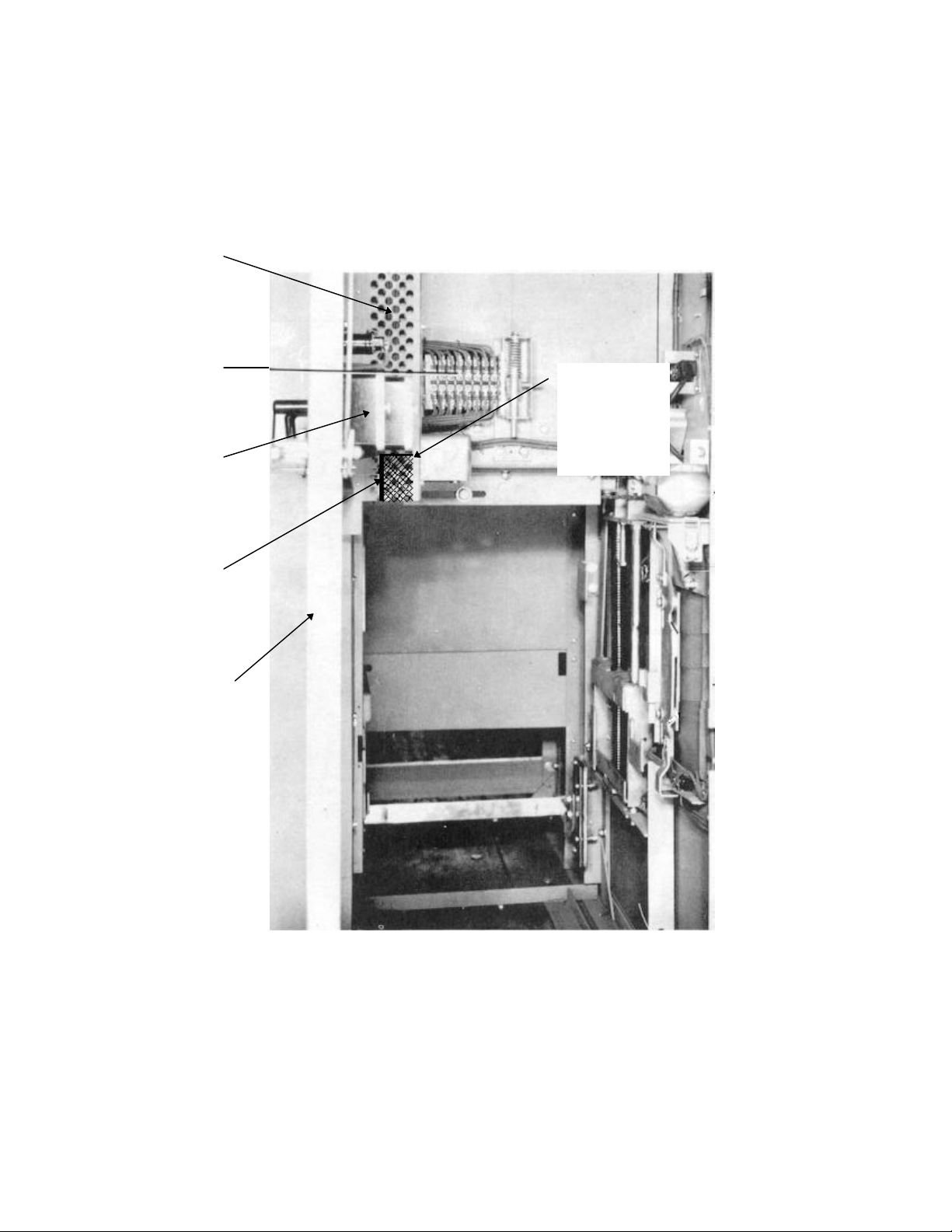
4.1 DOOR WIRING INTERFERENCE
In some of the older GE Metal-Clad switchgear
units, the wiring from the door to the stationary
structure was run through a perforated steel wire
assembly grill. (Figure 1.)
As the new replacement breaker is elevated, the
front cover MAY interfere with the subject wiring
grill, approximately 4” to 6” before the final
connected position.
The front cover shield on the replacement breaker
is wider than all previous AM breaker units. Due to
the large forces required to operate the existing
stationary auxiliary switches, the operating
mechanism cannot be decreased in width.
If this condition exists, use the modification kit
shipped with the breaker and make the following
modifications to the switchgear cubicle.
1. Cut out the bottom section of the grill as shown
in figure 1 on page 12.
2. Cover the sharp edges with the edge protector
furnished with the breaker accessories.
3. Fold any wire back and re-tie with the furnished
wire ties.
4. Elevate the replacement breaker in accordance
with the instructions.
4.2 POSITIVE INTERLOCK TEST
PROCEDURES
The positive interlock system functions to prevent
closing the breaker contacts when the breaker is
being raised or lowered and prevents raising or
lowering the breaker when the breaker contacts are
closed. In most AM breaker Metal-Clad Switchgear
units, there is a breaker “Test Position” which
allows you to functionally test the breaker without
connecting to the bus. This position is usually about
5” out from the breaker being fully inserted into the
cubicle. When in the “test position”, a secondary
coupler cable must be used to connect the
secondary control circuits since the breaker is
fully lowered position.
The lower “Vee” notch in the positive interlock cam
plate allows closing and opening the breaker
electrically.
FOR IMPROVED SAFETY, IT IS
RECOMMENDED THAT THE ABILITY TO
FUNCTIONALLY OPER-ATE THE BREAKER IN
THE “TEST” POSITION BE ELIMINATED AND
THAT BREAKER FUNC-TIONAL TESTING BE
PERFORMED WITH THE BREAKER
COMPLETELY REMOVED FROM THE CUBICLE.
4.3 BY-PASS KIT INSTALLATION
(See Figures 2 & 7).
The ability to electrically close and open the
breaker in the “Test Position” is eliminated by
covering the lower Vee notch in the positive
interlock cam plate. Materials for accomplishing
this modification are provided in Kit #254-089
furnished with the new vacuum breaker. This by-
pass kit should be in-stalled on GE breaker cubicles
that have a lower interlock roller Vee notch on the
positive interlock cam plate. Some GE breaker
cubicles do not have this lower Vee notch on the
interlock cam plate. In that case, the by-pass kit is
not required. If addi-tional by-pass kits are required
for the remainder of the switchgear line-up, order
Kit #254-089.
WARNING: FAILURE TO FOLLOW THE
INSTRUCTIONS BELOW COULD CAUSE
A CLOSED BREAKER TO BE RAISED
TOWARDS THE CONNECTED POSITION,
CAUSING INJURY OR DEATH TO THE
OPERATOR AND EXTENSIVE EQUIPMENT
DAMAGE.
To make the modification proceed as follows:
1. Remove the existing clutch switch cover plate
and discard (save the mounting hardware).
2. Measure and record the distance from the
bottom of the cam plate to the bottom of the switch
operator bracket. See Figure 2.
3. Remove the existing switch operator bracket.
4. Install the new switch operator bracket supplied
with the kit, using the two existing ¼ - 20 screws.
Adjust the bracket in the exact same location as the
removed bracket, in relation to the motor activation
switch lever. Make sure that the lower notch in the
positive interlock cam plate is covered and that the
edge is even with the front edge of the positive
interlock cam plate. (Figures 2 and 7.)

Page 8 GEH 6468A - Power/Vac VL Breaker
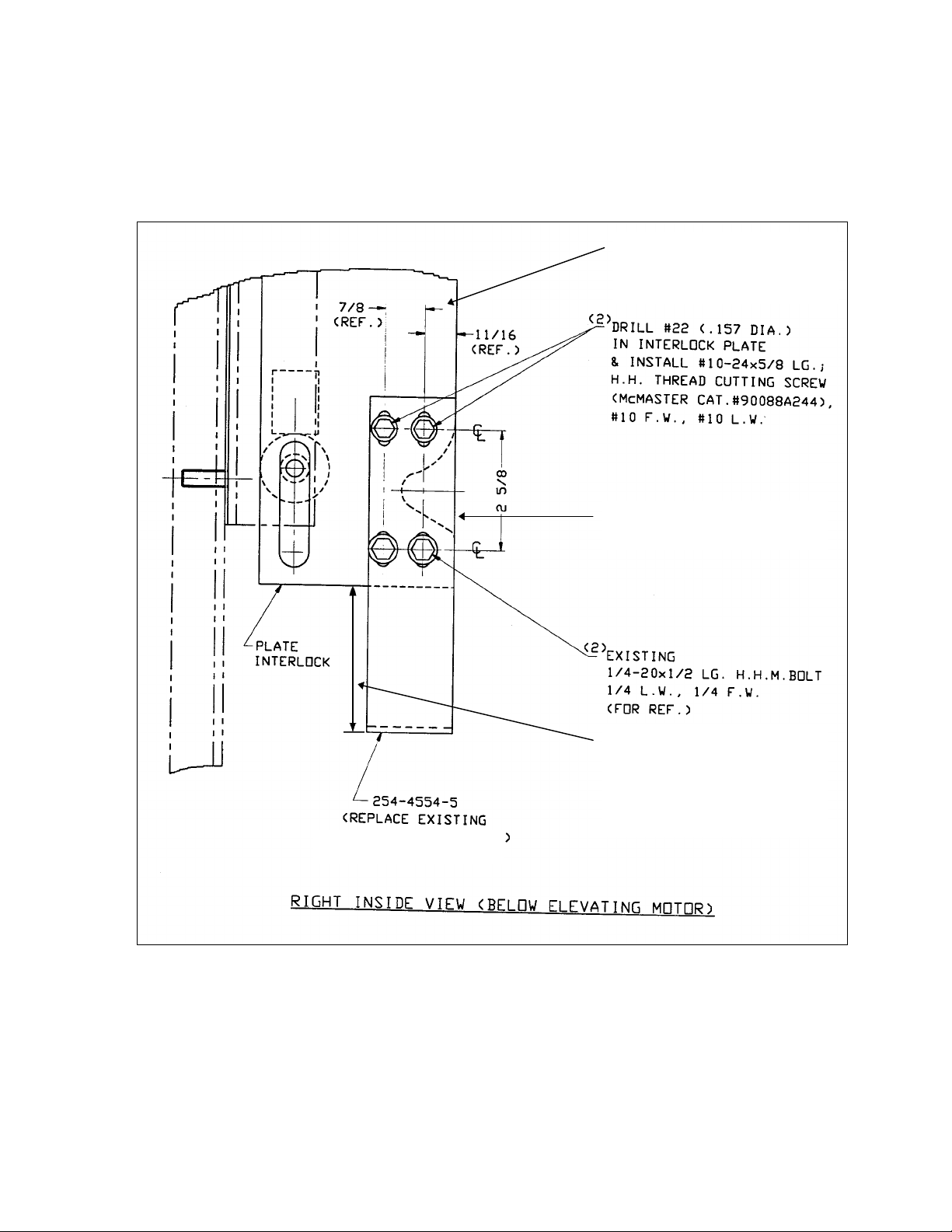
5. Drill two #22 (.157) diameter holes in the
positive interlock cam plate from locations in new
bracket supplied with kit. See Figure 2.
6. Install two #10-24 thread cutting screws
(supplied with kit).
7. Install the new clutch switch cover plate
supplied with the kit using the existing hardware.
8. All breaker cubicles that undergo this modi-
fication to the positive interlock cam plate must be
checked according to the dimensions given in
Figure 7.
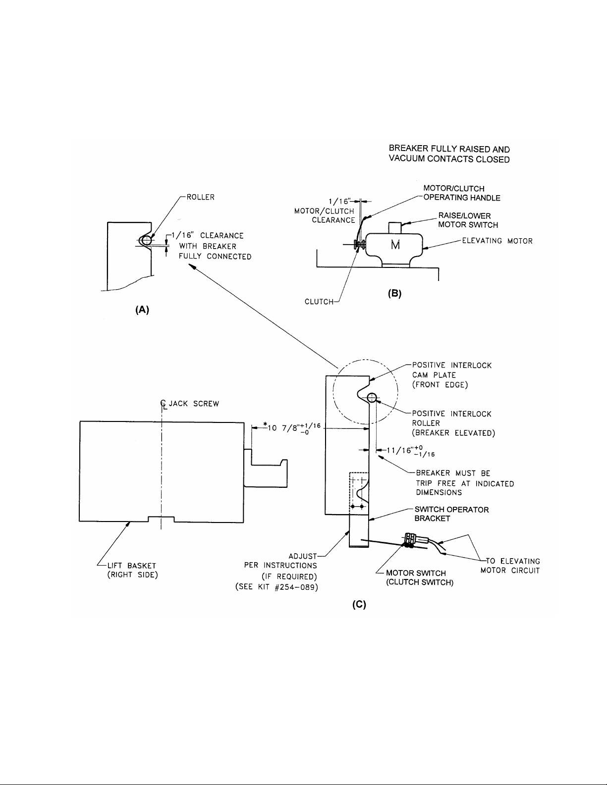
a. The 10-7/8” +1/16” -0” dimension from the
breaker to the front edge of the positive interlock
cam plate must be verified and maintained prior to
inserting a replacement PVVL vacuum breaker into
the cubicle. See Figure 7(C).
b. The 1/16” clearance between the stationary
flag, just behind the upper “Vee” notch and the
interlock roller must be maintained or reset if
required. The breaker should be in the fully raised
position. See Figure 7(A).
4.4 CHECKING FOR PROPER INTERLOCK
AND
TRIP FREE FUNCTIONS BEFORE LOWER-
ING THE BREAKER FROM THE ELEVATED
POSITION.
When the breaker is in the fully elevated and
connected position, releasing the motor operating
handle will return the positive interlock roller into
the upper notch in the interlock cam plate, closing
the interlock switches and energizing the circuit
that will charge the springs. The breaker may now
be closed.
In order to lower the breaker from the connected
position, the breaker must be open. If the breaker
is not open, the operator can not, and should not
be able to engage the clutch or activate the motor
circuit. The positive interlock roller will remain
locked and will not allow the interlock cam plate to
move vertically far enough to activate the
elevating motor.
To test the function of the positive interlock system
and trip free function, the following checks should
be made:
1. With the breaker closed and in the elevated
position, the positive interlock roller on the breaker
must remain locked and not allow the motor handle
to be moved far enough to engage the clutch and
close the clutch switch contacts that energize
the motor circuit. There should be 1/16” clearance
between the clutch and motor coupler, when the
motor handle is pulled forward. See Figure 7(A).
2. Disconnect the elevating motor plug from its
socket.
3. Trip the breaker to the open position.
4. Using the manual charging handle, charge the
closing springs in the breaker until the semaphore
shows “charged”.
5. Pull back the elevating handle on the motor so
that the interlock roller is at the dimension shown in
Figure 7. (11/16” +0 -1/16) Hold it in this position
while pressing the manual close push button on the
breaker. The main power springs must discharge
and the breaker must remain open, as indicated by
the semaphores on the front of the breaker. This
indicates that the breaker contacts will not close
during raising or lowering the breaker.
5. ADJUSTMENTS TO BREAKER/SWITCH-
GEAR INTERFACES.
The interfacing parts on all ratings of type AM
breakers and switchgear are functionally the same.
5.1 STATIONARY AUXILIARY SWITCH (MOC)
The Stationary Auxiliary Switch is an optional
switch mounted in the switchgear cubicle. When
the breaker has been elevated to the fully
connected position, the switach will be actuated
whenever the breaker is closed. The switch is
actuated by the plunger interlock (plunger)
mounted on the top of the breaker mechanism.
The switch has a number of “a” contacts (closed
when the breaker is closed and open when the
breaker is open) and “b” contacts (open when the
breaker is closed and closed when the breaker is
open). The following paragraph defines the
essential dimensions relating to the interfacing
elements of the breaker and switchgear, to assure
reliable performance.
The following elements are important factors which
commonly affect the operation of the stationary
auxiliary switch.
1. Plunger travel on the breaker.

GEH 6468A - Power/Vac VL Breaker Page 9
2. The gap between the top of the plunger on the
breaker and the bottom of the rod on the stationary
auxiliary switch mechanism.
3. Variations between breakers in the distance
from the underside of the lift rail and the top of the
plunger.
4. Variations in the rotation requirements to
“make” and “break” the stationary auxiliary switch
contacts.
5. Condition of the plunger interlock components
on the breaker.
6. Elevating mechanism limit switch consistency.
7. Breaker elevating mechanism positive stops.
8. Seismic events.
Some of these elements also affect the other
important interfaces required for reliable operation
of the equipment, such as:
1. Primary disconnect penetration.
2. Secondary coupler penetration.
3. The positive interlock mechanism.
A major goal in the design of switchgear has
always been the interchangeabililty of breakers.
GE Switchgear has been very successful in
achieving that goal for many years. Analysis of
instruction book adjustments, shop tolerances, and
service advice letters issued in recent years,
however, has demonstrated that tolerances in
switchgear equipment installed and presently
operating can result in situations where it is
impossible to meet all adjustments or that an
adjustment is brought into specification and it
causes a problem with another interface.
With specific reference to the plunger / stationary
auxiliary switch interface, the following instructions
and recommendations supersede all previous
Service Advice Letters and instructions. Refer to
Figure 1 for details.
Nominal breaker plunger travel is 1-1/8”. Nominal
auxiliary switch rod travel is 1-1/16”. It is
imperative that a gap is present between the top of
the plunger and the bottom of the rod, when the
breaker is in the fully connected position and the
breaker is open.
To assure the most reliable switch operation, it is
recommended that the plunger travel be measured
for each breaker and recorded in maintenance
records. It is further recommended that the
auxiliary switch mechanism be adjusted, if
necessary, to result in a gap that is in accordance
with the table given in Figure 10. It may require the
roll pin which
secures the auxiliary switch mechanism plate to be
removed and a new hole drilled after loosening the
two mounting bolts and moving the entire auxiliary
switch mechanism up or down.
This action may mean future adjusting when and if
different breakers are interchanged. Reliable
switch operation is critical and it may require
limiting your interchangeability of breakers. At a
minimum, the criticality requires adjustment
verification when swapping breakers.
Specifically, paragraph (f) on page 11 of Service
Advice Letter (S.A.L.) #073-323-1, dated 02-01-78
is rescinded and the instruction in GEH-1802X on
gap clearance is rescinded and both are replaced
with the gap dimension (“G”) given in the table of
Figure 10.
The plunger dimensions given in the breaker
instruction books are not rescinded because they
are correct nominal dimensions. It is permissible to
let the breaker adjustment be out of specification, if
it conflicts with the dimensions given in Figure 10.
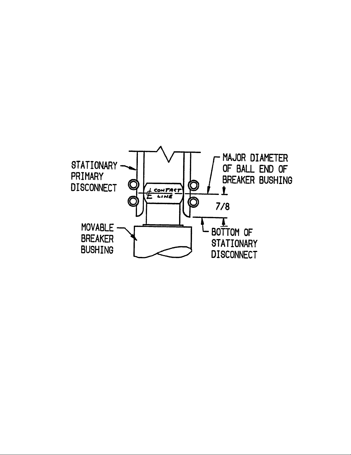
5.2 PRIMARY CONTACT PENETRATION
The nominal contact penetration is 7/8” as shown
in Figure 11. The tolerance on penetration is plus
5/32”, minus 1/8” on non 1E equipment and plus
1/16”, minus 1/8” on 1E equipment.
Reference Service Advice Letter # 073.323.1,
which addresses methods to check both the
penetration and the contact wipe for 5kV
equipment. The same methods and means of
adjustment also apply to 15kV equipment. GEH-
1802X and the similar illustrations it contains
showing proper contact wipe patterns should also
be consulted. It is essential to maintain proper
contact penetration while maintaining the
stationary auxiliary switch adjustment given in
Figure 10.
5.3 POSITIVE INTERLOCK
The purpose of the positive interlock it to prevent
moving the breaker to or from the connected
position while the main contacts are closed, and to
prevent closing the contacts unless the breaker is
in the fully connected position. These important
safety features are achieved by means of the
positive interlock roller on the right side of the
breaker and positive interlock cam and stationary
“flag” on the switchgear, as shown in Figure 7.

Page 10 GEH 6468A - Power/Vac VL Breaker
The following adjustments are made at the factory
and verified for proper operation per Figure 7. The
distance from the top of the stationary flag to the
top of the switchgear guide rails is set. This
maintains the surface upon which the breaker
wheels rest when the breaker is lowered. The
upper elevating motor limit switch is then adjusted
to achieve a roller to flag clearance of 1/16” to 1/8”
as shown in Figure 7. The limit switch de-energizes
the elevating motor circuit and should be activated
when the primary disconnects and secondary
coupler reach their nominal contact penetration
position. If the timing of this sequence is off, the
cubicle must be adjusted back to factory
specifications.
Instructions for positive interlock adjustment are
detailed on Figures 13, (1000 MVA Equipment),
Figure 14, (M-26 Equipment); and Figure 15, (M-36
Equipment). These adjustments are also detailed
in instruction book GEH-1802X.
5.4 SECONDARY COUPLER
On the top front of the breaker, there is a black
plastic block which holds male secondary coupler
pins. This block should make contact with, and
slightly raise a spring loaded black plastic block
which holds female secondary coupler sockets on
the switchgear. The contact depression should be
1/8”. The stationary block is adjustable in the
vertical direction as described in Service Advice
Letter 073-323-1. It is not always possible to have
the black plastic blocks in contact over their entire
flat surface. Often, the rear of the blocks are
engaged while a gap exists along the front edge.
This is an acceptable condition. The contacting
block surfaces should touch and the female block
edge move upward between 1/32” to 1/8”.
5.5 SPRING DISCHARGE CAM
The purpose of the spring discharge interlock is to
discharge all stored energy in the breaker
mechanism whenever the breaker is withdrawn
from the cubicle. The discharge interlock is located
on the left side of the breaker. The spring
discharge cam mounted in the switchgear should
discharge the breaker closing spring when the
breaker is lowered.
The cam has minimal adjustment provision. The
holes may be slightly slotted to adjust the cam
vertically to allow discharge when the breaker
wheels reach 1/8” to ¼” height above the floor.
Refer to GE drawing 0184B7344 for instructions on
installing a spring discharge cam in the switchgear
cubicle.
5.6 STOPS
The stop pins and stop bolts on the elevating
mechanism are emergency mechanical stops
which would come into use only if the upper
elevating motor switch is completely out of
adjustment or has failed. Elevating against these
stops may be quite audible and the operator should
release the clutch handle, de-energizing the
elevating motor circuit or, the elevating motor
circuit protective fuse will open to protect the
motor. The stop bolts should be set to 3/32 to 1/8”
clearance and only set after all other elevating
adjustments are made.
5.7 GROUND
A visual check should be made to observe the
ground connection. The ground shoe on the
moveable breaker is designed to have a nominal
engagement of 1-½” + ¼” vertically with the steel
and copper spring loaded disconnects of the
ground device in the switchgear.
5.8 POSITION SWITCH (TOC)
The position switch is an optional device mounted
in the rear left side of the switchgear cubicle. The
switch contacts operate when the lifting
mechanism is in either the fully raised or fully
lowered position. Switch operation should be
checked with the breaker withdrawn manually and
the equipment de-energized, and again electrically,
with the breaker in the cubicle. Refer to Service
Advise Letter 073-326.1, dated 5-23-78 for a
description of design changes made to improve the
switch operating mechanism in 1978.
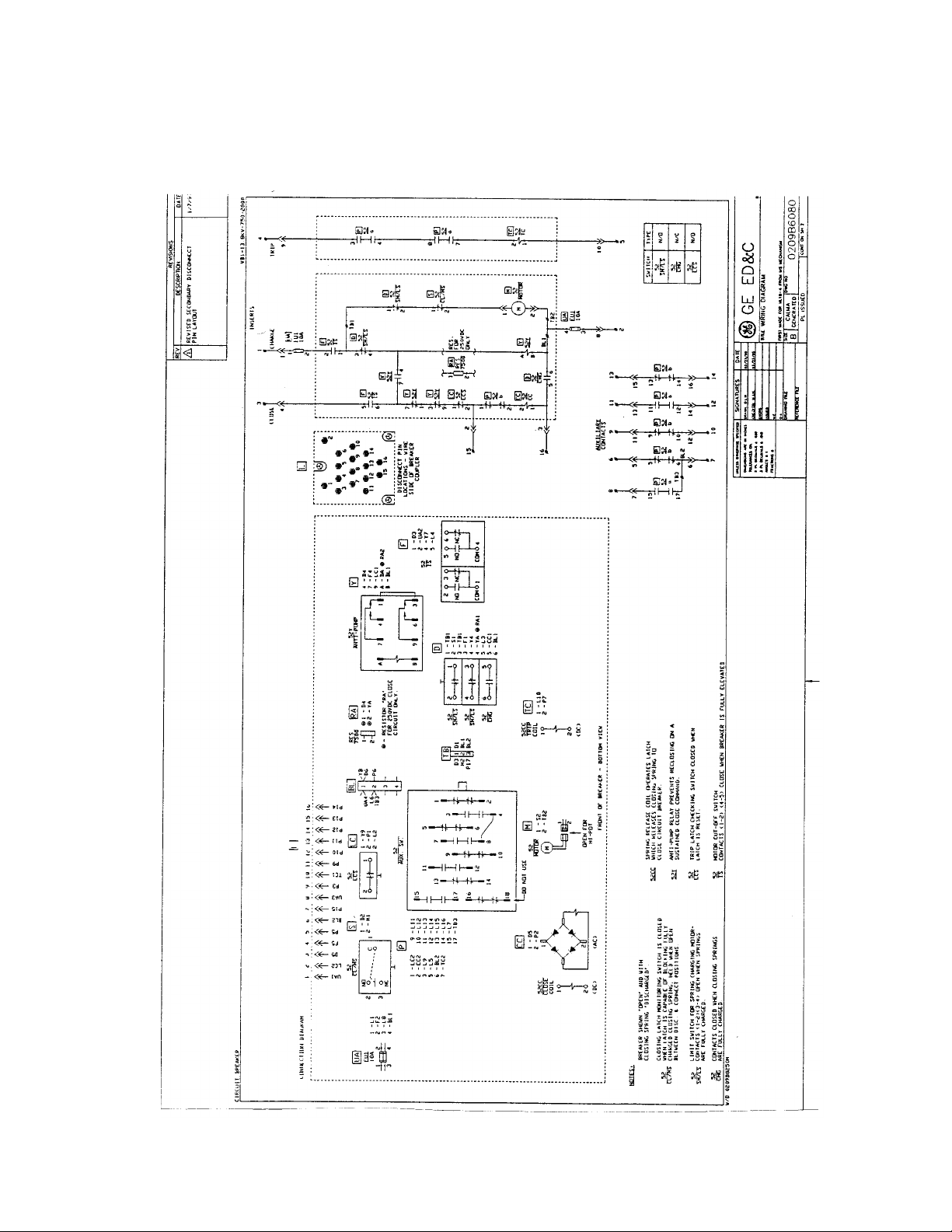
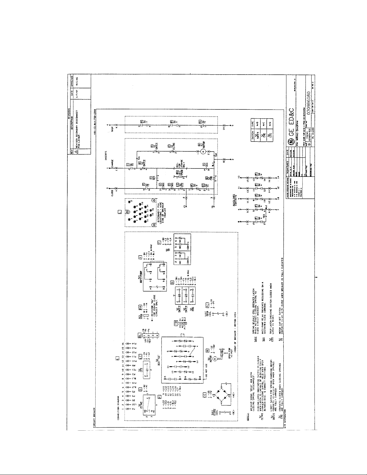
6. TYPICAL WIRING DIAGRAMS

GEH 6468A - Power/Vac VL Breaker Page 11
Figures 8 and 9 show typical wiring diagrams for
PowerVac
®
VL breakers.
Replacement breakers for old units with solenoid
mechanisms (AM breakers with MS type mech-
anisms) are typically wired per the drawing in
Figure 8.
Replacement breakers for old units with stored
energy mechanisms (AM breakers with ML type
mechanisms). are typically wired per the drawing in
Figure 9.
The wiring on your breakers may be different.
Consult your nameplate for the correct drawing
number and call your local GE office for additional
copies of this drawing are required.
Page 12 GEH 6468A - Power/Vac VL Breaker
FIGURE 1
INTERIOR VIEW OF STATIONARY CUBICLE
Stationary
Aux Switch
SB Control
Switch
Grill
Cutout
Front Door
Edge Protector
Wire Grill
GEH 6468A - Power/Vac VL Breaker Page 13
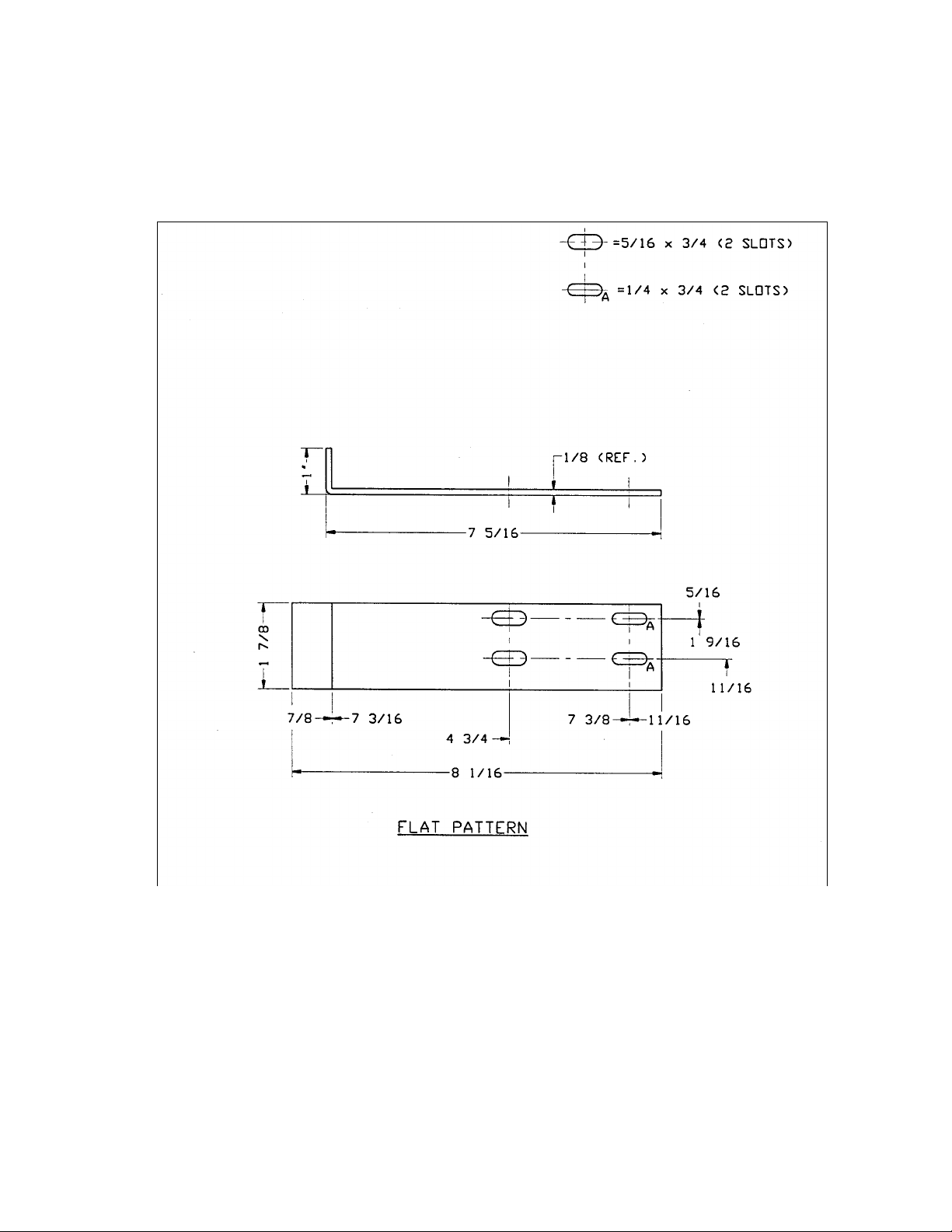
FIGURE 2
INTERLOCK MODIFICATION
Positive Interlock Cam Plate
Record this dimension before
removing old switch operator
bracket.
New bracket should be adjusted
to this dimension.
SWITCH OPERATOR BRACKET
New Switch Operator Bracket
(Shown Blocking Lower Notch)
Page 14 GEH 6468A - Power/Vac VL Breaker
FIGURE 3
MOTOR OPERATOR SWITCH ACTUATOR
GEH 6468A - Power/Vac VL Breaker Page 15
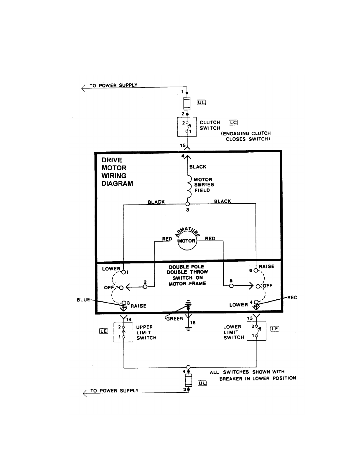
FIGURE 4
ELEVATING MOTOR TROUBLESHOOTING
TROUBLE SHOOTING
IF ELEVATING MOTOR DOES NOT OPERATE:
CORRECTIONS
1. Check power supply
2. Check fuses UL
3. Check and adjust mechanical clutch linkage to clutch switch LC
4. Check LC for proper performance
5. Check motor switch
6. Check motor
7. Adjust upper LE and lower LF limit switches for proper breaker position
8. Check and adjust leaf springs to provide proper tilt to operate limit switches
9. Check plug and receptacle for proper connections
10. Check clutch and mechanism
Page 16 GEH 6468A - Power/Vac VL Breaker
FIGURE 5
SCHEMATIC DIAGRAM
VERTICAL LIFT ELEVATING MECHANISM
DO NOT USE RAISE/LOWER SWITCH TO STOP & START MOTOR.
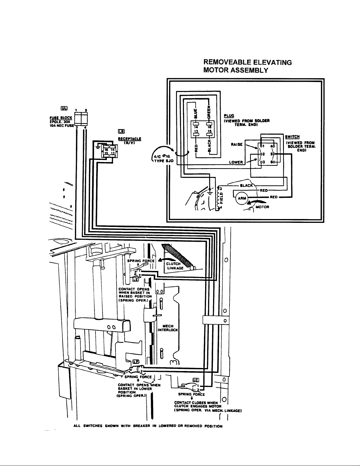
GEH 6468A - Power/Vac VL Breaker Page 17
FIGURE 6
STATIONARY STRUCTURE WIRING
Page 18 GEH 6468A - Power/Vac VL Breaker
FIGURE 7
BY-PASS KIT INSTALLATION
GEH 6468A - Power/Vac VL Breaker Page 19
FIGURE 8
TYPICAL BREAKER WIRING DIAGRAM
(REPLACEMENT FOR BREAKERS WITH MS MECHANISMS)
Page 20 GEH 6468A - Power/Vac VL Breaker
FIGURE 9
TYPICAL BREAKER WIRING DIAGRAM
(REPLACEMENT FOR BREAKERS WITH ML MECHANISMS)

GEH 6468A - Power/Vac VL Breaker Page 21
FIGURE 10
ADJUSTMENT OF PLUNGER INTERLOCK
Adjustment of plunger interlock - Breaker raised to connect position. Gap adjustment as a function
of breaker plunger travel to assure proper switch operation.
P G R
Plunger
Interlock
Travel
Gap between top of plunger interlock and
bottom of aux. switch rod
Resulting travel of the aux. switch rod
(To be
measured) Min. Max. Min. Max.
1-1/16 .001 1/16 1” 1-1/16
Page 22 GEH 6468A - Power/Vac VL Breaker
FIGURE 11
PRIMARY CONTACT PENETRATION
 Loading...