


AF-300E$ TM
1/2 - 350 Horsepower
Instructions

General Information – AF-300E$™ Instructions
These instructions do not purport to cover all details or variations in equipment, nor to provide for every possible contingency to be met during installation, operation, and maintenance. Should further information be desired or should particular problems arise that are not covered sufficiently for the purchaser's purpose, the matter should be referred to GE Fuji, Technical Service.
NOTE: The terms "inverter", "controller", and "drive" are sometimes used interchangably throughout the industry. We will use the term "Drive" in this document.
AF-300E$™ and X$D™ are trademarks of the General Electric Company.
Energy $aver® is a registered trademark of the General Electric Company.
NOTE: Always read the complete instructions prior to applying power or troubleshooting the equipment and follow all procedures step by step.
SHOCK HAZARD labels may be located on or inside the Drive to alert people that dangerous voltage may be present.
WARNING, CAUTION AND NOTES
The following format is used on the equipment or found in this manual. Read all labels and follow the directions on them whenever working on the equipment.
WARNING: Denotes operating procedures and practices that may result in personal injury or loss of life if not correctly followed.
CAUTION: Denotes operating procedures and practices that, if not strictly observed, may result in damage to, or destruction of the equipment.
NOTE: Notes call attention to information that is especially significant in understanding and operating the equipment.
WARNING, CAUTION AND NOTE PARAGRAPHS WITHIN THIS INSTRUCTION
The above paragraphs list some general safety reminders and safety recommendations to be followed when operating or installing this equipment. These safety precautions will be repeated throughout this instruction book where applicable.
Copyright © 1998 by General Electric Company, USA.
i
Table of Contents
1. SAFETY PRECAUTIONS .......................................................... |
1-1 |
2. DESCRIPTION, COMPONENT IDENTIFICATION, |
|
AND SPECIFICATIONS ................................................................ |
2-1 |
General Description ......................................................................... |
2-1 |
Upon Delivery Inspection Procedures .............................................. |
2-2 |
Drive Keypad Functions and Layout ................................................ |
2-3 |
Table 1: AF-300E$ - Standard Specifications .................................. |
2-3 |
Model Numbering System Diagram ................................................. |
2-7 |
Table 2: AF-300E$ - Drive Dimensions ............................................ |
2-8 |
CE Labeled Products ...................................................................... |
2-9 |
Table 3: AF-300E$ - Drive Ratings, Efficiencies and Watts Loss .... |
2-10 |
3. INSTALLATION GUIDELINES .................................................. |
3-1 |
Installation Environment ................................................................... |
3-1 |
Installation Mounting Clearance ....................................................... |
3-2 |
AF-300E$ Dimension Drawings ....................................................... |
3-3 |
4. WIRING PROCEDURES ........................................................... |
4-1 |
Remove Terminal Block Cover ......................................................... |
4-1 |
Control Circuit Wiring ...................................................................... |
4-2 |
Main Circuit Wiring .......................................................................... |
4-3 |
Table 4: AF-300E$ - Drive Cable Size Recommendations and Circuit |
|
Protection Rating ............................................................................ |
4-4 |
Figure 4-5: AF-300E$ - 1/2 to 30 Hp Connection Diagram ............. |
4-7 |
Figure 4-6: AF-300E$ - 40 to 300 Hp Connection Diagram ............ |
4-8 |
Table 5: AF-300E$ - Terminal Identification/Function ....................... |
4-9 |
Auxiliary Control Power Supply Connection ................................... |
4-11 |
DC Link Reactor Connection ......................................................... |
4-12 |
Automatic Restart Circuit Connection ............................................ |
4-14 |
Drive Interface Details .................................................................... |
4-15 |
Main Circuit Wiring for CE Mark .................................................... |
4-16 |
Dynamic Braking Technical Information ......................................... |
4-17 |
5. INVERTER OPERATION ........................................................... |
5-1 |
Pre-Operation Inspection ................................................................ |
5-1 |
Keypad Panel Identification/Operation ............................................. |
5-1 |
Function Code and Data Code Description/Selection ...................... |
5-1 |
Keypad and Display Operation Programming .................................. |
5-2 |
Program Mode - Example of Changing a Function Code ................. |
5-3 |
Program Mode - Example of Checking Function Codes .................. |
5-4 |
Program Mode - Checking Input/Output Signals ............................. |
5-5 |
Keypad Fault Indication ................................................................... |
5-6 |
Display at a Fault ............................................................................. |
5-8 |
Accessing Fault History ................................................................... |
5-9 |
Table 7: Function Code Settings .................................................... |
5-10 |
`6. FUNCTION CODE DESCRIPTIONS ........................................ |
6-1 |
Basic Function ................................................................................ |
6-1 |
Input Terminal Functions ............................................................... |
6-13 |
ACCEL/DECEL Times ................................................................... |
6-15 |
|
Motor #2 ....................................................................................... |
6-16 |
|
Analog Monitor Output .................................................................. |
6-17 |
|
Output Terminals ........................................................................... |
6-18 |
|
Output Terminal Functions ............................................................. |
6-20 |
|
Frequency Control ......................................................................... |
6-22 |
|
LED & LCD Monitor ....................................................................... |
6-24 |
|
Pattern Operation .......................................................................... |
6-26 |
|
Special Functions .......................................................................... |
6-31 |
|
Motor Characteristics .................................................................... |
6-33 |
|
Special Functions (Data Protection) ............................................... |
6-34 |
|
7. MAINTENANCE AND INSPECTION ........................................ |
7-1 |
|
Megger Test .................................................................................... |
7-1 |
|
Periodic Parts Replacement ............................................................ |
7-1 |
|
Inspection Items .............................................................................. |
7-1 |
|
Measurement Points and Meters ..................................................... |
7-2 |
|
8.TROUBLESHOOTING................................................................ |
8-1 |
|
Fault Condition Description and Operation ...................................... |
8-1 |
|
Fault Condition Display and Corrective Actions ............................... |
8-2 |
|
(1) |
Overcurrent ................................................................................ |
8-9 |
(2) |
Ground Fault .............................................................................. |
8-9 |
(3) |
Overvoltage .............................................................................. |
8-10 |
(4) |
Undervoltage ............................................................................ |
8-11 |
(5) |
Inverter Overheat ...................................................................... |
8-12 |
(6) |
External Failure ......................................................................... |
8-12 |
(7) |
Overload .................................................................................. |
8-13 |
(8) |
DC Link Fuse Blown ................................................................. |
8-13 |
(9) |
Memory Error, Keypad Communication, CPU Error .................. |
8-14 |
(10) Timing Error ........................................................................... |
8-14 |
|
(11) Motor Will Not Run ................................................................. |
8-15 |
|
(12) Motor Will Run But Speed Will Not Change ............................ |
8-16 |
|
(13) Motor Will Stall During Acceleration ........................................ |
8-17 |
|
(14) Motor Heating Abnormal ........................................................ |
8-17 |
|
Control Block Diagram .................................................................. |
8-18 |
|
9. WARRANTY PARTS AND SERVICE ........................................ |
9-1 |
|
Warranty Coverage ......................................................................... |
9-1 |
|
Out-Of-Warranty Procedures ........................................................... |
9-1 |
|
Motors ............................................................................................ |
9-1 |
|
In Warranty Failure Check List |
|
|
(Data necessary for Warranty Administration) .................................. |
9-2 |
|
10. REPLACEMENT PARTS ....................................................... |
10-1 |
|
11. GLOSSARY - DRIVES TERMINOLOGY ............................... |
11-1 |
|
12. ELECTROMAGNETIC COMPATIBILITY .............................. |
12-1 |
|
(1) |
General .................................................................................... |
12-1 |
(2) |
RFI Filters ................................................................................. |
12-2 |
(3) |
Recommened Installation Instructions ...................................... |
12-3 |
ii
Section 1: Safety Precautions
WARNING - MECHANICAL MOTION HAZARD:
Drive systems cause mechanical motion. It is the responsibility of the user to insure that any such motion does not result in an unsafe condition. Factory provided interlocks and operating limits should not be bypassed or modified.
WARNING - ELECTRICAL SHOCK AND BURN HAZARD:
When using instruments such as oscilloscopes to work on live equipment, the oscilloscope’s chassis should be grounded and a differential amplifier input should be used. Care should be used in the selection of probes and leads and in the adjustment of the oscilloscope so that accurate readings may be made. See instrument manufacturer’s instruction book for proper operation and adjustments to the instrument.
WARNING - FIRE AND EXPLOSION HAZARD:
Fires or explosions might result from mounting drives in hazardous areas such as locations where flammable or combustible vapors or dusts are present. Drives should be installed away from hazardous areas, even if used with motors suitable for use in these locations.
WARNING - STRAIN HAZARD:
Improper lifting practices can cause serious or fatal injury. Lift only with adequate equipment and trained personnel.
WARNING - ELECTRICAL SHOCK HAZARD:
All motor bases and equipment enclosure housings should be grounded in accordance with the National Electric Code or equivalent.
WARNING - MOTOR OVERSPEED HAZARD:
With 400 Hz drive output possible, the drive will allow the motor to run up to 6 - 7 times its base speed. Never operate the motor above its top mechanical speed or a catastrophic failure may occur.
Any applications requiring operation above
120 Hz must be approved by the Company.
WARNING -
Before disassembling, disconnect and lock out power from the drive. Failure to disconnect power may result in death or serious injury. A bus charge light provides visual indication that bus voltage is present; verify the bus voltage level by measuring the voltage between power terminals P(+) and N(-) using an analog meter. Do not attempt to service the drive until the charge indicator has extinguished and the bus voltage has discharged to zero volts.
WARNING -
Replace all covers before applying power to the drive. Failure to do so may result in death or serious injury.
CAUTION:
Do not connect power supply voltage that exceeds the standard specification voltage fluctuation permissible. If excessive voltage is applied to the drive, damage to the internal components will result.
CAUTION:
Do not connect power supply to the output terminals (U, V, W). Connect power supply only to the power terminals (L1, L2, L3).
CAUTION:
Even though the main AF-300E$ power has been disconnected it may still receive electrical energy from more than one source. If external power is applied to the control terminals 30A, B & C and AX1 and AX2 as well as any option card control input terminal points (if installed in the drive), and if the independent power source is activated separately from the AF-300E$'s main input power, failure to to diconnect this external power source may result in death or serious injury. This external power must be removed prior to any work being performed on the drive.
WARNING: this equipment may receive electrical energy from more than one source. Additional disconnects are located outside this cabinet. Open all associated disconnects before servicing equipment. Refer to equipment diagrams.
1-1
CAUTION:
For RUN and STOP, use the FWD-CM (forward) and REVCM (reverse) terminals. Do not use a contactor (ON/OFF) installed on the line side of the drive for RUN and STOP.
CAUTION:
Do not use a switch on the output side of the drive for ON/ OFF operation.
CAUTION: Do not connect filter capacitors on the output side of the drive.
CAUTION:
Do not operate the drive without the ground wire connected. The motor chassis should be grounded to earth through a ground lead separate from all other equipment ground leads to prevent noise coupling.
The grounding connector shall be sized in accordance with the NEC or Canadian Electrical Code. The connection shall be made by a UL listed or CSA certified closed-loop terminal connector sized for the wire gauge involved. The connector is to be fixed using the crimp tool specified by the connector manufacturer.
CAUTION:
Do not perform a megger test between the drive terminals or on the control circuit terminals.
CAUTION:
The AF-300E$ drive develops an adjustable frequency via pulse width modulation, with the pulse rise time of 0.1 microseconds. While this does not present a problem on 200-230Vac applications, it may on 380-460Vac applications. When using the AF-300E$ drives on 380-460Vac, where the distance between the motor and the drive exceeds 60 feet, get the motor manufacturer's approval that his insulation system can withstand the voltage spikes (up to twice the dc bus voltage 2 x 621Vdc for a 460Vac power source) of the drive, in conjunction with the long motor cable lengths. If the insulation system does not meet this limit, utilize a filter to increase the Drive's pulse rise time to 1.0 microseconds.
CAUTION:
Because the ambient temperature greatly affects drive life and reliability, do not install the drive in any location that exceeds the allowable temperature. Leave the ventilation cover attached for temperatures of 40 degrees C or below, and remove the cover for temperatures of between 40 (104° F) and 50 (122° F) degrees C (30 Hp and lower).
If the cover needs to be removed, another type of enclosure may be required for safety purposes.
CAUTION:
If the Drive’s Fault Alarm is activated, consult the TROUBLESHOOTING section of this instruction book, and after correcting the problem, resume operation. Do not reset the alarm automatically by external sequence, etc.
CAUTION:
Be sure to remove the desicant dryer packet(s) when unpacking the drive. (If not removed these packets may become lodged in the fan or air passages and cause the drive to overheat.)
CAUTION:
AC induction motors require that they be sized based on the applications speed range and associated torque requirements for the motor-drive system. This is to avoid excessive motor heating. Observe motor manufacturers recommendations when operating any ac induction motor with the drive. Also observe motor manufacturer's recommended voltage/torque boost at lower operating frequencies.
CAUTION:
The available power source connected to the drive is not to exceed 500KVA. If the ac power source is greater than 500KVA and the driver's rating (Hp) is less than 10% of the power source's KVA; ac line reactors will have to be installed in L1, L2 & L3 power leads of the drive.
CAUTION:
The drive must be mounted on a wall that is constructed of heat resistant material. While the drive is operating, the temperature of the drive's cooling fins can rise to a temperature of 90°C (194°F.)
1-2

Section 2: Description, Component Identication and Specifications
The AF-300E$ drive is available in ratings of 0.5 to 30 Hp 200-230 VAC, 1 to 300 Hp (350Hp variable torque) 380-460 VAC. The AF-300E$ drive incorporates multiple control algorithms with either the traditional PWM Scalar power control or a selectable torque vector algorithm with a self tuning drive/motor function that is used in high performance operation. The AF-300E$ Drives are housed in a NEMA 1 type enclosure for either open or panel mounting and all Inverters are furnished with a detachable wiring lead-in plate to allow ease of accessing control and power wiring.
Drive operation and Function Code setting is performed from the “Keypad Panel” that also features a Digital Monitor, LCD Graphic Display and 8 dual function keys. The 8 dual function keys are used for drive programming and operation as well as selection of drive local/remote operation.
General data and specification for each drive are listed on the nameplate attached to the drive. Refer to TABLE 1 for complete AF-300E$ drive specification listing.
INSPECTION PROCEDURES UPON DELIVERY
Upon receipt of your drive, inspect the equipment for the following items:
1.Check the nameplate to insure that the specifications correspond to those ordered.
2.Inspect the unit for any damage that may have occurred during shipment.
If shipping damage is found or the wrong Inverter is received, contact the distributor from which this equipment was purchased.
|
|
|
AF-300E$ TM |
||
|
|
|
|
|
|
MODEL NO. |
|
|
|
|
|
SERIAL NO. |
|
CONSTANT |
VARIABLE |
||
INPUT: |
|
||||
|
|||||
|
TQ OUTPUT: |
TQ OUTPUT: |
|||
VOLTS |
|
||||
AMPS |
|
|
VOLTS |
||
|
FREQ RANGE (HZ) |
||||
FREQ (HZ) |
|
||||
|
|
HP |
|||
PHASE (S) |
|
|
|||
|
AMPS CONT. |
||||
|
|
||||
|
|
|
PHASE |
||
|
|
|
ROTATION |
||
INSTRUCTION |
|
MAX 60 SEC. AMPS |
|||
BOOK GEI-100211 |
|
GE Fuji Drives America |
Made in Mexico |
||
|
|||||
|
|
|
|
|
|
All models are UL Listed and CSA Approved* (Nameplate shown larger than actual size.)
Figure 2-1. NAMEPLATE DATA IDENTIFICATION
* CE Mark for three-phase (3ø), 415 VAC, 1 to 30 Hp only.
2-1

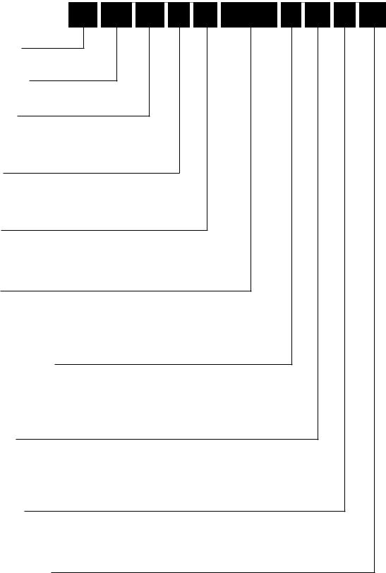
Drive Keypad Functions and Layout
Indication of keypad panel operation |
|
Digital Monitor (4-digit) |
} Unit displayed |
|
LCD Graphic Display
|
|
|
|
|
|
|
Up - Down Keys |
|
|
|
|
|
|
|
|
Run Light |
|
|
|
|
|
|
|
|
||
Program Key |
|
|
|
|
Run Key |
|||
|
||||||||
Shift Key |
|
|
|
|
|
|
Function/Data Key |
|
|
|
|||||||
Reset Key |
|
|
|
|
|
|
Stop Key |
|
|
|
|
|
|
|
|||
|
|
|
|
|
|
|
|
|
Figure 2-2. KEYPAD PANEL COMPONENT IDENTIFICATION
Attachment Screws -The Keypad Panel can be easily removed from the Drive unit by loosening the two attachment screws. With the optional extension cable, remote Keypad operation and display is possible.
LCD Graphic Display - LCD Display shows control status or Function Code settings.
PROGRAM (PRG) Key - Operation Mode or Program Mode selection key.
SHIFT (>>) Key - Changes the digital monitor display in the Operation Mode. Will also change the LCD graphic display in Program Mode and Trip Mode.
SET FUND/DATA Key - Displays data setting of selected Function Codes. Also, stores any changes in software.
RESET Key - After removal of the fault condition, faults can be reset and will return the Drive to the Operation Mode.
Remote/Local Operation - Remote/Local operation can be toggled by pressing the RESET and STOP keys simultaneously when the Drive is stopped.
RUN Key - This key is the RUN command in Keypad operation, run light will be illuminated at this time.
STOP Key - This key is used for stopping operation. If pressed when the Drive is running by external control, fault Er6 will be displayed and Drive will coast to a stop.
UP - DOWN Keys - These keys increase or decrease the frequency (or speed) of the Drive. When unit is in Program Setting Mode, they change the Function Code or Data Code values.
LCD Brightness - Function Code 79 permits adjustment for easy to read brightness of the graphic display.
Unit Display - The unit information is displayed by LEDs during RUN or STOP condition.
Digital Monitor - Displays Hz, Volts, R/Min, M/Min, or % as set by the operator using the SHIFT (>>) key or resetting Function Code 61.
2-2

Table 1: AF-300E$ – Standard Specifications
Environmental Conditions
Enclosures |
NEMA 1 Standard |
|
|
Installation Location |
Suitable for indoor mounting only, less than 1000 meters (3300 feet) elevation, not in |
|
contact with corrosive gas, oil mist, dust, and out of direct sunlight. |
|
|
Stored Temperature |
-20° to +65°C (-4° to + 149°F) |
|
|
Ambient Temperature |
-10 to +50oC (+14 to +122oF) (remove ventilation covers if temperature is over +40oC |
|
[+104oF] up to 30 Hp; 40 Hp and above not required.) |
|
|
Humidity |
20% to 90% relative humidity (non-condensing). |
|
|
Vibration |
0.6G or less. |
|
|
Cooling Method |
1/2 to 1 Hp – Convection |
|
|
|
2 Hp and greater – Forced air |
|
|
Output |
|
|
|
Rated Output Voltage |
3-Phase, 3-Wire Type, 80-240 VAC or 320-480 VAC |
|
(Can not exceed power supply voltage). |
|
|
Frequency Range |
0 - 400 Hertz (0.2 to 60 Hz start frequency; 0.2 to 120 Hz base frequency). |
|
Above 120 Hz, contact Company for approval of application. |
|
|
Overload Current Rating |
– 30 Hp and lower |
|
150% for 1 minute duration (inverse time characteristic) |
|
200% for 0.5 seconds |
|
– 40 Hp and greater |
|
150% for 1 minute duration (inverse time characteristic) 180% for 0.5 seconds |
|
|
Power Supply |
|
|
|
Rated Input AC Voltage |
– 200 to 230 VAC 50/60 Hz, 3 phase (1/2 to 30 Hp) |
|
– 380 to 400 VAC 50 Hz, 3 phase (1 to 300 Hp) CT |
|
– 380 to 480 VAC 60 Hz, 3 phase (1 to 300 Hp) CT |
|
– 460-480 VAC, 60 Hz, 3 phase, 40 Hp and above, variable torque applications only |
|
Voltage - +10%, -15%; Voltage Unbalance - Within 3%; Frequency - +/-5% Units are |
|
dual rated Constant Torque/Variable Torque. Drive looks for a similar Volts/Hz ratio). |
|
|
Control System |
Sinusoidal PWM Control (or with torque-vector control.) |
|
|
Momentary Voltage Dip |
When the input voltage dips below 165 VAC (230V System), 310 VAC (460V system) or |
|
400 VAC (575V System), the Drive can operate for 15 ms with 85% full load applied. |
|
|
Starting Torque |
150% (when torque vector control is active.) |
|
|
Carrier Frequency |
– 2 to 15 KHz (1/2 to 30 Hp) 230 & 460 VAC |
|
– 2 to 10 KHz (40 to 75 Hp) – 2 to 6 KHz (100 Hp and greater) |
|
|
2-3

Frequency Setting Resolution |
– Analog: 1⁄3000 of max. frequency (0.02 Hz/60 Hz; 0.04 Hz/120 Hz) |
|
– Digital: 0.01 Hz (max. frequency up to 99.99 Hz); |
|
0.1 Hz (max frequency of 100 Hz or more) |
|
|
Accuracy (Stability) |
– Analog setting: ± 0.2% of max. frequency (@ 25 ± 10°C) |
|
– Digital setting: ± 0.01% of max. frequency (@ -10 to + 50°C) |
|
|
Voltage/Frequency |
Voltage - 80-240 VAC, 320-480 VAC |
Characteristics (V/F) |
Frequency - 0.2 to 400 Hz |
|
|
Torque Boost |
– Auto: Automatic torque boost control by torque calculated value. |
|
– Manual: 0.0 to 20.0 code setting (includes the energy savings pattern, |
|
Function Code for variable torque load.) |
|
|
Acceleration/Deceleration |
0.2 to 3600 seconds (independent acceleration/deceleration) |
Characteristics |
4 selectable linear and non-linear "S" curve characteristic. |
|
|
Internal Functions: |
The quality of the sound produced by the motor can be changed to |
Operating Sound Selection |
reduce irritating noise. |
|
|
Frequency Meter Adjustment |
Scale calibration of externally connected analog meter (6.5-10.5 VDC) or pulse frequency |
|
6 to 100 times output frequency. |
|
|
Data Protection |
Data lock is possible to ensure that the data codes are not changed. |
|
|
Pattern Operation |
Seven independent stages (frequency up to 400 Hz, duration up to 6,000 seconds each. |
|
Configuration: |
|
Single cycle |
|
Repeat cycling |
|
Single cycle with continuous 7th speed |
|
|
Momentary Power |
Five selections available. (Refer to Power Supply Specification.) |
Loss Ride Thru |
|
|
|
High/Low Limiter |
Output frequency upper and lower range limit 0 to 400 Hz; 1 Hz step settings. |
|
|
Bias |
Magnitude of the zero offset can be set from 0 to 100% of maximum |
|
frequency (1 Hz steps.) |
|
|
Gain |
Output frequency gain corresponding to the reference signal can be set |
|
from 0 to 200% (0.1% steps.) |
|
|
Programmable Jump Frequency |
Three selectable frequencies can be set to avoid a mechanical resonant point. Width is |
|
adjustable from 0 to 30 Hz (1 Hz steps.) |
|
|
Slip Compensation Control |
Maintains motor at constant speed with load fluctuations. |
|
Adjustable from -9.9 Hz to +5.0 Hz. |
|
|
Torque Limit Control |
Output torque can be controlled within a range of 20% to 180% (1% steps.) |
|
|
7 Step Preset Speed |
7 programmable preset speeds selectable by 3 contact closures. |
|
|
Momentary or Maintained |
Selection between the maintained contact operation/stop command (2-wire operation) or |
Contact Operation |
the momentary contact (3-wire operation). |
|
|
Terminal Function Change |
Multi-Use terminals changed via Function Code settings. |
|
X1 to X5 inputs; Y1 to Y5 outputs. |
|
|
Line to Drive Transition Logic |
Motor transfer function from the AC line to Drive operation. |
|
|
Sensorless Vector Control |
– Improves torque characteristics throughout speed range. |
|
– Improves speed regulation. |
|
|
2-4

Operation
Frequency Reference Signal |
– Speed potentiometer/0 to +10 VDC |
|
|
– 4 to 20 mA |
|
|
– 0 to ±10 VDC (Standard on 40 Hp and greater) (Option on 1/2 to 30 Hp) |
|
|
|
|
Input Signal (contact type) |
Forward, reverse, self-holding selection (when operation is 3-wire), multi-step |
|
|
speed setting (7-step), multiple accel/decel time settings (4 settings), |
|
|
coast-to-stop, external alarm, and reset. |
|
|
|
|
External Output Signals |
One Dry Form "C" alarm output contact rated 250 VAC, 0.3 amp.one auxiliary run |
|
|
contact rated 250 VAC, 0.3 amp (available only on 40 Hp and above ratings.) |
|
|
5 – Open collector outputs each rated 24 VDC, 50mA from external power. |
|
|
– Drive Run |
– Time-up signal during pattern mode |
|
– Frequency equivalence signal |
– Undervoltage detection |
|
– Overload early warning |
– Keypad operation |
|
– Auto restart mode |
– Torque limiting mode |
|
– Cycle completion pattern mode |
– Auto reset mode |
|
|
|
Protective Functions: |
– Stall prevention |
– Undervoltage |
|
– Momentary power failure |
– Overcurrent |
|
– Drive overheating |
– Overvoltage |
|
– External faults |
– Link error |
|
– CPU malfunction |
– Communication error |
|
– Motor overload |
– Ground fault |
|
(electronic thermal) |
|
|
|
|
Frequency Meter Output Signal |
Pulse frequency (6 to 100) times output frequency. |
|
|
Analog - 0 to +10 VDC (adjustment range of 6.5 to 10.3 VDC) |
|
|
|
|
Keypad |
Digital Display - 4 digit LED |
|
|
Graphic Display - LCD, with brightness control |
|
|
|
|
Drive Operation |
Output frequency, output current, output voltage, motor speed, line speed (m/min), |
|
|
machine speed (r/min), torque limit (driving), torque limit (braking), and motor torque. |
|
|
Set frequency is displayed when not in Run or Program Mode. |
|
|
|
|
Drive Setting |
Function Code and setting data displayed (see Operation Panel paragraph). |
|
|
|
|
2-5
Drive Fault |
– OC1 - Acceleration overcurrent |
|
|
– OC2 - Deceleration overcurrent |
|
|
– OC3 - Constant speed overcurrent |
|
|
– EF - Ground fault |
|
|
– LU (LV) - Undervoltage |
|
|
– OU1 - Overvoltage at accel |
|
|
– OU2 - Overvoltage at decel |
|
|
– OU3 - Overvoltage at constant speed |
|
|
– FUS - DC Bus fuse failed |
|
|
– OH1 - Drive overheat (Fins) |
|
|
– OH2 - External alarm |
|
|
– OH3 - Drive internal temperature |
|
|
– Er1 - EE Prom malfunction |
|
|
– Er2 - Communication error |
|
|
– Er3 - CPU malfunction |
|
|
– Er4 - Link error |
|
|
– Er5 - Option malfunction |
|
|
– Er6 - Drive error at start-up |
|
|
– Er7 - Missing motor connection |
|
|
|
|
Drive Input/Output Display |
– Forward |
– Reverse |
|
– Hld |
– Bx |
|
– X1 thru X5 |
– Y1 thru Y5 |
|
– Incoming reference voltages can be shown on LCD graphic display. |
|
|
|
|
Charge Lamp (LED) |
Lights when DC Link capacitor voltage is present. |
|
|
|
|
2-6
AF-300E$ Model Numbering System Diagram
Description
GE Product Code
6K |
E$ |
N |
N |
N |
(X/N)NN |
X |
N |
X |
N |
AF-300 Drive Family
Series Revision
1 = 1st Product Revision
2 = 2nd Product Revision
Input Voltage
2 = 230V 50/60 Hz
4 = 460V 50/60 Hz
Input Phases
1 = 1 Phase
3 = 3 Phase
Horsepower
F50 = 1/2 Hp
010 = 10 Hp
100 = 100 Hp
Factory Installed Options
N = None
X = Keypad
B = to be determined
Enclosure Type
1 = NEMA 1
2 = NEMA 12
4 = NEMA 4
Product Revision
A = 1st Revision
B = 2nd Revision
Minor Product Revision
1 = 1st Minor Revision
2 = 2nd Minor Revision
2-7
Table 2: |
AF-300E$ Drive Dimensions |
|
|
|
|
|||||
|
|
|
|
|
|
|
|
|
|
|
|
Constant |
|
Constant |
Variable |
Variable |
|
|
|
|
|
|
Torque |
|
Torque |
Torque |
Torque |
AF-300E$ |
Catalog |
List Price |
H x W x D |
Weight |
|
Hp Rating |
|
Rated Output |
Hp Rating |
Rated Output |
Model No. |
No. |
GO-5E$ |
inches |
(lbs.) |
|
150% 1 min.* |
|
Amps |
115% 1 min.* |
Amps |
|
|
|
|
|
|
230 VAC, 3 phase, 50/60 Hz Input, NEMA 1 Enclosure |
|
|
|
|
|||||
0.5 |
|
3.0 |
N/A |
N/A |
6KE$223F50X1A1 |
D5501 |
810. |
10.24 x 4.33 x 4.53 |
5.3 |
|
1 |
|
5.0 |
N/A |
N/A |
6KE$223001X1A1 |
D5502 |
860. |
10.24 x 4.33 x 5.12 |
5.3 |
|
2 |
|
8.0 |
N/A |
N/A |
6KE$223002X1A1 |
D5503 |
920. |
10.24 x 5.91 x 5.71 |
8.4 |
|
3 |
|
11.0 |
N/A |
N/A |
6KE$223003X1A1 |
D5504 |
990. |
10.24 x 5.91 x 5.71 |
8.4 |
|
5 |
|
17.0 |
N/A |
N/A |
6KE$223005X1A1 |
D5505 |
1,220. |
10.24 x 5.91 x 5.71 |
8.4 |
|
7.5 |
|
25.0 |
10 |
29.0 |
6KE$223007X1A1 |
D5506 |
1,520. |
10.24 x 8.66 x 7.68 |
13 |
|
10 |
|
33.0 |
15 |
42.0 |
6KE$223010X1A1 |
D5507 |
1,850. |
10.24 x 8.66 x 7.68 |
13 |
|
15 |
|
46.0 |
20 |
55.0 |
6KE$223015X1A1 |
D5508 |
2,475. |
15.75 x 9.84 x 7.68 |
25 |
|
20 |
|
59.0 |
25 |
68.0 |
6KE$223020X1A1 |
D5509 |
3,120. |
15.75 x 9.84 x 7.68 |
25 |
|
25 |
|
74.0 |
30 |
80.0 |
6KE$223025X1A1 |
D5510 |
3,705. |
15.75 x 9.84 x 7.68 |
27 |
|
30 |
|
87.0 |
N/A |
N/A |
6KE$223030X1A1 |
D5511 |
4,300. |
15.75 x 9.84 x 7.68 |
27 |
|
|
460 VAC, 3 phase, 50/60 Hz Input, NEMA 1 Enclosure |
|
|
|
|
|||||
1 |
|
2.5 |
N/A |
N/A |
6KE$243001X1A1 |
D5512 |
1,100. |
10.24 x 5.91 x 5.71 |
8.4 |
|
2 |
|
3.7 |
N/A |
N/A |
6KE$243002X1A1 |
D5513 |
1,180. |
10.24 x 5.91 x 5.71 |
8.4 |
|
3 |
|
5.5 |
N/A |
N/A |
6KE$243003X1A1 |
D5514 |
1,270. |
10.24 x 5.91 x 5.71 |
8.4 |
|
5 |
|
9.0 |
N/A |
N/A |
6KE$243005X1A1 |
D5515 |
1,560. |
10.24 x 5.91 x 5.71 |
8.4 |
|
7.5 |
|
13.0 |
10 |
16.5 |
6KE$243007X1A1 |
D5516 |
1,950. |
10.24 x 8.66 x 7.68 |
14 |
|
10 |
|
18.0 |
15 |
23.0 |
6KE$243010X1A1 |
D5517 |
2,375. |
10.24 x 8.66 x 7.68 |
14 |
|
15 |
|
24.0 |
20 |
30.0 |
6KE$243015X1A1 |
D5518 |
3,175. |
15.75 x 9.84 x 7.68 |
25 |
|
20 |
|
30.0 |
25 |
37.0 |
6KE$243020X1A1 |
D5519 |
4,000. |
15.75 x 9.84 x 7.68 |
25 |
|
25 |
|
39.0 |
30 |
44.0 |
6KE$243025X1A1 |
D5520 |
4,750. |
15.75 x 9.84 x 7.68 |
27 |
|
30 |
|
45.0 |
N/A |
N/A |
6KE$243030X1A1 |
D5521 |
5,510. |
15.75 x 9.84 x 7.68 |
27 |
|
30 |
|
45.0 |
40 |
52.0 |
6KE$243035X1A1 |
D5522 |
6,350. |
33.5 x 13.4 x 9.65 |
89 |
|
40 |
|
60.0 |
50 |
66.0 |
6KE$243040X1A1 |
D5523 |
7,050. |
33.5 x 13.4 x 9.65 |
89 |
|
50 |
|
75.0 |
60 |
77.0 |
6KE$243050X1A1 |
D5524 |
8,560. |
33.5 x 14.8 x 9.65 |
100 |
|
60 |
|
91.0 |
75 |
96.0 |
6KE$243060X1A1 |
D5525 |
9,955. |
39.4 x 14.8 x 9.65 |
111 |
|
75 |
|
112.0 |
100 |
124.0 |
6KE$243075X1A1 |
D5526 |
11,965. |
39.4 x 14.8 x 9.65 |
122 |
|
100** |
|
150.0 |
125 |
156.0 |
6KE$243100X1A1 |
D5527 |
14,915. |
43.3 x 14.8 x 10.63 |
144 |
|
125** |
|
176.0 |
150 |
180.0 |
6KE$243125X1A1 |
D5528 |
17,540. |
47.3 x 20.9 x 12.4 |
221 |
|
150** |
|
210.0 |
200 |
253.0 |
6KE$243150X1A1 |
D5529 |
19,830. |
57.1 x 20.9 x 14.2 |
287 |
|
200** |
|
304.0 |
250 |
304.0 |
6KE$243200X1A1 |
D5531 |
24,070. |
57.1 x 20.9 x 14.2 |
298 |
|
250** |
|
377.0 |
300 |
377.0 |
6KE$243250X1A1 |
D5532 |
28,135. |
57.1 x 26.8 x 14.2 |
430 |
|
|
300** |
|
415.0 |
350 |
415.0 |
6KE$243300X1A1 |
D5533 |
30,425. |
57.1 x 26.8 x 14.2 |
430 |
4-001
* Verify the full load rated current of the motor to which the drive will be applied.
** A DC Link Inductor is shipped as a separate item (Ratings equal to and greater than 100 Hp) and is to be connected to Drive Power Terminals P1 and P+. The DC Link Inductor is open core design. If single unit construction is required refer to the Panel Section of the manual.
Note: In variable torque applications, Function Code 86 (Motor Hp Capability) needs to be changed to Set Drive Hp vs. Load Hp. 40 Hp and above is 460-480 VAC input, variable torque applications only.
2-8
Table 3: CE Labeled AF-300E$ and Fuji Electric G9 Products
|
Constant |
Variable |
|
|
|
|
NEW |
Torque |
Torque |
Model No. |
Catalog |
List Price |
Weight |
PRODUCTS |
Hp Rating |
Hp Rating |
|
No. |
GO-5E$ |
(lbs.) |
|
|
|
|
|
|
|
AF-300E$ 415 VAC Three Phase |
|
|
|
|
||
|
1 |
1 |
6KE$243001X1B1 |
D5625 |
1,135. |
8.4 |
|
2 |
2 |
6KE$243002X1B1 |
D5626 |
1,205. |
8.4 |
|
3 |
3 |
6KE$243003X1B1 |
D5627 |
1,295. |
8.4 |
|
5 |
5 |
6KE$243005X1B1 |
D5628 |
1,585. |
8.4 |
NEMA 1 |
7.5 |
10 |
6KE$243007X1B1 |
D5629 |
1,975. |
14 |
CE Labeled |
10 |
15 |
6KE$243010X1B1 |
D5630 |
2,400. |
14 |
UL/CSA |
15 |
20 |
6KE$243025X1B1 |
D5631 |
3,200. |
25 |
|
20 |
25 |
6KE$243020X1B1 |
D5632 |
4,025. |
25 |
|
25 |
30 |
6KE$243025X1B1 |
D5633 |
4,775. |
27 |
|
30 |
|
6KE$243030X1B1 |
D5634 |
5,535. |
27 |
AF-300E$ 415 VAC Three Phase |
|
|
|
|
||
|
1 |
1 |
6KE$243001X4B1 |
D5635 |
1,320. |
12 |
|
2 |
2 |
6KE$243002X4B1 |
D5636 |
1,400. |
12 |
NEMA 4 |
3 |
3 |
6KE$243003X4B1 |
D5637 |
1,490. |
12 |
CE Labeled |
5 |
5 |
6KE$243005X4B1 |
D5638 |
1,780. |
12 |
UL/CSA |
7.5 |
10 |
6KE$243007X4B1 |
D5639 |
2,240. |
20.5 |
|
10 |
15 |
6KE$243007X2B1 |
D5640 |
2,665. |
20.5 |
|
|
|
|
|
|
|
|
15 |
20 |
6KE$243007X2B1 |
D5641 |
3,575. |
25 |
NEMA 12 |
20 |
25 |
6KE$243007X2B1 |
D5642 |
4,400. |
25 |
CE Labeled |
25 |
30 |
6KE$243007X2B1 |
D5643 |
5,150. |
27 |
UL/CSA |
30 |
|
6KE$243007X2B1 |
D5644 |
5,910. |
277 |
Fuji Electric G9 415 VAC Open Chassis (IP00) |
|
|
|
|||
|
40 |
|
FRN30G9S-4EN |
D5645 |
7,050. |
79 |
|
50 |
|
FRN37G9S-4EN |
D5646 |
8,560. |
82 |
|
60 |
|
FRN45G9S-4EN |
D5647 |
9,955. |
97 |
|
75 |
|
FRN55G9S-4EN |
D5648 |
12,750. |
112 |
CE Labeled |
100 |
|
FRN75G9S-4EN |
D5649 |
15,245. |
134 |
|
125 |
|
FRN90G9S-4EN |
D5650 |
18,580. |
194 |
|
150 |
|
FRN110G9S-4EN |
D5651 |
21,890. |
194 |
|
200 |
|
FRN160G9S-4EN |
D5652 |
26,425. |
2775 |
|
250 |
|
FRN200G9S-4EN |
D5653 |
31,080. |
390 |
|
300 |
|
FRN220G9S-4EN |
D5654 |
36,400. |
390 |
Compatible RFI Filters |
|
|
|
|
|
|
|
Model No. |
|
|
Cat. No. |
List Price |
Weight |
|
EFL015G94 |
CE Filter 1 - 2 Hp |
A3281 |
295. |
4.4 |
|
|
EFL040G94 |
CE Filter 3 - 5 Hp |
A3282 |
750. |
4.4 |
|
|
EFL075G94 |
CE Filter 7.5 - 10 Hp |
A3283 |
1,215. |
5.9 |
|
CE Compliant |
EFL150G94 |
CE Filter 15 - 20 Hp |
A3284 |
1,990. |
12 |
|
|
EFL220G94 |
CE Filter 25 - 30 Hp |
A3285 |
2,735. |
12 |
|
|
RS3120DF |
CE Filter 40 - 50 Hp |
A3286 |
3,440. |
30 |
|
|
RS3180DF |
CE Filter 60 - 100 Hp |
A3287 |
4,465. |
49 |
|
|
RS3280DF |
CE Filter 125 - 200 Hp |
A3288 |
5,815. |
85 |
|
|
RS3380DF |
CE Filter 250 - 300 Hp |
A3289 |
7,720. |
93 |
|
4-001C
GE Fuji has expanded its product offering again, with a new line of CE labeled AF-300E$ drives. The drives are available in 415 VAC (380 VAC to 460 VAC UL, CSA only) ratings. Drives from 1 - 30 Hp also carry the UL and CSA approvals in addition to the CE Mark. Drives rated at 40 Hp and above carry the CE label exclusively. The units have the same variable torque and constant torque ratings as the existing line of AF300E$ drives. In addition to the new CE labeled drives, GE Fuji offers a complete compatible line of RFI filters.
2-9

Table 4: AF-300E$ Drive Ratings Efficiency and Watts Loss
|
|
|
|
|
|
|
|
|
Constant Torque |
Variable Torque |
|
||
|
Hp* |
|
Output Current |
Output Power |
Efficiency % |
Watts Loss |
Watts Loss |
|
|||||
Catalog No. |
Const |
|
Var |
Const |
Var |
KVA |
KW |
2K Hz |
15K Hz |
2K Hz |
15K Hz |
15K Hz |
Internal |
|
Trq |
|
Trq |
Trq |
Trq |
|
|
|
|
|
|
|
DB |
230 VAC - Three Phase
6KE$223F50X1A1 |
0.5 |
0.5 |
3 |
3 |
1.2 |
0.4 |
90.0 |
87.5 |
40 |
50 |
|
44 |
6KE$223001X1A1 |
1 |
1 |
5 |
5 |
2 |
0.75 |
93.3 |
90.7 |
50 |
70 |
|
68 |
6KE$223002X1A1 |
2 |
2 |
8 |
8 |
3.1 |
1.5 |
94.7 |
92.7 |
80 |
110 |
|
75 |
6KE$223003X1A1 |
3 |
3 |
11 |
11 |
4.3 |
2.2 |
94.8 |
93.2 |
115 |
150 |
|
77 |
6KE$223005X1A1 |
5 |
5 |
17 |
17 |
6.7 |
3.7 |
95.4 |
93.8 |
170 |
230 |
|
93 |
6KE$223007X1A1 |
7.5 |
10* |
25 |
29 |
9.9 |
5.5 |
96.0 |
94.4 |
220 |
310 |
415 |
138 |
6KE$223010X1A1 |
10 |
15* |
33 |
42 |
13 |
7.5 |
96.0 |
94.5 |
300 |
415 |
685 |
188 |
6KE$223015X1A1 |
15 |
20* |
46 |
55 |
18 |
11 |
95.4 |
93.8 |
510 |
685 |
720 |
|
6KE$223020X1A1 |
20 |
25* |
59 |
68 |
23 |
15 |
96.5 |
95.2 |
530 |
720 |
890 |
|
6KE$223025X1A1 |
25 |
30* |
74 |
80 |
29 |
18.5 |
96.3 |
95.2 |
690 |
890 |
1160 |
|
6KE$223030X1A1 |
30 |
|
87 |
|
34 |
22 |
96.5 |
94.7 |
780 |
1160 |
|
|
460 VAC - Three Phase
6KE$243001X1A1, B1 |
1 |
1 |
2.5 |
2.5 |
2 |
0.75 |
93.3 |
88.0 |
50 |
90 |
|
68 |
6KE$243002X1A1, B1 |
2 |
2 |
3.7 |
3.7 |
2.9 |
1.5 |
95.7 |
92.7 |
65 |
110 |
|
75 |
6KE$243003X1A1, B1 |
3 |
3 |
5.5 |
5.5 |
4.4 |
2.2 |
96.1 |
93.2 |
85 |
150 |
|
77 |
6KE$243005X1A1, B1 |
5 |
5 |
9 |
9 |
7.2 |
3.7 |
97.0 |
93.8 |
110 |
230 |
|
93 |
6KE$243007X1A1, B1 |
7.5 |
10* |
13 |
16.5 |
10 |
5.5 |
97.5 |
94.5 |
140 |
300 |
400 |
138 |
6KE$243010X1A1, B1 |
10 |
15* |
18 |
23 |
14 |
7.5 |
97.3 |
94.7 |
200 |
400 |
525 |
188 |
6KE$243015X1A1, B1 |
15 |
20* |
24 |
30 |
19 |
11 |
97.1 |
95.2 |
315 |
525 |
610 |
|
6KE$243020X1A1, B1 |
20 |
25* |
30 |
37 |
23 |
15 |
97.7 |
95.9 |
340 |
610 |
780 |
|
6KE$243025X1A1, B1 |
25 |
30* |
39 |
44 |
31 |
18.5 |
97.6 |
95.8 |
450 |
780 |
970 |
|
6KE$243030X1A1, B1 |
30 |
|
45 |
45 |
35 |
22 |
97.7 |
95.6 |
510 |
970 |
|
|
|
|
|
|
|
|
|
2K Hz |
10K Hz |
2K Hz |
10K Hz |
|
|
6KE$243035X1A1 |
|
40* |
45 |
52 |
35 |
22 |
97.1 |
96.2 |
650 |
850 |
|
|
6KE$243040X1A1 |
40 |
50* |
60 |
66 |
47 |
30 |
97.2 |
96.3 |
850 |
1100 |
1050 |
|
6KE$243050X1A1 |
50 |
60* |
75 |
77 |
59 |
37 |
97.6 |
96.8 |
900 |
1200 |
1150 |
|
6KE$243060X1A1 |
60 |
75* |
91 |
96 |
72 |
45 |
97.8 |
97.1 |
1000 |
1300 |
1250 |
|
6KE$243075X1A1 |
75 |
100* |
112 |
124 |
89 |
55 |
98.0 |
97.2 |
1150 |
1550 |
1500 |
|
|
|
|
|
|
|
|
2K Hz |
6K Hz |
2K Hz |
6K Hz |
|
|
6KE$243100X1A1 |
100 |
125* |
150 |
156 |
119 |
75 |
98.0 |
97.9 |
1500 |
1600 |
1850 |
|
6KE$243125X1A1 |
125 |
150* |
176 |
180 |
140 |
90 |
98.1 |
97.9 |
1750 |
2000 |
2000 |
|
6KE$243150X1A1 |
150 |
200* |
210 |
253 |
202 |
132 |
98.2 |
97.9 |
2050 |
2350 |
2300 |
|
6KE$243200X1A1 |
200 |
250* |
304 |
304 |
242 |
160 |
98.1 |
97.8 |
2850 |
3250 |
3150 |
|
6KE$243250X1A1 |
250 |
300* |
377 |
377 |
300 |
200 |
98.1 |
97.9 |
3500 |
4000 |
3800 |
|
6KE$243300X1A1 |
300 |
350* |
415 |
415 |
330 |
220 |
98.3 |
98.0 |
3850 |
4450 |
4300 |
|
4-002
* Verify the full load rated current of the motor to which the drive will be applied.
Note: In variable torque applications, Function Code 86 (Motor Hp Capability) needs to be changed to Set Drive Hp vs. Load Hp.
2-10
Section 3: Installation Guidelines
Installation Environment
Install the drive in an indoor location that meets the following requirements:
—The ambient temperature is between -10°C and +50°C (+14°F to +122°F). (Remove the ventilation cover when the temperature exceeds +40°C [+104°F].)
—The relative humidity is between 20% and 90%. Avoid any location subject to condensation, freezing, or where the drive would come in contact with water.
—Do not install in any location subject to direct sunlight, dust, corrosive gas, inflammable gas, or oil mist.
—The drive should be installed at an elevation below 1000 meters (3281 feet). Installation above 1000 meters (3300 feet) will need to be derated 1% per 333 feet.
Example:
5 Hp, 460 VAC, output current 9 amps. Application altitude 3900 feet.
% derate = ( 3900 - 3300 ) x 1% = 1.8% 333
(9 amps) x ( |
100 - 1.8 |
) |
= 8.84 amps derated |
|
100 |
|
output current. |
Motor derate may also be required, contact motor manufacturer.
— Vibration should be less than 0.6G.
Installation Mounting Clearance
CAUTION:
Because the ambient temperature greatly
affects drive life and reliability, do not install the drive in any location that exceeds the allowable temperatures.
—Install at a sufficient distance from other equipment, walls, or wiring ducts as shown in Figure 3-1 (these clearances are required to allow the heat generated by the drive to escape).
—Install the drive perpendicular to the ground and with the lettering right side up. (If the drive is installed upside-down or horizontally, heat build-up will occur.)
CAUTION:
The mounting wall for the drive must be constructed of heat resistant material because during operation, the temperature of the Inverter's cooling fins rises to approximately 90 degrees C (194° F).
NOTE: When installing two or more drives in close proximity, allow sufficient space as shown in Figure 3-1 and install them in a horizontal row. If they must be installed in a vertical column, at least 19.7 inches (50cm) internal space must be provided between each one or a ventilation baffle should be provided to prevent the ambient temperature from rising.
—Mounting screws or bolts should be of appropriate size for weight of drive.
—See the appropriate view in Figure 3-2 for the location of mounting holes.
—After removing the knockouts in the wiring lead in plate, install the rubber bushings supplied to prevent cable damage and to minimize dust entry.
4.8” (12CM) or more
2.0” (5 CM) |
2.0” (5 CM) |
or more |
or more |
4.8” (12CM) or more
Figure 3-1. DRIVE MOUNTING CLEARANCE
3-1

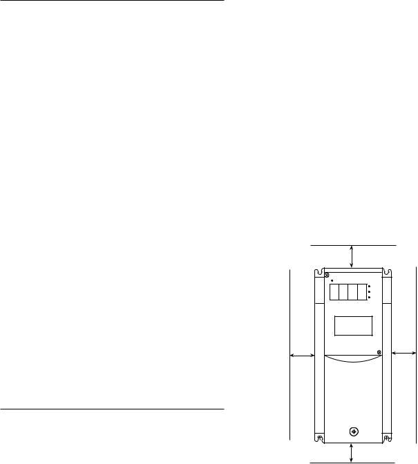
Dimensions 0.5 Hp 230 VAC
Dimensions in inches (mm)
|
|
|
|
4.33 (110) |
|
|
|
|
|
|
|
|
|
4.53 (115) |
|
|
|
|
|
|
|
|
|
|
|
|
|
|
|
|
|
|
|
|
|
|
|
||||||||||
|
|
|
3.78 (96) |
|
|
|
|
|
|
|
0.87 (22) |
|
|
|
|
|
|
|
|
||||
|
|
|
|
|
|
|
|
|
|
|
|
|
|
|
|
0.24 (6) |
|||||||
|
|
|
|
|
|
|
|
|
|
|
|
|
|
|
|
|
|
|
|
||||
|
|
0.28 (7) |
|
|
|
|
|
|
|
0.28 (7) |
|
|
|
|
|
|
|
|
|
|
|
||
|
|
|
|||||||||||||||||||||
|
|
|
|
|
|
|
|
|
|
|
|
|
|
|
|
|
|
|
|
|
|
|
|
0.24 (6) 
9.69 (246) |
10.24 (260) |
|
.28 (7) |
0.24 (6) |
2.52 (64) |
 1.26 (32)
0.87 (22)
BUSHING SUPPLIED
2.52 (64)
3-2

Dimensions 1 Hp 230 VAC
Dimensions in inches (mm)
|
|
|
|
4.33 (110) |
|
|
|
|
|
|
|
|
|
|
512 (130) |
|
|
|
|
|
|
|
1.46 |
(37) |
|
|
|
|
|
|
|
|
|
|
|
|
|
|
|
|
|||||||||
|
|
|
3.78 (96) |
|
|
|
|
|
|
|
|
|
|
|
|
|
|
|
|
|
|
|||
|
|
|
|
|
|
|
|
|
|
|
|
|
|
|
|
|
|
|
|
|||||
|
|
0.28 (7) |
|
|
|
|
|
|
|
0.28 (7) |
|
|
|
|
|
|
|
|
|
|
0.24 |
(6) |
||
|
|
|
||||||||||||||||||||||
|
|
|
|
|
|
|
|
|
|
|
|
|
|
|
|
|
|
|||||||
|
|
|
|
|
|
|
|
|
|
|
|
|
|
|
|
|
|
|
|
|
|
|
|
|
0.24 (6) 
9.69 (246) |
10.24 (260) |
|
.28 (7) |
0.24 (6) |
3.11 (79) |
 1.26 (32)
(79)3.11
0.87 (22)
BUSHING SUPPLIED
3-3
Dimensions 2, 3, 5 Hp 230 VAC and 1, 2, 3, 5 Hp 460 VAC
Dimensions in inches (mm)
|
|
|
5.91 (150) |
|
|
|
|
|
|
|
|
|
|
5.71 (145) |
|
|
|
|
|
|
|
|
|
|
|
|
|
|
|
|
|
|
|
|
|
|
|
||||||||||||
|
|
|
|
5.35 (136) |
|
|
|
|
|
|
|
|
|
|
|
|
|
|
|
|
|
|
2.05 |
(52) |
|
|
0.28 (7) |
|
|
|
|
|
|
|
|
0.28 (7) |
|
|
|
|
|
|
|
|
|
|
0.24 |
(6) |
|
|
|
|
||||||||||||||||||||||
|
|
|
|
|
|
|
|
|
|
|
|
|
|
|
|
|
|
|
|
|||||
|
|
|
|
|
|
|
|
|
|
|
|
|
|
|
|
|
|
|
|
|
|
|
|
|
0.24 (6) 
9.69 (246) |
10.24 (260) |
|
.28 (7) |
0.24 (6) |
3.7 (94) |
1.26 (32)
1.26 (32) 
0.87 (22)
BUSHING SUPPLIED
3.7 (94)
3-4

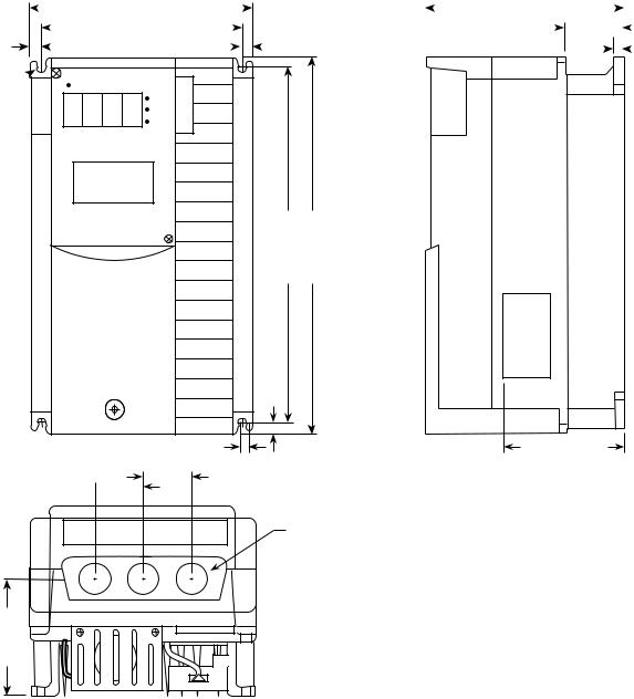
Dimensions 7.5 , 10 Hp 230 and 460 VAC
Dimensions in inches (mm)
8.66 (220) |
|
|
7.68 (195) |
|
|
|
|
7.72 (196) |
0.47 (12) |
3.82 (97) |
|
0.47 (12) |
0.47 (12) |
0.39 (10) |
|
|
|
||
|
|
|
|
|
9.37 (238) |
10.24 (260) |
|
|
0.39 (10) |
|
|
|
0.39 (10) |
|
6.18 (157) |
|
|
|
|
2.07 (52.5)
1.81 (46)
2.26 (57.5)
0.87 (22)
BUSHING SUPPLIED
6.18 (157)
3-5
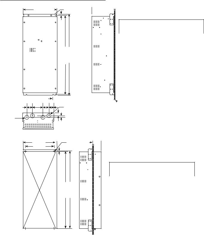
Dimensions 15, 20, 25, 30 Hp 230 and 460 VAC
Dimensions in inches (mm)
2-0.39 (10)
 9.84 (250)
  8.90 (226)
 0.47 (12)
0.47 (12)
0.47 (12)
14.88 (378) |
15.75 (400) |
0.39 (10)
.0.39 (10) 

|
2.42 (61.5) |
2.17 (55) |
BUSHING SUPPLIED |
2.48 (63) |
|
1.34 (34) |
1.65 (42) |
5.93 (150.5)
7.68 (195)
3.78 (96) 


 0.39 (10)
6.02 (153)
3-6
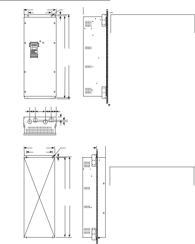
Dimensions 35 , 40 Hp 460 VAC
Dimensions in inches (mm)
BACK PANEL MOUNTING
13.4 (340) |
2-ø 0.4 (10) |
|
9.5 (240) |
|
|
|
0.5 (12) |
|
AF-300E$ |
|
|
|
32.7 (830) |
33.5 (850) |


 0.4 (10)
2.63.8 2.8 2.3
(65) (97) (70) (58)
4-ø 1.9 (48) wire inlet  Knock out hole
1.6 (41) |
1.0 (25) |
THROUGH PANEL MOUNTING |
|
12.8 (326) |
4-MB (0.3) |
9.5 (240) |
|
0.4 (9) |
|
32.0 (812) |
32.7 (830) |
 9.7 (245)
 0.1 (2.3)


AF-300E$ Back-Panel Mounting: Interior Watts Loss
Hp (CT) |
0 setting |
10 setting |
Hp (VT) |
0 setting |
10 setting |
35 |
|
|
40 |
650 |
850 |
40 |
850 |
1100 |
50 |
900 |
1050 |
 BACK PANEL
 4.1 (105)
AF-300E$ Thru-Panel Mounting: Interior Watts Loss
Hp (CT) |
0 setting |
10 setting |
Hp (VT) |
0 setting |
10 setting |
35 |
|
|
40 |
195 |
255 |
40 |
255 |
330 |
50 |
270 |
315 |
 BACK PANEL
3-7

Dimensions 50 Hp 460 VAC
Dimensions in inches (mm)
BACK PANEL MOUNTING
14.8 (375) |
|
2-ø 0.4 (10) |
|
 10.8 (275)


0.5 (12)
AF-300E$
|
|
|
|
|
|
|
|
|
|
|
32.7 (830) |
33.5 (850) |
|
|
|
|
|
|||
|
|
|
|
|||
|
|
|
|
|||
|
|
|
|
|||
 0.4 (10)
2.63.8 2.8 2.3
(65) (97) (70) (58)
4-ø 1.9 (48) wire inlet  Knock out hole
1.6 (41) |
1.0 (25) |
THROUGH PANEL MOUNTING |
|
14.2 (361) |
4-MB (0.3) |
10.8 (275) |
|
0.4 (9) |
|
32.0 (812) |
32.7 (830) |
 9.7 (245)
 0.1 (2.3)


AF-300E$ Back-Panel Mounting: Interior Watts Loss
Hp (CT) |
0 setting |
10 setting |
Hp (VT) |
0 setting |
10 setting |
50 |
900 |
1200 |
60 |
950 |
1150 |
 BACK PANEL
 4.1 (105)
AF-300E$ Thru-Panel Mounting: Interior Watts Loss
Hp (CT) |
0 setting |
10 setting |
Hp (VT) |
0 setting |
10 setting |
50 |
270 |
360 |
60 |
285 |
345 |
 BACK PANEL
3-8

Dimensions 60, 75 Hp 460 VAC
Dimensions in inches (mm)
BACK PANEL MOUNTING
14.8 (375) |
2-ø 0.4 (10) |
|
10.8 (275) |
|
|
|
0.5 (12) |
|
AF-300E$ |
|
|
|
38.61 (980) |
39.4 (1000) |
|
|
0.4 (10) |
|
|
2.6 |
3.8 |
2.8 |
3.7 |
|
(65) |
(100) |
(70) (93) |
|
|
4-ø 1.9 (48) |
|
|
|
|
wire inlet |
|
|
|
|
Knock out hole |
|
|
1.6 (41) |
0.4 (10) |
|
|
|
||
THROUGH PANEL MOUNTING
14.2 (361) |
|
4-M8 (0.3) |
|
 10.8 (275)
0.4 (9)
37.9 (962) |
38.6 (980) |
 9.7 (245)
 0.1 (2.3)


AF-300E$ Back-Panel Mounting: Interior Watts Loss
Hp (CT) |
0 setting |
10 setting |
Hp (VT) |
0 setting |
10 setting |
60 |
1000 |
1300 |
75 |
1050 |
1250 |
75 |
1150 |
1550 |
100 |
1300 |
1500 |
 BACK PANEL
 4.1 (105)
AF-300E$ Thru-Panel Mounting: Interior Watts Loss
Hp (CT) |
0 setting |
10 setting |
Hp (VT) |
0 setting |
10 setting |
60 |
300 |
390 |
75 |
315 |
375 |
75 |
345 |
415 |
100 |
390 |
450 |
 BACK PANEL
3-9

Dimensions 100 Hp 460 VAC
Dimensions in inches (mm)
BACK PANEL MOUNTING
14.8 (375) |
|
106 (270) |
|
|
|
|
|
2-ø 0.4 (10) |
|
|
|
|
|
||
10.8 (275) |
|
0.1 (2.3) |
|
|
|
|
|
|
(12) |
AF-300E$ Back-Panel Mounting: Interior Watts Loss |
|||||
|
0.5 |
||||||
|
Hp (CT) |
0 setting |
10 setting |
Hp (VT) |
0 setting |
10 setting |
|
AF-300E$ |
|
||||||
|
|
|
|
|
|
|
|
|
|
100 |
1500 |
1600 |
125 |
1700 |
1850 |
|
42.5 (1080) |
43.3 (1100) |
|
|
|
|
|


 0.4 (10)
 BACK PANEL
3.2 |
3.6 |
3.6 |
2.5 |
|
|
|
|
|
|
|
(80) |
(92) |
(92) |
(62) |
3-ø 2.5 (64) |
|
|
|
|
|
|
|
|
|
|
wire inlet |
|
|
|
|
|
|
4 ø 1.9 (48) |
|
|
|
Knock out hole |
|
|
|
|
|
|
wire inlet |
|
|
|
|
|
|
|
|
|
|
Knock out hole |
|
|
|
|
|
|
|
|
|
|
|
|
|
1.7 (43) |
|
|
|
|
|
|
|
THROUGH PANEL MOUNTING |
|
|
|
|
|
|
|
|
|
|
14.2 (361) |
|
|
4-M8 (0.3) |
4.1 (105) |
|
|
|
|
|
|
10.8 (275) |
|
|
|
|
|
|
|
|
|
|
|
|
|
0.4 (9) |
|
|
|
|
|
|
|
|
|
|
|
|
AF-300E$ Thru-Panel Mounting: Interior Watts Loss |
|||||
|
|
|
|
|
Hp (CT) |
0 setting |
10 setting |
Hp (VT) |
0 setting |
10 setting |
|
|
|
|
|
100 |
450 |
480 |
125 |
510 |
555 |
|
|
|
41.8 (1062) |
42.5 (1080) |
|
|
|
|
|
|
NOTE: Drive includes a separately mounted DC Link Reactor.
 BACK PANEL
NOTE: Drive includes a separately mounted DC Link Reactor. See Page 4-10 for details
3-10

Dimensions 125 Hp 460 VAC
Dimensions in inches (mm)
BACK PANEL MOUNTING
20.9 (530) |
|
2-ø 0.6 (15) |
|
 16.9 (430)


0.7 (18)
AF-300E$
|
|
|
|
|
47.2 (1200) |
|
|
|
45 (1170) |
||
|
|
|
|||
|
|
|
|||
|
|
|
|
|
|
|
|
|
|
|
|
3.7 |
|
|
|
|
|
|
|
|
0.4 (10) |
|
|||||
|
|
|
|
|
|
|
|
|
|
|
|
|
|
|
|
|
|
|
|
||||||||
5.9 |
|
|
5.5 |
|
2.4 |
|
|
|
|
|
|
3-ø 2.5 (64)s |
|||||||||||||||
|
|
|
|
|
|
|
|
|
|||||||||||||||||||
|
|
|
|
|
|
|
|
|
|
|
|
|
|
|
|
|
|
|
|
|
|
|
|
|
|
||
(150) |
(139) |
(94) |
(62) |
|
|
|
|
||||||||||||||||||||
|
|
|
|
|
|
|
|
||||||||||||||||||||
|
|
|
|
|
|
|
|
||||||||||||||||||||
4 ø 1.9 (48) |
|
|
|
|
|
|
|
|
|
|
|
|
|
|
|
|
|
|
|
|
|
|
|
|
|
|
|
|
|
|
|
|
|
|
|
|
|
|
|
|
|
|
|
|
|
|
|
|
|
|
|||||
wire inlet |
|
|
|
|
|
|
|
|
|
|
|
|
|
|
|
|
|
|
|
|
|
|
|
|
|
||
Knock out hole |
|
|
|
|
|
|
|
|
|
|
|
|
|
|
|
|
|
|
|
||||||||
|
|
|
|
|
|
|
1.9 (48) |
1.0 (25) |
|
|
|||||||||||||||||
|
|
|
|
|
|
|
|
|
|
|
|
|
|
|
|
|
|
||||||||||
THROUGH PANEL MOUNTING |
|
|
|
|
|
|
|
|
|
|
|
|
|
|
|
|
|
|
|
||||||||
|
|
|
|
|
|
|
|
|
20 (510) |
|
|
|
|
|
|
|
|
|
|
|
|
|
|
4-M12 0.5 |
|||
|
|
|
|
|
|
|
|
|
|
|
|
|
|
|
|
|
|
|
|
|
|
|
|||||
|
|
16.9 (430)) |
|
|
|
|
|
|
|
|
|
|
|
|
|
|
|
||||||||||
|
|
|
|
|
|
|
|
|
|
|
|
|
|
|
|
||||||||||||
|
|
|
|
|
|
|
|
|
|
|
|
|
|
|
|
|
|
|
|
||||||||
|
|
|
|
|
|
|
|
|
|
|
|
|
|
|
|
|
|
|
|
|
|||||||
|
|
|
|
|
|
|
|
|
|
|
|
|
|
|
|
0.5 (12.5) |
|
|
|
||||||||
|
|
|
|
|
|
|
|
|
|
|
|
|
|
|
|
|
|
|
|
|
|
|
|
|
|
|
|
45.1 (1145) |
46.1 (1170) |
 12.4 (315)
 0.1 (3.2)


AF-300E$ Back-Panel Mounting: Interior Watts Loss
Hp (CT) 0 setting 10 setting Hp (VT) 0 setting 10 setting
125 |
1750 |
2000 |
150 |
1800 |
2000 |
 BACK PANEL
 4.9 (125)
AF-300E$ Thru-Panel Mounting: Interior Watts Loss
Hp (CT) |
0 setting |
10 setting |
Hp (VT) |
0 setting |
10 setting |
125 |
525 |
600 |
150 |
540 |
600 |
NOTE: Drive includes a separately mounted DC Link Reactor
 BACK PANEL
NOTE: Drive includes a separately mounted DC Link Reactor. See Page 4-10 for details
3-11
Dimensions 150 Hp 460 VAC
Dimensions in inches (mm)
BACK PANEL MOUNTING
20.9 (530) |
|
2-ø 0.6 (15) |
|
 16.9 (430)


0.7 (18)
AF-300E$
|
|
|
|
|
|
|
|
|
|
|
55.9 (1420) |
57.1 (1450) |
|
|
|
|
|
|||
|
|
|
|
|||
|
|
|
|
|||
 0.6 (15)
3.25.4 3.6 2.7
(80) |
(136) |
(92) |
(68) |
3-ø 2.5 (64)s |
|
||||
ø 1.9 (48) |
|
|
|
|
wire inlet |
|
|
|
|
Knock out hole |
|
|
3.2 (81) |
0.8 (20) |
|
|
|
||
THROUGH PANEL MOUNTING |
|
|
|
|
|
20 (510) |
|
|
4-M12 0.5 |
|
16.9 (430) |
|
|
|
|
|
|
0.5 (12.5) |
|
54.9 (1395) |
55.9 (1420) |
 14.2 (360)
 0.1 (3.2)


AF-300E$ Back-Panel Mounting: Interior Watts Loss
Hp (CT) |
0 setting |
10 setting |
Hp (VT) |
0 setting |
10 setting |
150 |
2050 |
2350 |
200 |
2050 |
2300 |
 BACK PANEL
 5.5 (140)
AF-300E$ Thru-Panel Mounting: Interior Watts Loss
Hp (CT) |
0 setting |
10 setting |
Hp (VT) |
0 setting |
10 setting |
150 |
615 |
705 |
200 |
615 |
690 |
NOTE: Drive includes a separately mounted DC Link Reactor.
 BACK PANEL
NOTE: Drive includes a separately mounted DC Link Reactor. See Page 4-10 for details
3-12
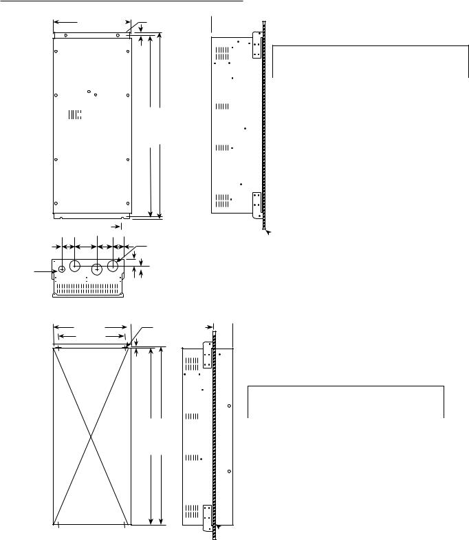
Dimensions 200 Hp 460 VAC
Dimensions in inches (mm)
BACK PANEL MOUNTING
20.9 (530) |
|
2-ø 0.6 (15) |
|
 16.9 (430)


0.7 (18)
AF-300E$
|
|
|
|
|
|
|
|
|
|
|
55.9 (1420) |
57.1 (1450) |
|
|
|
|
|
|||
|
|
|
|
|||
|
|
|
|
|||
|
|
|
|
|||
|
|
|
|
|||
 0.6 (15)
3.76.4 5.4 3.4
(95) |
(162) |
(138) (86) |
3-ø 2.5 (90) |
|
|||
4 ø 1.9 (48) |
|
|
|
wire inlet |
|
|
|
Knock out hole |
|
2.8 (71) |
0.6 (15) |
|
|
||
THROUGH PANEL MOUNTING |
|
|
|
|
20 (510) |
4-M12 0.5 |
|
|
16.9 (430) |
|
|
|
|
0.5 (12.5) |
|
54.9 (1395) |
55.9 (1420) |
 14.2 (360)
 0.1 (3.2)


AF-300E$ Back-Panel Mounting: Interior Watts Loss
Hp (CT) |
0 setting |
10 setting |
Hp (VT) |
0 setting |
10 setting |
200 |
2850 |
3250 |
250 |
2800 |
3150 |
 BACK PANEL
 5.5 (140)
AF-300E$ Thru-Panel Mounting: Interior Watts Loss
Hp (CT) |
0 setting |
10 setting |
Hp (VT) |
0 setting |
10 setting |
200 |
855 |
975 |
250 |
840 |
945 |
NOTE: Drive includes a separately mounted DC Link Reactor
 BACK PANEL
NOTE: Drive includes a separately mounted DC Link Reactor. See Page 4-10 for details
3-13
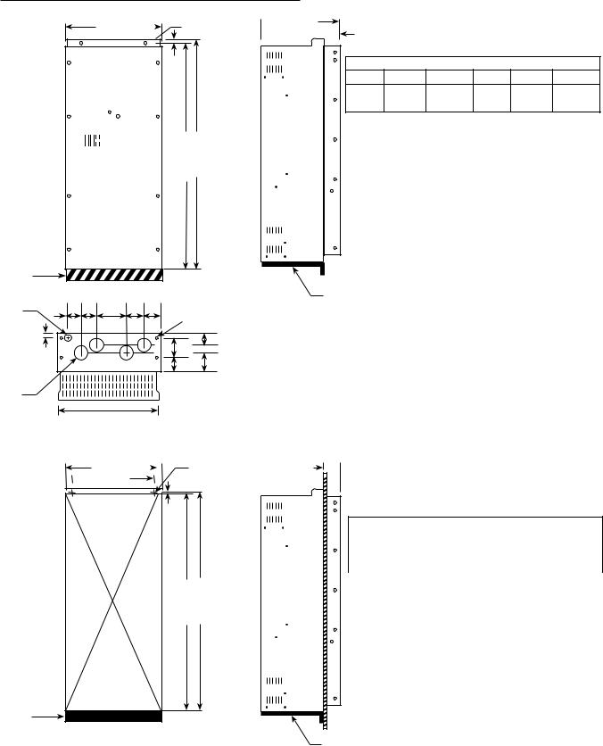
Dimensions 250, 300 Hp 460 VAC
Dimensions in inches (mm)
BACK PANEL MOUNTING
26.8 (680) |
|
2-ø 0.6 (15) |
|
 22.8 (580)


0.7 (18)
AF-300E$
|
|
|
|
|
|
|
|
|
|
|
56.3 (1430) |
57.1 (1450) |
|
|
|
|
|
|||
|
|
|
|
|||
|
|
|
|
|||
|
|
|
|
|||
|
|
|
|
|||
|
|
|
|
|||
BRACKET AREA (BRACKET SUPPLIED BY OTHERS, MUST BE CAPABLE OF SUPPORTING 500 LBS. MIN.)
4 ø 1.9 (48) |
|
2.4 |
4.3 |
6.7 |
4.9 |
5.3 |
4-ø 0.6 (15) |
||
wire inlet |
|
|
|
|
|||||
Knock out hole |
1.6 (41) |
(60) |
(110) |
(170) |
(125)(134) |
|
|
|
|
|
|
|
|
||||||
|
|
|
|
|
43. |
(110) |
3 |
(75) |
|
|
|
|
|
|
|
3.9 |
(100) |
1.6 |
(40) |
4-ø 3.5 (90) |
|
wire inlet |
|
Knock out hole |
24 (610) |
|
 14.2 (360) 4.5 (115)

AF-300E$ Back-Panel Mounting: Interior Watts Loss
Hp (CT) 0 setting 10 setting Hp (VT) 0 setting 10 setting
250 |
3500 |
4000 |
300 |
3450 |
3800 |
300 |
3850 |
4450 |
350 |
3900 |
4300 |
BRACKET REQUIRED FOR MOUNTING
THROUGH PANEL MOUNTING
26 (660) |
|
2-M12 0.56 |
|
 22.8 (580)
0.4 (10)
55.7 (1415) |
56.3 (1430) |
BRACKET AREA (BRACKET SUPPLIED BY OTHERS, MUST BE CAPABLE OF SUPPORTING 500 LBS. MIN.)
NOTE: Drive includes a separately mounted DC Link Reactor
 4.5 (115)
AF-300E$ Thru-Panel Mounting: Interior Watts Loss
Hp (CT) |
0 setting |
10 setting |
Hp (VT) |
0 setting |
10 setting |
250 |
1050 |
1200 |
300 |
1035 |
1140 |
300 |
1155 |
1335 |
350 |
1170 |
1290 |
 BACK PANEL
BRACKET REQUIRED FOR MOUNTING
NOTE: Drive includes a separately mounted DC Link Reactor. See Page 4-10 for details
3-14

Keypad Mounting Hole (Panel Cutting)
Dimensions in inches (mm)
3-15
 Loading...