


 Loading...
GE Energy
Industrial Solutions
EntelliGuard® TU Trip Units
Installation, Operation, and Maintenance Manual
For UL/ANSI trip units used in the following circuit breakers:
•EntelliGuard G
•WavePro
•AK, AKR
•Conversion Kits
•Power Break
•Power Break II

ii |
©2012 General Electric All Rights Reserved |
HAZARD CLASSIFICATIONS
The following important highlighted information appears throughout this document to warn of potential hazards or to call attention to information that clarifies a procedure.
Carefully read all instructions and become familiar with the devices before trying to install, operate, service or maintain this equipment.
DANGER
Indicates a hazardous situation that, if not avoided, will result in death or serious injury.
WARNING
Indicates a hazardous situation that, if not avoided, could result in death or serious injury.
CAUTION
Failure to comply with these instructions may result in product damage.
NOTICE
Indicates important information that must be remembered and aids in job performance.
TRADEMARKS
EntelliGuard® |
WavePro® |
Power Break® |
Power +® |
MicroVersaTrip® |
EPIC® |
ProTrip® |
|
WARRANTY |
|
This document is based on information available at the time of its publication. While efforts have been made to ensure accuracy, the information contained herein does not cover all details or variations in hardware and software, nor does it provide for every possible contingency in connection with installation, operation, and maintenance. Features may be described herein that are not present in all hardware and software systems. GE Industrial Solutions assumes no obligation of notice to holders of this document with respect to changes subsequently made. GE Industrial Solutions makes no representation or warranty, expressed, implied, or statutory, with respect to, and assumes no responsibility for the accuracy, completeness, sufficiency, or usefulness of the information contained herein. No warrantees of merchantability or fitness for purpose shall apply.
Contact your local sales office if further information is required concerning any aspect of EntelliGuard G, AKR, Power Break, Power Break II and WavePro circuit breaker operation or maintenance.
©2012 General Electric All Rights Reserved |
iii |

EntelliGuard TU Trip Units: UL/ANSI Models |
DEH-4567B |
|
TABLE OF CONTENTS |
|
|
SECTION 1. |
General Information ................................................................................................................................................................ |
1 |
Front Panel Display ............................................................................................................................................................................................................................ |
1 |
|
Menu Access.......................................................................................................................................................................................................................................... |
2 |
|
Electrical Requirements................................................................................................................................................................................................................... |
3 |
|
Equipment Interfaces........................................................................................................................................................................................................................ |
3 |
|
Definitions |
............................................................................................................................................................................................................................................... |
3 |
GTU Order ...................................................................................................................................................................................................................................Code |
4 |
|
Setup Software..................................................................................................................................................................................................................................... |
4 |
|
Installing ..................................................................................................................................................................................................the Setup Software |
4 |
|
System ............................................................................................................................................................................................................Requirements |
4 |
|
Installation ............................................................................................................................................................................................................Procedure |
5 |
|
Rating Plugs ...............................................................................................................................................................................& the Universal Rating Plug |
5 |
|
WaveForm ............................................................................................................................................................................................................................Capture |
5 |
|
Event Logging .................................................................................................................................................................................................................................. |
6 |
|
SECTION 2. ................................................................................................................................................................................... |
Protection |
7 |
Overcurrent ..............................................................................................................................................................................................Protection Functions |
7 |
|
Long Time ........................................................................................................................................................................................................................Protection |
7 |
|
Long Time ...........................................................................................................................................................................................................................Pickup |
7 |
|
Long Time .............................................................................................................................................................................................................................Delay |
7 |
|
Thermal ............................................................................................................................................................................................Long Time Overcurrent |
7 |
|
Thermal ............................................................................................................................................................................................................................Memory |
8 |
|
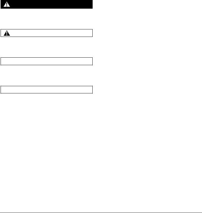
Fuse Shaped ....................................................................................................................................................................Steep Long Time Overcurrent |
8 |
|
Short Time .......................................................................................................................................................................................................................Protection |
9 |
|
Short Time ..........................................................................................................................................................................................................................Pickup |
9 |
|
Short Time .........................................................................................................................................................................................................................Delay |
10 |
|
Short Time ..........................................................................................................................................................................................................................Slope |
10 |
|
Instantaneous ............................................................................................................................................................................................................Protection |
11 |
|
WaveForm ......................................................................................................................................................................Recognition vs. Peak Sensing |
11 |
|
Reduced .................................................................................................................................................................................Energy Let Through (RELT) |
11 |
|
Ground Fault ...............................................................................................................................................................................................................Protection |
12 |
|
Ground Fault .......................................................................................................................................................................................................Summation |
12 |
|
Ground Fault ...........................................................................................................................................................................................................................CT |
12 |
|
Ground- ...................................................................................................................................................................................................................Fault Delay |
13 |
|
Alarms .................................................................................................................................................................................................................................................... |
|
13 |
Ground Fault .................................................................................................................................................................................................................Alarms |
13 |
|
Current Alarm................................................................................................................................................................................................................................ |
13 |
|
Zone Selective .........................................................................................................................................................................................................Interlocking |
14 |
|
ZSI Option........................................................................................................................................................................................................................................ |
15 |
|
Interruption ..................................................................................................................................................................................................................Protection |
16 |
|
Making Current .............................................................................................................................................................................................Release (MCR) |
16 |
|
High Set ..................................................................................................................................................................Instantaneous Protection (HSIOC) |
16 |
|
Breaker ...........................................................................................................................................................................................Interface Module (BIM) |
16 |
|
BIM Transaction ......................................................................................................................................................................................................Details |
16 |
|
Protective ..............................................................................................................................................................................................................................Relays |
17 |
|
Voltage .....................................................................................................................................................................................................................Unbalance |
17 |
|
Current Unbalance..................................................................................................................................................................................................................... |
17 |
|
Undervoltage ...................................................................................................................................................................................................................Relay |
17 |
|
Zero Voltage .........................................................................................................................................................................................................................Trip |
17 |
|
Overvoltage .......................................................................................................................................................................................................................Relay |
17 |
|
Power Reversal ................................................................................................................................................................................................................Relay |
18 |
|
Power .........................................................................................................................................................................................................Direction Setup |
18 |
|
Potential ........................................................................................................................................................................................Transformer Voltage |
18 |
|
iv |
©2012 General Electric All Rights Reserved |

DEH-4567B |
EntelliGuard TU Trip Units: UL/ANSI Models |
|
Potential Transformer Connection................................................................................................................................................................................ |
|
19 |
Output Relays...................................................................................................................................................................................................................................... |
|
19 |
Fan/Command Close Control................................................................................................................................................................................................ |
|
19 |
Bell Alarm Accessory....................................................................................................................................................................................................................... |
|
20 |
Bell Alarm with Lock-out Accessory Configuration Setup (applies to Power Break II and WavePro Trip Units only) |
.............20 |
|
Settings Description .............................................................................................................................................................................................................. |
|
20 |
Bell Alarm Operation – EntelliGuard G breakers ......................................................................................................................................................... |
|
20 |
Digital Input Relays .......................................................................................................................................................................................................................... |
|
21 |
SECTION 3. Setting up the Trip Unit ....................................................................................................................................................... |
|
22 |
Setup Navigation .............................................................................................................................................................................................................................. |
|
22 |
Long Time Pickup.............................................................................................................................................................................................................................. |
|
22 |
Long Time Delay................................................................................................................................................................................................................................ |
|
22 |
Short Time Pickup ............................................................................................................................................................................................................................. |
|
22 |
Short Time Delay ............................................................................................................................................................................................................................... |
|
22 |
Short Time Slope ............................................................................................................................................................................................................................... |
|
23 |
Instantaneous Pickup..................................................................................................................................................................................................................... |
|
23 |
RELT Instantaneous Pickup ......................................................................................................................................................................................................... |
|
24 |
Ground Fault Sum Pickup............................................................................................................................................................................................................. |
|
24 |
Ground Fault Sum Delay............................................................................................................................................................................................................... |
|
24 |
Ground Fault Sum Slope ............................................................................................................................................................................................................... |
|
24 |
Ground Fault CT Pickup (EntelliGuard G only) .................................................................................................................................................................... |
|
25 |
Ground Fault CT Delay ................................................................................................................................................................................................................... |
|
25 |
Ground Fault CT Slope.................................................................................................................................................................................................................... |
|
26 |
Ground Fault Sum Alarm .............................................................................................................................................................................................................. |
|
26 |
Ground Fault CT Alarm................................................................................................................................................................................................................... |
|
26 |
Zone Selective Interlocking Setup............................................................................................................................................................................................ |
|
26 |
Zone Selective Interlock Short Time (ST) Setup ................................................................................................................................................................. |
|
27 |
Zone Selective Interlock Ground Fault Setup..................................................................................................................................................................... |
|
27 |
Protective Relay Enabled .............................................................................................................................................................................................................. |
|
27 |
Voltage Unbalance Relay ............................................................................................................................................................................................................. |
|
27 |
Zero Voltage Tripping ..................................................................................................................................................................................................................... |
|
28 |
Undervoltage Relay ......................................................................................................................................................................................................................... |
|
28 |
Overvoltage Relay ............................................................................................................................................................................................................................ |
|
28 |
Current Unbalance Relay.............................................................................................................................................................................................................. |
|
28 |
Power Reversal................................................................................................................................................................................................................................... |
|
29 |
Output Relay – Group 1 ................................................................................................................................................................................................................. |
|
29 |
Output Relay – Group 2 ................................................................................................................................................................................................................. |
|
29 |
Output Relay – Group 3 ................................................................................................................................................................................................................. |
|
29 |
Output Relay – Group 4 and 5.................................................................................................................................................................................................... |
|
30 |
Output Relay – Group 6 ................................................................................................................................................................................................................. |
|
30 |
Output Relay – Group 7 ................................................................................................................................................................................................................. |
|
30 |
Output Relay –Group 8 .................................................................................................................................................................................................................. |
|
30 |
Output Relay – Groups 9, 10 and 11....................................................................................................................................................................................... |
|
31 |
Digital Input Configuration .......................................................................................................................................................................................................... |
|
31 |
Current Alarms ................................................................................................................................................................................................................................... |
|
31 |
Neutral Pole (EntelliGuard G only) ............................................................................................................................................................................................ |
|
32 |
Bell Alarm Lockout (PBII and WavePro only)....................................................................................................................................................................... |
|
32 |
Bell Alarm .............................................................................................................................................................................................................................................. |
|
32 |
Power Demand Interval................................................................................................................................................................................................................. |
|
33 |
Waveform Capture – Load Options ........................................................................................................................................................................................ |
|
33 |
PT Connection..................................................................................................................................................................................................................................... |
|
33 |
PT Voltage............................................................................................................................................................................................................................................. |
|
33 |
Power Direction ................................................................................................................................................................................................................................. |
|
33 |
Frequency ............................................................................................................................................................................................................................................. |
|
34 |
©2012 General Electric All Rights Reserved |
v |

EntelliGuard TU Trip Units: UL/ANSI Models |
DEH-4567B |
|
Modbus.................................................................................................................................................................................................................................................. |
|
34 |
Date and Time.................................................................................................................................................................................................................................... |
34 |
|
Language ............................................................................................................................................................................................................................................. |
|
34 |
Screen Timeout ................................................................................................................................................................................................................................. |
34 |
|
Password Setup ................................................................................................................................................................................................................................ |
35 |
|
SECTION 4. |
Metering Screens .................................................................................................................................................................. |
36 |
Current Metering Display ............................................................................................................................................................................................................. |
36 |
|
External CT Current Metering Display (EntelliGuard G only) ...................................................................................................................................... |
36 |
|
Voltage Metering Display............................................................................................................................................................................................................. |
36 |
|
Power Metering Display: PH –PH.............................................................................................................................................................................................. |
37 |
|
Power Metering Display—PH—N .............................................................................................................................................................................................. |
37 |
|
Demand Metering Display........................................................................................................................................................................................................... |
37 |
|
Energy Metering Display............................................................................................................................................................................................................... |
37 |
|
Frequency Metering Display....................................................................................................................................................................................................... |
37 |
|
Power Factor Metering Display................................................................................................................................................................................................. |
37 |
|
SECTION 5. |
Status Screens ....................................................................................................................................................................... |
38 |
Settings Status Screen................................................................................................................................................................................................................... |
38 |
|
Output Relay Reset.......................................................................................................................................................................................................................... |
38 |
|
Pickup Status Messages............................................................................................................................................................................................................... |
38 |
|
Rating Plug Error Messages........................................................................................................................................................................................................ |
38 |
|
BIM Error Messages ........................................................................................................................................................................................................................ |
39 |
|
Breaker Status Indications .......................................................................................................................................................................................................... |
39 |
|
RELT Status Indications................................................................................................................................................................................................................. |
40 |
|
RELT Activated Indications .......................................................................................................................................................................................................... |
40 |
|
Software Revision............................................................................................................................................................................................................................. |
40 |
|
Communication Settings.............................................................................................................................................................................................................. |
41 |
|
SECTION 6. |
Event Messages ..................................................................................................................................................................... |
42 |
Long Time Trip Event Messages ............................................................................................................................................................................................... |
42 |
|
Short Time Trip Event Messages .............................................................................................................................................................................................. |
42 |
|
Instantaneous Trip Event Messages ...................................................................................................................................................................................... |
43 |
|
Ground Fault Sum Trip Event Messages .............................................................................................................................................................................. |
43 |
|
Ground Fault CT Trip Event Messages .................................................................................................................................................................................. |
44 |
|
SECTION 7. |
Trip Unit Integration ............................................................................................................................................................. |
45 |
Reduced Energy Let-Through (RELT) Switch Wiring....................................................................................................................................................... |
45 |
|
TIM1 Wiring |
.......................................................................................................................................................................................................................................... |
45 |
TIM1 Wiring Basics: .................................................................................................................................................................................................................... |
46 |
|
TIM1 Zone Wiring basics: ........................................................................................................................................................................................................ |
47 |
|
SECTION 8. |
Serial Communication ......................................................................................................................................................... |
48 |
Modbus RTU ........................................................................................................................................................................................................................................ |
48 |
|
Modbus Address Setting ......................................................................................................................................................................................................... |
48 |
|
Modbus Baud Rate and Port Configuration.................................................................................................................................................................. |
48 |
|
Modbus Function Codes.......................................................................................................................................................................................................... |
49 |
|
Modbus Network Configuration.......................................................................................................................................................................................... |
49 |
|
RS-232 and RS-485 Connections ....................................................................................................................................................................................... |
49 |
|
RS-485 Termination Considerations................................................................................................................................................................................. |
49 |
|
Grounding Shielding Considerations ................................................................................................................................................................................ |
49 |
|
Modbus RTU Message Format............................................................................................................................................................................................. |
50 |
|
EntelliGuard Trip Unit Function Code..................................................................................................................................................................................... |
50 |
|
Function Code 03H..................................................................................................................................................................................................................... |
51 |
|
Function Code 04H..................................................................................................................................................................................................................... |
51 |
|
Function Code 05H..................................................................................................................................................................................................................... |
51 |
|
Function Code 06H..................................................................................................................................................................................................................... |
52 |
|
Function Code 10H..................................................................................................................................................................................................................... |
52 |
|
Function Code 20H..................................................................................................................................................................................................................... |
53 |
|
vi |
©2012 General Electric All Rights Reserved |

DEH-4567B |
|
EntelliGuard TU Trip Units: UL/ANSI Models |
|
Error Responses................................................................................................................................................................................................................................. |
|
53 |
|
Modbus Register Map..................................................................................................................................................................................................................... |
|
53 |
|
Practical Modbus Setup................................................................................................................................................................................................................. |
|
53 |
|
Step 1: Set up the Serial Port on the Master Device.................................................................................................................................................. |
|
53 |
|
Step 2: Configure the Communication Settings on the Trip Unit: Baud Rate, Parity, Stop Bits, Modbus Slave Address/ID 54 |
|||
Step 3: Supply 24VDC to the Trip Unit, and Connect the Trip Unit to the Computer |
...............................................................................54 |
||
Step 4: Configure the Master’s Communication Parameters............................................................................................................................... |
|
54 |
|
Step 5: Attempt to Communicate with the Device .................................................................................................................................................... |
|
54 |
|
SECTION 9. |
Profibus Communication .................................................................................................................................................... |
|
55 |
Definitions |
............................................................................................................................................................................................................................................. |
|
55 |
Profibus System ..............................................................................................................................................................................................................Concept |
|
55 |
|
Profibus DP ...................................................................................................................................................................................................-Parameterization |
|
55 |
|
Communication .................................................................................................................................................................Setup and Station Addresses |
|
55 |
|
Profibus GTU .......................................................................................................................................................................................................DP Cyclic Data |
|
56 |
|
GTU Cyclic ..................................................................................................................................................................................Read Telegram Definitions |
|
56 |
|
SECTION 10. .............................................................................................................................................................. |
Battery Information |
|
58 |
Battery Function................................................................................................................................................................................................................................ |
|
58 |
|
SECTION 11. .................................................................................................................................. |
Maintenance and Troubleshooting |
|
59 |
Rating Plug ...............................................................................................................................................................................Removal and Replacement |
|
59 |
|
Battery Replacement...................................................................................................................................................................................................................... |
|
59 |
|
Troubleshooting ...................................................................................................................................................................................................................Guide |
|
60 |
|
Other General .............................................................................................................................................................................Troubleshooting Issues |
|
61 |
|
SECTION 12. ............................................................................................................................................................... |
Testing and Quality |
|
62 |
Conformal ...........................................................................................................................................................................................................................Coating |
|
62 |
|
SECTION 13. ............................................................................................................................................................................... |
Installation |
|
63 |
Trip Unit Removal ......................................................................................................................................................................................and Replacement |
|
63 |
|
Power Break .................................................................................................................I and Power Break II Insulated Case Circuit Breakers |
|
63 |
|
Trip Unit ...................................................................................................................................................................................................................Removal |
|
63 |
|
Trip Unit .........................................................................................................................................................................................................Reinstallation |
|
64 |
|
WavePro .......................................................................................................................................................................................................Circuit Breakers |
|
64 |
|
Removal....................................................................................................................................................................................................................................... |
|
64 |
|
Reinstallation ............................................................................................................................................................................................................................ |
|
64 |
|
AKR (225 ...........................................................................................................................................................A to 5000 A Frames) Circuit Breakers |
|
64 |
|
EntelliGuard .....................................................................................................................................................................G Circuit Breaker Installation |
|
65 |
|
Trip Unit ..........................................................................................................................................Removal (Figure 13-4 through Figure 13-7) |
|
65 |
|
Trip Unit .........................................................................................................................................................................................................Reinstallation |
|
65 |
|
Appendix A: ..................................................................................................................................................................GTU Nomenclature |
|
66 |
|
Appendix B: ...................................................................................................................................................Rating Plug Nomenclature |
|
72 |
|
Appendix C: .............................................................................................................................................................Modbus Register Map |
|
73 |
|
Appendix D: ..............................................................................................................GTU Coordination Curve Settings Comparison |
|
90 |
|
Appendix E: GTU ............................................................................................................................................................Pin Out Diagrams |
|
91 |
|
©2012 General Electric All Rights Reserved |
vii |

EntelliGuard TU Trip Units: UL/ANSI Models |
DEH-4567B |
TABLE OF FIGURES |
|
Figure 1-1: EntelliGuard G Trip Units .............................................................................................................................................................................................. |
1 |
Figure 1-2: Power Break II and WavePro Trip Units ............................................................................................................................................................... |
2 |
Figure 1-3: Power Break I, AK, AKR, Conversion Kit Trip Units .......................................................................................................................................... |
2 |
Figure 1-4: EntelliGuard G Trip Units .............................................................................................................................................................................................. |
2 |
Figure 1-5: Trip Unit Keypad and Functions............................................................................................................................................................................... |
2 |
Figure 2-1: Long Time Pickup Settings.......................................................................................................................................................................................... |
7 |
Figure 2-2: Long Time Delay Settings ............................................................................................................................................................................................ |
7 |
Figure 2-3: Short Time Pickup Time Current Curve................................................................................................................................................................. |
9 |
Figure 2-4: Short Time Delay ........................................................................................................................................................................................................... |
10 |
Figure 2-5: Restrained ZSI Settings.............................................................................................................................................................................................. |
15 |
Figure 2-6: Voltage Conditioner Plate Wiring — Wye......................................................................................................................................................... |
18 |
Figure 2-7: Voltage Conditioner Plate Wiring — Delta ....................................................................................................................................................... |
19 |
Figure 3-1: Short Time Slope ........................................................................................................................................................................................................... |
23 |
Figure 3-2: Ground Fault Sum Slope, Options 1 – 2 ............................................................................................................................................................ |
25 |
Figure 3-3: Ground Fault Sum Slope, Option 3 ...................................................................................................................................................................... |
25 |
Figure 7-1: RELT Connection when Using Positive Feedback from EntelliGuard TU Trip Unit...................................................................... |
45 |
Figure 7-2: RELT Connection Without Positive Feedback from EntelliGuard TU Trip Unit .............................................................................. |
45 |
Figure 7-3: TIM1 Wiring ...................................................................................................................................................................................................................... |
45 |
Figure 7-4: Incorrect and Correct TIM1 Wiring ...................................................................................................................................................................... |
46 |
Figure 7-5: Six Trip Units Connected in Parallel to a Single Downstream TIM1 Input Pair ............................................................................. |
47 |
Figure 7-6: TIM1 Zone Wiring Diagram...................................................................................................................................................................................... |
47 |
Figure 8-1: RS-232 and RS-485 Connections ......................................................................................................................................................................... |
49 |
Figure 8-2: Wiring for Shield Grounding.................................................................................................................................................................................... |
50 |
Figure 9-1: Profibus Communication Network ...................................................................................................................................................................... |
55 |
Figure 11-1: Trip Unit with Rating Plug Removed................................................................................................................................................................. |
59 |
Figure 13-1: Removing the Old Trip Unit................................................................................................................................................................................... |
64 |
Figure 13-2: Circuit Breaker without Trip Unit........................................................................................................................................................................ |
64 |
Figure 13-3: Installing the New Trip Unit................................................................................................................................................................................... |
65 |
Figure 13-4: Trip Unit Removal Sequence, Step A................................................................................................................................................................ |
65 |
Figure 13-5: Trip Unit Removal Sequence, Step B................................................................................................................................................................ |
65 |
Figure 13-6: Trip Unit Removal Sequence, Step C................................................................................................................................................................ |
65 |
Figure 13-7: Trip Unit Removal Sequence, Step D ............................................................................................................................................................... |
65 |
viii |
©2012 General Electric All Rights Reserved |

DEH-4567B |
EntelliGuard TU Trip Units: UL/ANSI Models |
|
TABLE OF TABLES |
|
|
Table 1-1: GTU Nomenclature............................................................................................................................................................................................................ |
|
4 |
Table 1-2: Trigger WaveForm Capture Events .......................................................................................................................................................................... |
|
6 |
Table 2-1: Nominal Time Delays for Thermal Shaped Long Time Bands .................................................................................................................... |
|
8 |
Table 2-2: Nominal Clearing Times for Fuse Shaped Long Time Bands ...................................................................................................................... |
|
9 |
Table 2-3: Short Time Commit Times........................................................................................................................................................................................... |
|
10 |
Table 2-4: Short Time Settings by Breaker Type and Frame........................................................................................................................................... |
|
10 |
Table 2-5: Short Time Delay Settings........................................................................................................................................................................................... |
|
10 |
Table 2-6: Maximum Instantaneous for Power Break I, Power Break II, WavePro and AKR Trip Units.................................................... |
11 |
|
Table 2-7: Instantaneous Thresholds for Power Break I, Power Break II, WavePro and AKR Trip Units.................................................. |
12 |
|
Table 2-8: Ground Fault Pickup Settings.................................................................................................................................................................................... |
|
13 |
Table 2-9: Ground Fault Time Delay Bands, 50 Hz & 60 Hz ............................................................................................................................................. |
|
13 |
Table 2-10: Voltage Unbalance Settings ................................................................................................................................................................................... |
|
17 |
Table 2-11: Current Unbalance Settings.................................................................................................................................................................................... |
|
17 |
Table 2-12: Under Voltage Settings.............................................................................................................................................................................................. |
|
17 |
Table 2-13: Over Voltage Settings................................................................................................................................................................................................. |
|
18 |
Table 2-14: Power Reversal Settings ........................................................................................................................................................................................... |
|
18 |
Table 2-15: Output Configuration ................................................................................................................................................................................................. |
|
20 |
Table 2-16: Digital Input Assignments........................................................................................................................................................................................ |
|
21 |
Table 4-1: GTU Nomenclature......................................................................................................................................................................................................... |
|
36 |
Table 8-1: Function Code 03H Example..................................................................................................................................................................................... |
|
51 |
Table 8-2: Modbus Packet Format for Function Code 03H.............................................................................................................................................. |
|
51 |
Table 8-3: Modbus Packet Format for Function Code 04H.............................................................................................................................................. |
|
51 |
Table 8-4: Modbus Packet Format for Function Code 05H.............................................................................................................................................. |
|
52 |
Table 8-5: Modbus Packet Format for Function Code 06H.............................................................................................................................................. |
|
52 |
Table 8-6: Modbus Packet Format for Function Code 10H.............................................................................................................................................. |
|
52 |
Table 8-7: Modbus Packet Format for Function Code 20 ................................................................................................................................................. |
|
53 |
Table 8-8: Slave Responses to Errors .......................................................................................................................................................................................... |
|
53 |
Table 9-1: GTU Cyclic Read Telegram Definitions................................................................................................................................................................. |
|
56 |
Table 9-2: Byte 1..................................................................................................................................................................................................................................... |
|
56 |
Table 9-3: Byte 2..................................................................................................................................................................................................................................... |
|
57 |
Table 9-4: Byte 3..................................................................................................................................................................................................................................... |
|
57 |
Table 9-5: Byte 4..................................................................................................................................................................................................................................... |
|
57 |
Table 9-6: Byte 5..................................................................................................................................................................................................................................... |
|
57 |
Table 9-7: Byte 6..................................................................................................................................................................................................................................... |
|
57 |
Table 11-1: Troubleshooting Guide .............................................................................................................................................................................................. |
|
60 |
Table A-1: EntelliGuard Trip Unit Form, Digits 1 & 2............................................................................................................................................................. |
|
66 |
Table A-2: Frame Rating (amperes) Digit 3 for AKR.............................................................................................................................................................. |
|
66 |
Table A-3: Frame Rating (amperes) Digit 3 for PowerBreak (PB1)................................................................................................................................ |
|
66 |
Table A-4: Frame Rating (amperes) Digit 3 for PowerBreak II (PB2) ............................................................................................................................ |
|
66 |
Table A-5: Frame Rating (amperes) Digit 3 for WavePro .................................................................................................................................................. |
|
66 |
Table A-6: Frame Rating (amperes) Digit 3 for EntelliGuard G Series – Factory Installed Trip Units (ALL) – ANSI/UL, Entellisys |
|
|
(ANSI/UL), IEC ............................................................................................................................................................................................................................................ |
|
67 |
Table A-7: Frame Rating (amperes) Digit 3 for *Mpact ...................................................................................................................................................... |
|
67 |
Table A-8: Frame Rating (amperes) Digit 3 for TYPE A Conversion Kits..................................................................................................................... |
|
67 |
Table A-9: Frame Rating (amperes) Digit 3 for Compact VCB (Medium Voltage) ................................................................................................. |
|
67 |
Table A-10: Sensor Rating (amperes): Col. 4 & 5.................................................................................................................................................................... |
|
67 |
Table A-11: OC and GF Protection Packages Col. 6 & 7 EntelliGuard G ANSI/UL OC Protection.................................................................. |
68 |
|
Table A-12: OC and GF Protection Packages Digits 6 & 7 EntelliGuard G ANSI/UL OC Protection with Fuse Settings .................... |
68 |
|
Table A-13: OC and GF Protection Packages Digits 6 & 7, EntelliGuard G IEC Series OC Protection ......................................................... |
68 |
|
Table A-14: OC and GF Protection Packages Digits 6 & 7, EntelliGuard G IEC Series OC Protection with Fuse Settings ................ |
69 |
|
Table A-15: OC and GF Protection Packages Digits 6 & 7, Mpact Series OC Protection (IEC) ........................................................................ |
69 |
|
Table A-16: OC and PROTECTION Definitions: Digits 6 & 7 ............................................................................................................................................... |
|
69 |
Table A-17: OC and GF Protection Packages Digits 6 & 7, WavePro .......................................................................................................................... |
|
69 |
©2012 General Electric All Rights Reserved |
|
ix |

EntelliGuard TU Trip Units: UL/ANSI Models |
DEH-4567B |
General Information |
|
Table A-18: OC and GF Protection Packages Digits 6 & 7, WavePro when Used in UL891 Switchboards with 5 Cycle Withstand |
|
Busing.......................................................................................................................................................................................................................................................... |
70 |
Table A-19: AKR, Conv. Kits with OC Protection Digits 6 & 7.......................................................................................................................................... |
70 |
Table A-20: PowerBreak I & II Digits 6 & 7 ................................................................................................................................................................................ |
70 |
Table A-21: EntelliGuard G ANSI and UL Low-cost ACB Digits 6 & 7 .......................................................................................................................... |
70 |
Table A-22: CVCB MTU IEC Medium Voltage OC Protection Digits 6 & 7.................................................................................................................. |
70 |
Table A-23: Zone Selective Interlocking Digit 8 ..................................................................................................................................................................... |
70 |
Table A-24: Advanced Features and Communications Col. 9 ....................................................................................................................................... |
71 |
Table A-25: Manual/Auto Trip Reset Col. 10............................................................................................................................................................................ |
71 |
Table A-26: Original or Replacement Trip Unit Col. 11....................................................................................................................................................... |
71 |
Table B-1: EntelliGuard G ACB Rating Plug Nomenclature.............................................................................................................................................. |
72 |
Table B-2: Legacy Rating Plug Nomenclature ....................................................................................................................................................................... |
72 |
Table B-3: ITE 4000A Sensor Akits Rating Plug Nomenclature...................................................................................................................................... |
72 |
Table C-1: Public Parameters.......................................................................................................................................................................................................... |
73 |
Table C-2: Inputs from GTU.............................................................................................................................................................................................................. |
82 |
Table C-3: Commands ........................................................................................................................................................................................................................ |
88 |
Table C-4: Discrete Inputs from GTU........................................................................................................................................................................................... |
89 |
Table D-1: ST Band Comparisons.................................................................................................................................................................................................. |
90 |
Table E-1: GTU-C Power Break I and AKR Trip Units ........................................................................................................................................................... |
91 |
Table E-2: GTU-D PowerBreak II and WavePro...................................................................................................................................................................... |
91 |
Table E-3: GTU-ACB .............................................................................................................................................................................................................................. |
92 |
Table E-4: Pin Out for Legacy Breakers ..................................................................................................................................................................................... |
93 |
Table E-5: Pin Out for GTUTK20 Test Kit..................................................................................................................................................................................... |
94 |
x |
©2012 General Electric All Rights Reserved |
DEH-4567B |
EntelliGuard TU Trip Units: UL/ANSI Models |
|
General Information |
SECTION 1. GENERAL INFORMATION
The EntelliGuard TU Trip Unit is an electronic device that interfaces with a circuit breaker. It monitors current and/or voltage and trips the breaker in the event of an overcurrent or voltage related condition. It also provides protective relay functions, advanced metering, diagnostic features, and communications. The Trip Unit can be removed or replaced in the field by de-energizing and removing the cover of the circuit breaker.
The Trip Unit drives the circuit breaker flux shifter to provide the electromechanical tripping function. A user interface is provided on the front panel to allow adjustment of the Trip Unit’s parameters.
EntelliGuard TU Trip Unit has been designed to be plug and play compatible with previous generation trip units, MicroVersa Trip, MVT RMS-9, EPIC, MVT Plus, MVT PM, Power+, and ProTrip. In addition to trip unit upgrades,
conversion kits are offered to upgrade ANSI type legacy breakers.
FRONT PANEL DISPLAY
The Trip Unit includes a graphical Liquid Crystal Display (LCD). The front panel is similar to those shown in Figure 1-1 through Figure 1-5.
When the trip unit is energized the LCD normally displays a menu of navigation options. If the trip unit is powered from an external DC supply, a backlight is provided and remains on. If the trip unit is powered from the circuit breaker’s Current Transformers alone there is no backlight, but the navigation menu is available as long as current flow is at least 20% of the breaker’s sensor rating. If the display is blank, pressing any key will turn on the menu using battery power.
Figure 1-1: EntelliGuard G Trip Units
40 Pin Connector on top (EntelliGuard G only)
Catalog Number
LCD Screen
Navigation Panel
Pin Connector on back of all trip unit types, see images below for specifics by breaker.
Date Code
Battery, 15 Pin Port
(under the cover)
Status LED
Bell Alarm with Lockout (EntelliGuard G only)
Rating plug
WARNING
BOX SIZE AND CONNECTOR CONFIGURATION COMMONALITY DOES NOT SUGGEST INTERCHANGEABILITY BETWEEN POWERBREAK II AND WAVEPRO OR POWERBREAK 1 AND AKR. THE OPTIONS ON THESE TRIP UNITS ARE DIFFERENT AND WILL CAUSE THEM TO BEHAVE AND OPERATE DIFFERENTLY.
©2012 General Electric All Rights Reserved |
1 |

EntelliGuard TU Trip Units: UL/ANSI Models |
DEH-4567B |
General Information |
|
Figure 1-2: Power Break II and WavePro Trip Units |
|
Single 50 pin connector on the back, firmware: v08.00.05
Figure 1-3: Power Break I, AK, AKR, Conversion Kit Trip Units
Single 36 pin connector on the back, firmware: v08.00.05
Figure 1-4: EntelliGuard G Trip Units
Single 50 pin connector on the back, 40 pin connector on the top, firmware: v08.00.06, or v08.00.21 depending on the underlying hardware
See Appendix E: GTU Pin Out Diagrams for the pin out |
• ENTER: Save or set into memory |
|
diagrams for each trip unit type. |
Figure 1-5: Trip Unit Keypad and Functions |
|
MENU ACCESS |
||
|
||
The trip unit has five function keys as shown in Figure 1-5. |
|
|
All SETUP, STATUS, METER and EVENTS information is |
|
|
accessed through these five keys: |
|
|
• UP: Scroll up or increment value |
|
|
• DOWN: Scroll down or decrement value |
|
|
• RIGHT: Next function or next page |
|
|
• LEFT: Previous function or previous page |
|
2 |
©2012 General Electric All Rights Reserved |

DEH-4567B |
EntelliGuard TU Trip Units: UL/ANSI Models |
|
General Information |
ELECTRICAL REQUIREMENTS
WARNING
IMPROPER INSTALLATION, OPERATION AND MAINTENANCE
Ensure only qualified personnel install, operate, service and maintain all electrical equipment.
Failure to comply with these instructions could result in death or serious injury.
PowerBreak I, PowerBreak II, WavePro, AKR and EntelliGuard G Trip Units are powered from three different sources:
•Primary Current flow: Breaker current sensors provide sufficient power to energize the LCD when at least 20% of the sensor's ampere rating is flowing.
•+24 VDC control power. This is supplied externally, via the circuit breaker’s secondary disconnect, or from the GTUTK20 test kit, or from the portable battery pack, (TVPBP and TVPBPACC). Each GTU draws 90mA maximum.
•Internal battery power: Powers the unit temporarily when any keypad key is pressed. Battery power automatically turns off 20 sec after the last keypad press. The battery power supply is disabled when any current over 20% of the sensor rating is sensed through the current sensors. Breaker status (open/closed) is not reported under battery power.
Functions that require external 24 VDC:
•Communication (Modbus and Profibus)
•Zone Selective Interlocking—(Instantaneous only)
•WaveForm Capture
•Event log with time stamp
•Backlight
•Advanced Metering
•Relaying
•Input/output Contacts
•RELT – Reduced Energy Let Through
NOTICE
If 24 VDC supply drops below 22V, expect the backlight of the trip unit to dim or shut off. In order to ensure this does not happen, have a reliable, consistent source of 24VDC.
EQUIPMENT INTERFACES
PowerBreak I, PowerBreak II, WavePro, AK, AKR, Conversion Kits (for GE and other manufacturer breakers) and EntelliGuard G Circuit Breakers.
Trip units do not require direct connections to the equipment. All trip unit connections external to the breaker are made through the circuit breaker secondary disconnect.
The following trip unit interfaces are available at the secondary disconnect:
•Serial Communications (RS-485)
•Zone Selective Interlocking digital input and output
•Digital Inputs (2)
•Relay Outputs (2)
•Fan control digital output (5000A WavePro and AKR)
•Remote Close digital output (EntelliGuard G with Command Close Coils)
•Potential Transformer analog voltage Input
•Zero Sequence Current Transformer analog input
•4th Pole Iron Core/Rogowski (neutral sensor) analog input
The front panel test kit port provides an interface to the GTUTK20 digital test kit. See DEH-4568A for additional detail.
In addition, the MVT portable battery pack (TVPBP) can also be used on the GTU using the TVPBPACC adaptor cable.
DEFINITIONS
BIM: Breaker Interface Module (only on EntelliGuard G). This is a non-volatile memory device on the circuit breaker that defines the breaker’s configuration to the trip unit. The BIM stores configuration information on the breaker sensor rating, it’s interrupting capacity, and the agency requirements (UL, IEC, ANSI) the breaker meets.
RELT: Reduced Energy Let Through. A second instantaneous trip function that can be temporarily engaged during maintenance procedures to ensure the breaker trips as quickly as possible to limit arc flash damage.
ZSI: Zone Selective Interlocking: A wired signaling scheme between cascaded breakers that enhances coordination and can improve protection without impacting selectivity. Available on Short Time, Ground Fault and Instantaneous.
WFR: Wave Form Recognition is the algorithm used in the EntelliGuard G adjustable selective instantaneous trip element to discern between unfettered fault current and
©2012 General Electric All Rights Reserved |
3 |

EntelliGuard TU Trip Units: UL/ANSI Models |
DEH-4567B |
General Information |
|
the high peak, low energy let-through current allowed by a current limiting fuse or circuit breaker while in the process of melting or tripping. This algorithm allows the adjustable selective instantaneous to be set low and yet be selective in high prospective fault current systems. WFR allows circuit breakers to trip instantaneously for faults within their zone of protection while maintaining instantaneous clearing times in the 3-3.5 cycle range, depending on circuit breaker type, facilitating maximum arc flash mitigation possible with no sacrifice in selectivity.
WFC: Waveform Capture – an optional feature that captures an oscillographic record of system current and voltage at the moment the breaker trip unit is triggered.
Close and Latch Rating: the maximum fault current a circuit breaker can close into and successfully latch.
HSIOC: High Set Instantaneous Overcurrent, also known as an instantaneous Override. A fixed instantaneous function that operates if the breaker experiences a fault exceeding its Short Time Rating (Icw).
In: Trip Plug Rating in amperes. This is the current rating of the rating plug installed in the trip unit. This is the maximum Long Time pick up a trip unit can have with a specific plug installed. A sensor can be applied with plugs between 37.5% or 40% to 100% of the sensor rating. Plugs are labeled in amperes.
Icw: Short Time Withstand Rating of a particular circuit breaker in amperes. The withstand rating is defined differently within different standards, but it is always the value of current that a circuit breaker can withstand for the maximum Short Time Delay before interrupting.
IRMS: True RMS current measurement through a phase
Making Current Release (MCR): This is an instantaneous override that will trip the circuit breaker if it is closed into a fault exceeding the breaker’s close and latch rating.
X: X is a multiplier that may be applied in front of any rating value to denote a fraction of that rating. Ex: The Long Time Pickup is may be set at 0.5X of In.
xlCT: Multiples of current sensor rating (non-dimensional) GTU: Shorthand/abbreviation for EntelliGuard TU Trip Unit
GTU ORDER CODE
Below is the breakdown of what each column of the GTU order code represents. For specific possibilities see Appendix A: GTU Nomenclature. Also, find the Rating Plug order code in Appendix B: Rating Plug Nomenclature.
|
Table 1-1: GTU Nomenclature |
|
Order Code |
|
Representation |
|
|
|
Digit 1 and 2 |
|
EntelliGuard Trip Unit Form |
|
|
|
Digit 3 |
|
Frame Rating (Amperes) Short |
|
|
Circuit/Withstand |
|
|
|
Digit 4 and 5 |
|
Sensor Rating (Amperes) |
|
|
|
Digit 6 and 7 |
|
Overcurrent and Ground Fault |
|
|
Protection Packages |
|
|
|
Digit 8 |
|
Zone Selective Interlocking |
|
|
|
Digit 9 |
|
Advanced Features & |
|
|
Communications |
|
|
|
Digit 10 |
|
Manual/Auto Trip Reset |
|
|
|
Digit 11 |
|
Original or Replacement Trip Unit |
|
|
|
Digits 12, 13, |
|
RESERVED (Future) |
14, and 15 |
|
|
|
|
|
SETUP SOFTWARE
The EntelliGuard Setup Software provides a graphical user interface (GUI) to configure and monitor the operation of EntelliGuard Trip Unit functions. The software allows you to save setting files offline to be loaded or compared with current settings. It provides a means of creating documentation regarding all the trip unit settings.
The software also provides a tool to extract and view captured waveforms from EntelliGuard trip units equipped with optional the Waveform Capture feature. This feature also provides a means of determining harmonic content of the power system.
The EntelliGuard Setup software is available at no charge from either the GE EntelliGuard CD or the GE Industrial Solutions web-site.
In on-line mode the tool is connected over communication networks - Serial or Ethernet, you can communicate with an EntelliGuard device in real-time.
In off-line (Disconnected) mode, a settings file can be created for eventual downloading to the device.
Installing the Setup Software
The following minimum requirements must be met for the EntelliGuard Setup software to operate on your computer.
System Requirements
•Microsoft Windows™ 2000/XP/Vista/7 is installed and running properly.
•Minimum of 20 mb of hard disk space.
•Minimum 256 mb of RAM (512 mb recommended)
•RS-232 and/or Ethernet communication port.
4 |
©2012 General Electric All Rights Reserved |

DEH-4567B |
EntelliGuard TU Trip Units: UL/ANSI Models |
|
General Information |
Installation Procedure |
WAVEFORM CAPTURE |
Follow the procedure below to install the EntelliGuard Setup software in to your system.
•Click on the Setup Icon
•The First Screen will be the welcome screen as shown below. Opt [Next] to proceed further
•The Next will be the "License Agreement" screen. Opt [Next] to proceed further.
•The Next screen will show the system path where the setup is getting installed by default. One can change the desired system path for the setup program by clicking on [Browse].
•The system will perform installation in the specified location after checking for appropriate requirements. This may take 10 to 15 seconds. Once Installation is completed user will be prompted with a screen that has a [Finish] option.
Upon successful installation of the EntelliGuard you can view the application in either of two places
•As an Application short cut Icon on the desktop
•In Start > Programs > EntelliGuard TU > EntelliGuard Setup
One can use either of the above to start up the application on which, the Main Screen of the EntelliGuard Setup will be launched.
For further, detailed instructions on how to add a site and add a device via serial communication or Ethernet communication, check the help section on the software.
RATING PLUGS & THE UNIVERSAL RATING PLUG
The EntelliGuard TU trip system is composed of trip units and trip unit rating plugs along with the sensors and wiring provided in the circuit breaker to support the trip. Rating plugs are used to lower the Long Time adjustment range of the sensor provided in the circuit breaker.
The EntelliGuard TU trip rating plugs are unique in that they can be used with multiple trip units and circuit breakers within a specific sensor range, rather than only with a single specific sensor. The trip rating plug catalog number identifies the rating as well as the minimum and maximum sensor rating the plug may be used with. Appendix B lists trip-rating plugs available for each sensor and their part numbers and the two-digit codes used within the trip rating plug catalog numbers to identify sensor current ratings.
ANSI and UL circuit breaker types use a fixed rating plug with a marked ampere rating. Trip units use the current sensors installed in the breaker.
A total of eight cycles are captured:
•Four pre-trigger.
•Four post-trigger.
24 VDC external power is required for waveform capture.
When waveform capture is executed, the following channels will be captured simultaneously: Phase A current, Phase B Current, Phase C Current, Phase N Current, Phase L1 voltage, Phase L2 voltage, Phase L3 voltage.
WFC captures 48 samples per cycle, per phase, at 50 hz and 40 samples per cycle at 60 hz – the same data it used for its protection algorithms. The GE Setup Software contains full Waveform retrieval and viewer capability. GE offers the software free via web download. There is a function in the software that allows you to clear captured waveforms. The GTU stores only one waveform record at a time.
There are COMTRADE format viewers available to interpret the file downloaded from the trip unit, but the GE Setup Software is able to display the waveform graphically.
Viewing the waveform capture is described in the setup software. Currently, the software must be in communication with the trip unit prior to and during the event in order for the event to be captured. After the capture the software will show a file is available. The user then uses the software to request the file, which is extracted from the trip unit. At that point the file can be saved off for external use, or it can be opened for viewing in the program’s waveform viewer.
Harmonic content is calculated from the waveform data by the Setup Software. There is no harmonic content calculation performed by the trip unit – the data is extracted from the data set by the GE Setup software.
1.While a waveform capture data (in COMMTRADE format) is in memory, a new event will overwrite the capture data in memory. Whether the waveform capture is disabled or not, no other event is entertained. Unless and until the waveform is read and cleared by master by issuing appropriate commands, any read of waveform capture data will return the same first waveform, even if other events have occurred in between.
2.When the Modbus master is reading captured waveform data and a valid Event (trigger) occurs (for which the waveform could be captured): This new event is ignored. Since the trip unit already has an event captured and hence responding for the same event, trip unit will ignore the latest event (trigger). The trip unit will start capturing the new waveform only after Master has read the complete waveform AND issued a
©2012 General Electric All Rights Reserved |
5 |

|
EntelliGuard TU Trip Units: UL/ANSI Models |
DEH-4567B |
|
|
General Information |
|
|
|
command to clear the waveform data in trip unit |
|
|
|
memory. |
|
|
|
Table 1-2: Trigger WaveForm Capture Events |
|
|
|
Event |
Waveform Capture Setpoint |
|
|
Manual trigger over |
ON, OFF |
|
|
communications |
|
|
|
Over current (GF, ST, LT, |
ON, OFF |
|
|
Inst) |
|
|
|
Protective relays |
ON, OFF |
|
|
Current alarm 1 |
ON, OFF |
|
|
Current alarm 2 |
ON, OFF |
|
Event Logging
The trip unit keeps a log of the last 10 events:
•Over current trips
•Protective relay trips
•Shunt trip (PBII and Global EntelliGuard G Trip Units Only)
•Under voltage Release trip (PBII and Global EntelliGuard G Trip Units Only)
•BIM Trip Unit Mismatch - Breaker Interface Module (EntelliGuard G only)
NOTICE
SOFTWARE REVISION 08.00.23 AND GREATER:
If a BIM read fails the trip unit will not open the breaker, instead it will modify its internal configuration to match the AIC rating of the least capable breaker in the family. The trip unit will periodically read the BIM after that, and on a successful match the original settings will be restored. While the BIM error persists a BIM Err message will be displayed on the LCD.
The following information is stored with each event:
•RMS currents
•Phase
•Type of trip
•Trip counter
•Time and date stamps (Trips are logged under self power without time stamp. Events with time stamps are only logged when +24 VDC control power is available.)
6 |
©2012 General Electric All Rights Reserved |
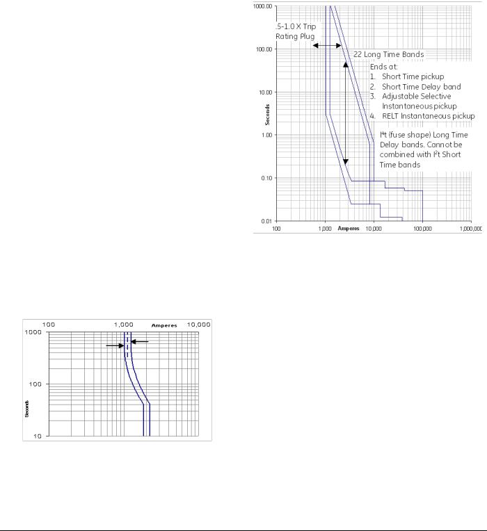
DEH-4567B |
EntelliGuard TU Trip Units: UL/ANSI Models |
|
Protection |
SECTION 2. PROTECTION
OVERCURRENT PROTECTION FUNCTIONS
The Trip Unit provides the following over current protections:
•Long Time (L)
•Short Time (S)
•Instantaneous (I, H=high range)
•Reduced Energy Let Through Instantaneous (RELT)
•Ground Fault Internal Summation (G)
•Ground Fault CT External Summation (C, EntelliGuard G only)
•Instantaneous Override (HSIOC)
•Making Current Release (MCR)
LONG TIME PROTECTION
Long Time Pickup
This setpoint establishes the breaker's nominal ampere rating, xLT, as a fraction of the rating plug value, xIn:
xLT = LT multiplier x xIn
The adjustment range for long time pickup settings is 0.50 to 1.00 times xIn in steps of 0.05. The pickup value has a 10% tolerance. The band is drawn at 1/(1+10%) and 1/1- 10%). The actual long time pickup is increased by 12% over the nominal so that 100% nominal current may be carried indefinitely. So a 1000 A setting is placed at 1120 A with the minimum pickup drawn (left side of band) is 1088A, and the maximum pickup (right side of band) is drawn at 1244A. Figure 2-1 shows the Long Time pickup setting.
Figure 2-1: Long Time Pickup Settings
Long Time Delay
The trip unit provides up to 44 long time delay bands (only on trip unit models starting with “J”). Not all circuit breakers have all bands available. There are 22 bands using a logarithmic type curve resembling the overcurrent
response of a thermal magnetic circuit breaker. And available i4t option adds 22 bands that simulate the overcurrent response of fuses. The EntelliGuard circuit breaker is able to use all 44 bands. Power Break I, Power Break II, WavePro and AKR circuit breakers use the 19 lower thermal CB-type bands and the 22 fuse-type bands.
Figure 2-2: Long Time Delay Settings
Thermal Long Time Overcurrent
The thermal I2T shape is similar to the typical curve of a thermal magnetic circuit breaker and matches the shape of many overcurrent devices used in industry today. The typical shape and range of settings may be seen in Figure 2-2. The range of time delays is shown in Table 2-1 at various multiples of nominal (100%) current setting. Drawn bands also include a mechanical constant time to account for circuit breaker operating and clearing time, which causes the slight widening of the band evident at the lower (right) end of the faster (lower) bands.
©2012 General Electric All Rights Reserved |
7 |

EntelliGuard TU Trip Units: UL/ANSI Models |
DEH-4567B |
Protection |
|
Thermal Memory
The Long Time and Short Time pick up algorithm also includes a cooling cycle that keeps track of current if it oscillates in and out of pick up range. This Thermal Memory is also active in case the circuit breaker trips on Long Time or Short Time to account for residual heating in conductors. If a circuit breaker is closed soon after a Long Time trip or Short Time trip, a subsequent trip may happen faster than indicated by the time current curve due to the residual cable Thermal Memory effect. In trips without control power, the Thermal Memory is powered from the trip battery. The cooling algorithm requires up to 14 minutes to fully reset to zero.
Table 2-1 shows the nominal clearing and commit times for X multipliers of nominal pickup.
Table 2-1: Nominal Time Delays for Thermal Shaped Long Time Bands
X = |
1.5 |
1.5 |
6 |
6 |
7.2 |
7.2 |
10 |
10 |
|
Commit |
Clear |
Commit |
Clear |
Commit |
Clear |
Commit |
Clear |
Min CB |
4.25 |
8.04 |
0.20 |
0.33 |
0.14 |
0.24 |
0.072 |
0.137 |
C-2 |
12.7 |
24.1 |
0.60 |
0.94 |
0.42 |
0.66 |
0.21 |
0.35 |
C-3 |
25.5 |
48.1 |
1.21 |
1.84 |
0.83 |
1.28 |
0.43 |
0.67 |
C-4 |
34.0 |
64.1 |
1.61 |
2.45 |
1.11 |
1.70 |
0.57 |
0.89 |
C-5 |
51.0 |
96.2 |
2.41 |
3.66 |
1.67 |
2.53 |
0.86 |
1.32 |
C-6 |
67.9 |
128 |
3.21 |
4.87 |
2.22 |
3.37 |
1.15 |
1.75 |
C-7 |
84.9 |
160 |
4.02 |
6.08 |
2.78 |
4.20 |
1.43 |
2.18 |
C-8 |
102 |
192 |
4.82 |
7.29 |
3.33 |
5.03 |
1.72 |
2.61 |
C-9 |
119 |
224 |
5.62 |
8.49 |
3.89 |
5.87 |
2.01 |
3.03 |
C-10 |
136 |
256 |
6.43 |
9.70 |
4.44 |
6.70 |
2.29 |
3.46 |
C-11 |
153 |
289 |
7.23 |
10.9 |
5.00 |
7.54 |
2.58 |
3.89 |
C-12 |
170 |
321 |
8.04 |
12.1 |
5.56 |
8.37 |
2.87 |
4.32 |
C-13 |
204 |
385 |
9.64 |
14.5 |
6.67 |
10.0 |
3.44 |
5.18 |
C-14 |
238 |
449 |
11.2 |
17.0 |
7.78 |
11.7 |
4.01 |
6.04 |
C-15 |
272 |
513 |
12.9 |
19.4 |
8.89 |
13.4 |
4.59 |
6.90 |
C-16 |
306 |
577 |
14.5 |
21.8 |
10.0 |
15.0 |
5.16 |
7.76 |
C-17 |
340 |
641 |
16.1 |
24.2 |
11.1 |
16.7 |
5.73 |
8.61 |
C-18 |
374 |
705 |
17.7 |
26.6 |
12.2 |
18.4 |
6.30 |
9.47 |
Max CB |
408 |
769 |
19.3 |
29.1 |
13.3 |
20.0 |
6.88 |
10.3 |
•Algorithm will not commit below 1.5 cycles, clearing time will not be less than 0.088 seconds.
•Actual Long Time pickup is 112% of nominal pickup.
Fuse Shaped Steep Long Time Overcurrent
The optional steeper fuse characteristic is a straight line K=I4t shape for application in systems where fuses and circuit breakers are used together. Twenty-two different time bands are available in each trip unit. Figure displays minimum and maximum bands. Table 2-2 displays the nominal time delays for each of the 22 bands at various multiples of nominal current pickup.
Drawn bands also include a constant time component, which accounts for the slight widening evident in the time current curve at the lower (right) end of the faster (lower) time bands.
8 |
©2012 General Electric All Rights Reserved |
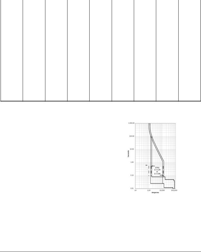
|
DEH-4567B |
|
|
|
|
EntelliGuard TU Trip Units: UL/ANSI Models |
||||
|
|
|
|
|
|
|
|
|
Protection |
|
|
|
|
Table 2-2: Nominal Clearing Times for Fuse Shaped Long Time Bands |
|
|
|
||||
|
X = |
1.5 |
1.5 |
6 |
6 |
7.2 |
7.2 |
10 |
10 |
|
|
|
Commit |
Clear |
Commit |
Clear |
Commit |
Clear |
Commit |
Clear |
|
|
Min F |
0.67 |
1.54 |
0.025 |
0.085 |
0.025 |
0.085 |
0.025 |
0.085 |
|
|
F-2 |
2.0 |
4.40 |
0.025 |
0.085 |
0.025 |
0.085 |
0.025 |
0.085 |
|
|
F-3 |
3.6 |
7.98 |
0.025 |
0.085 |
0.025 |
0.085 |
0.025 |
0.085 |
|
|
F-4 |
5.6 |
12.5 |
0.025 |
0.085 |
0.025 |
0.085 |
0.025 |
0.085 |
|
|
F-5 |
8.1 |
18.0 |
0.032 |
0.100 |
0.025 |
0.085 |
0.025 |
0.085 |
|
|
F-6 |
11.2 |
25.0 |
0.044 |
0.13 |
0.025 |
0.085 |
0.025 |
0.085 |
|
|
F-7 |
15.1 |
33.8 |
0.059 |
0.16 |
0.028 |
0.094 |
0.025 |
0.085 |
|
|
F-8 |
20.0 |
44.7 |
0.078 |
0.20 |
0.038 |
0.114 |
0.025 |
0.085 |
|
|
F-9 |
26.1 |
58.4 |
0.102 |
0.26 |
0.049 |
0.14 |
0.025 |
0.085 |
|
|
F-10 |
33.8 |
75.4 |
0.13 |
0.32 |
0.064 |
0.17 |
0.025 |
0.085 |
|
|
F-11 |
43.3 |
96.8 |
0.17 |
0.41 |
0.082 |
0.21 |
0.025 |
0.085 |
|
|
F-12 |
55.3 |
123 |
0.22 |
0.51 |
0.104 |
0.26 |
0.028 |
0.092 |
|
|
F-13 |
70.2 |
157 |
0.27 |
0.64 |
0.13 |
0.33 |
0.036 |
0.109 |
|
|
F-14 |
88.9 |
198 |
0.35 |
0.81 |
0.17 |
0.40 |
0.045 |
0.13 |
|
|
F-15 |
112 |
251 |
0.44 |
1.01 |
0.21 |
0.50 |
0.057 |
0.16 |
|
|
F-16 |
141 |
316 |
0.55 |
1.26 |
0.27 |
0.62 |
0.072 |
0.19 |
|
|
F-17 |
178 |
397 |
0.69 |
1.58 |
0.34 |
0.78 |
0.090 |
0.23 |
|
|
F-18 |
224 |
499 |
0.87 |
1.98 |
0.42 |
0.97 |
0.113 |
0.28 |
|
|
Max-F |
280 |
626 |
1.10 |
2.48 |
0.53 |
1.21 |
0.142 |
0.35 |
|
•Algorithm will not commit below 1.5 cycles, clearing time will not be less than 0.088 seconds.
•Actual Long Time pickup is 112% of nominal pickup.
SHORT TIME PROTECTION |
Figure 2-3: Short Time Pickup Time Current Curve |
Short Time Pickup |
|
The Short Time Pickup function establishes the current at which short time trip is activated. Short Time Pickup is with a multiple of the Long Time Pickup and the choices of pickup settings are from 1.5 to 12.0 times the Long Time setting, xLT, in steps of 0.5 xLT.
The maximum pickup depends on breaker type and frame as shown in Table 2-3, below:
The Short Time Pickup value tolerance band is approximately -9% to +11% of the set point based on a 10% current sensing accuracy with the pickup calculated with 1/ (1+Tolerance). The time current curve of short time pickup is shown in Figure 2-3.
©2012 General Electric All Rights Reserved |
9 |
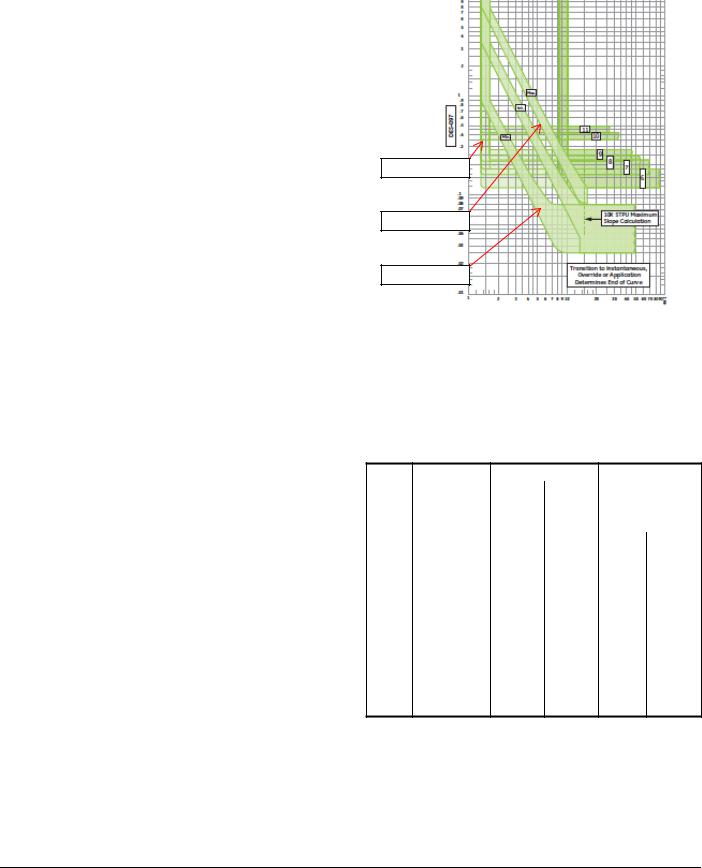
EntelliGuard TU Trip Units: UL/ANSI Models |
DEH-4567B |
Protection |
|
Table 2-3: Short Time Commit Times
|
60 Hz |
50 Hz |
Time Band |
ANSI, UL489 |
ANSI, UL489 |
1 |
0.025 sec |
0.030 sec |
2 |
0.033 sec |
0.040 sec |
3 |
0.042 sec |
0.050 sec |
4 |
0.058 sec |
0.060 sec |
5 |
0.092 sec |
0.090 sec |
6 |
0.117 sec |
0.120 sec |
7 |
0.158 sec |
0.160 sec |
8 |
0.183 sec |
0.180 sec |
9 |
0.217 sec |
0.220 sec |
10 |
0.350 sec |
0.350 sec |
11 |
0.417 sec |
0.420 sec |
12 |
0.517 sec |
0.520 sec |
13 |
0.617 sec |
0.620 sec |
14 |
0.717 sec |
0.720 sec |
15 |
0.817 sec |
0.820 sec |
16 |
0.917 sec |
0.920 sec |
17 |
0.933 sec |
0.940 sec |
Table 2-4: Short Time Settings by Breaker Type and Frame
Breaker |
Available Settings |
Power Break I, Power |
OFF, 1.5 to 9, steps of 0.5 |
Break II, WavePro, AKR |
|
conversion kits |
|
AKR and WavePro 5000A |
OFF, 1.5 to 7, steps of 0.5 |
frame |
|
EntelliGuard G Frame 1 |
OFF, 1.5 to 12, steps of 0.5 |
and 2 |
|
EntelliGuard G Frame 3 |
OFF, 1.5 to 10, steps of 0.5 |
Short Time Delay
The Short Time Delay setting consists of both a slope setting and a fixed delay band setting. The slope and delay are independently selectable. The slope setting consists of three I2T slopes (minimum (1), intermediate (2) and maximum (3)) and fixed delay. The fixed delay bands consist of 11 constant time bands. The width of the bands varies by circuit breaker and with frequency. See Table 2-4.
On all ANSI and IEC breakers, the Short Time can be disabled by setting the Short Time Delay to “OFF”. Note that if Instantaneous is set to “OFF” Short Time cannot be turned off.
Figure 2-4: Short Time Delay
Slope OFF
Slope = 3
Slope = 1
Short Time Slope
The slope setting modifies the initial portion of the ST delay band in the familiar “hockey stick” configuration. A setting of OFF puts the constant time band in effect, with no slope. Slope settings of 1, 2, or 3 put progressively higher slope values in effect. If the fault exceeds the sloped section of the curve, the constant time band setting takes effect.
Table 2-5: Short Time Delay Settings
Band |
Time Delay |
Commit Time |
EntelliGuard G |
||
|
Band Setting |
50 Hz |
60 Hz |
Clear |
Clear |
|
|
|
|
Time |
Time |
|
|
|
|
60 Hz |
50 Hz |
1 |
Min. |
0.030 |
0.025 |
0.080 |
0.085 |
2 |
2nd |
0.040 |
0.033 |
0.088 |
0.093 |
3 |
3rd |
0.050 |
0.042 |
0.097 |
0.102 |
4 |
4th |
0.060 |
0.058 |
0.113 |
0.118 |
5 |
5th |
0.110 |
0.092 |
0.147 |
0.152 |
6 |
6th |
0.130 |
0.117 |
0.172 |
0.177 |
7 |
7th |
0.180 |
0.158 |
0.213 |
0.218 |
8 |
8th |
0.210 |
0.183 |
0.238 |
0.243 |
9 |
9th |
0.240 |
0.217 |
0.272 |
0.277 |
10 |
10th |
0.280 |
0.350 |
0.405 |
0.410 |
11 |
Max. |
0.340 |
0.417 |
0.472 |
0.477 |
•Short Time slope is forced to OFF when optional LT Fuse (i4t) curves are in use.
10 |
©2012 General Electric All Rights Reserved |
DEH-4567B |
EntelliGuard TU Trip Units: UL/ANSI Models |
|
Protection |
INSTANTANEOUS PROTECTION
Adjustable Selective Instantaneous over current protection causes an undelayed breaker trip when the chosen current level and proper waveform is reached.
The pickup value may be set in steps of 0.5 xIn from 2.0 xIn to 15 xIn and steps of 1 xIn from 15 xIn to a maximum of 30 xIn. Greater than 15xIn is available only in trips provided with the “Extended Range Instantaneous” option on ANSI EntelliGuard G circuit breakers.
The maximum possible setting depends on the trip unit instantaneous option provided, the circuit breaker’s withstand capability and whether or not ST has been enabled.
When Instantaneous pickup is set above 15X without ST on, ST pickup is automatically switched on Default delay is automatically switched on at a minimum delay setting, unless otherwise set by the user. This is only applicable to EntelliGuard G.
Table 2-6: Maximum Instantaneous for Power Break I, Power Break II, WavePro and AKR Trip Units
Frame |
ANSI (X In) |
UL (X In) |
||
(A) |
With ST |
W/O ST |
With ST |
W/O ST |
800 |
15 |
10 |
15 |
10 |
1,600 |
15 |
10 |
15 |
10 |
2,000 |
15 |
10 |
15 |
10 |
2,500 |
|
|
13 |
10 |
3,000 |
|
|
13 |
10 |
3,200 |
13 |
10 |
|
|
4000 |
9 |
9 |
9 |
9 |
5000 |
7 |
7 |
|
|
The Instantaneous pickup accuracy is +10%. On certain ANSI trip units with the user-selectable switchable instantaneous over current an additional value of OFF appears at the end of the listing of numerical values. Note that if Short Time Delay is set to off, you will not be able to also turn off Instantaneous.
When Instantaneous pickup is set above the maximum allowed for the CB without ST on, ST pickup is automatically switched on at a default delay is automatically switched on at a minimum delay setting.
WaveForm Recognition vs. Peak Sensing
WFR is the standard algorithm used in the normal instantaneous trip function for all CB versions except Power Break I. The WFR algorithm is specially designed to optimize selectivity while achieving fast instantaneous tripping of the circuit breaker. The algorithm’s measurements act as a proxy for measuring energy and hence are able to discern a fault current from a peak-let- through current allowed to flow by a current limiting fuse
or current limiting circuit breaker while interrupting in a current limiting manner. This allows the trip setting to be set much lower than optimally peak sensing trips and hence sensitive to lower arcing fault currents that could be causing an arc flash event.
Reduced Energy Let Through (RELT)
The EntelliGuard TU trip unit’s RELT capability provides the ultimate in user flexibility for wiring and controlling an alternate Instantaneous setting for temporary use to reduce personnel hazard.
All versions of the EntelliGuard TU trip units are available with Reduced Energy Let-Through (RELT) Instantaneous protection. This optional feature allows the trip unit’s Instantaneous Protection pickup threshold to be temporarily set lower when personnel are in close proximity to the circuit breaker. In the event of a fault, the trip unit will respond sooner, minimizing damaging arc flash energy. Once personnel are safely clear of the area, RELT is disengaged, returning the system to its normal Instantaneous settings. The RELT setting is independent of the normal adjustable selective Instantaneous. Even if the normal instantaneous is not enabled, by turning on RELT the instantaneous will then be enabled.
The pickup value may be set in steps of 0.5 xIn from 1.5 xIn to 15 xIn or the maximum allowed instantaneous pickup for the particular circuit breaker type, rating and size. The RELT Instantaneous pick up clears fault current in 50 milliseconds or less. The maximum setting depends on the trip unit catalog number, breaker type and frame, and whether or not ST is enabled. See Table 8.
Clearing times for the various instantaneous functions vary by circuit breaker. The RELT function clearing time is 0.042 seconds for EntelliGuard G at 60Hz and 0.05 seconds at 50Hz. The adjustable selective instantaneous is 0.05 and 0.06 seconds at 60 and 50 Hertz respectively. For Power Break II, AKR, and WavePro circuit breakers the clearing times are 0.05 and 0.058 seconds for RELT and selective instantaneous respectively at 60 Hz. Power Break does not offer the selective Adjustable Instantaneous or RELT function. Instantaneous clears in 0.05 seconds for Power Break versions of the EntelliGuard TU trip unit.
When the RELT option is configured in an EntelliGuard TU Trip Unit Digital Input 1 and Digital Output 1 are automatically and permanently configured to function with RELT. RELT is a factory installed option—it cannot be “turned on” if it is not purchased as an option. The Digital Output will be energized whenever RELT protection is engaged. The Digital Input can be wired to one or more external contacts, such as a light curtain, to engage RELT when someone is within range of the equipment.
©2012 General Electric All Rights Reserved |
11 |

EntelliGuard TU Trip Units: UL/ANSI Models |
DEH-4567B |
Protection |
|
RELT can also be controlled remotely over Modbus Communications. RELT Status is also provided via Modbus register. Separate Modbus commands are required to engage and disengage RELT.
Whenever RELT is engaged the trip unit’s LCD display will flash an obvious “RELT ON” warning.
Once engaged, all trigger sources (remote via Modbus and externally wired digital input) must be cleared before RELT will disengage. RELT will stay engaged for 15 seconds after the last trigger is cleared to give personnel time to clear the area.
Due to Lock-Out-Tag-Out (LOTO), RELT cannot be turned on or off from the trip unit LCD.
RELT capability may be provided on a trip unit with or without 24VDC control power.
When 24 VDC/AC is provided to the RELT input (input 1), the trip unit will use the set RELT Instantaneous trip setting.
NOTICE
Without control power connected to the trip unit permanently, indication that the trip unit is in the RELT mode may not appear on the main screen. The trip unit must be permanently connected to 24VDC control power for reliable communication regarding RELT status.
A RELT Switch Kit (catalog #GTURSK) can also be purchased to add a RELT switch to existing breakers. The kit includes the selector switch, LED bulb, NO/NC contacts, 8 feet of wire with spade connectors. The LED Bulb burden is 0.84 watts and the color of the switch is blue.
Table 2-7: Instantaneous Thresholds for Power Break I, Power Break II, WavePro and AKR Trip Units
Breaker |
Instantaneous |
Instantaneous |
Frame Size |
Threshold with |
Threshold without |
(A) |
Short Time (× IN) |
Short Time (× IN) |
800 |
Off, 2 to 15 |
Off, 2 to 10 |
1600 |
Off, 2 to 15 |
Off, 2 to 10 |
2000 |
Off, 2 to 15 |
Off, 2 to 10 |
3200 |
Off, 2 to 13 |
Off, 2 to 10 |
4000 |
Off, 2 to 9 |
Off, 2 to 9 |
5000 |
Off, 2 to 7 |
Off, 2 to 7 |
•RELT instantaneous allows the minimum threshold to go to 1.5X.
GROUND FAULT PROTECTION
The Trip Unit provides two types of ground fault protection: Ground Fault Summation and Ground Fault CT. These protections are independent. A related GF alarm function is available for both types of GF protection, and share the same pickup level, band choices and tolerances as the GF trip functions. If both Ground Fault Summation and Ground
Fault CT are desired, order both from the factory because after delivery these options cannot be changed.
Ground Fault Summation
This protection element operates continuously on the four current sensor inputs to the trip unit. On four pole breakers, the fourth pole is built into the circuit breaker. On 3 pole breakers the 4th pole is connected to a neutral sensor typically mounted in the cable section via the secondary disconnect. In applications that do not require a neutral sensor, this 4th pole connection must be shorted at the secondary disconnect to avoid nuisance tripping due to extraneous noise pickup.
NOTICE
POWERBREAK, AK, AKR, WAVEPRO AND CONVERSION KITS:
Ground Fault Sum is used for single source and multiple source Ground Fault schemes.
ENTELLIGUARD G
GF Sum is used for single source ground fault only. For multiple source ground fault see “Ground Fault CT,” below.
Ground Fault CT
This protection element is available only on the EntelliGuard G. It is typically utilized for multi-source Ground Fault (MSGF) applications in ANSI/UL applications where sensor data must be shared among multiple trip units on systems with multiple sources connected in parallel. Contact your local sales office or the Burlington factory for details on GE’s recommended MSGF implementation. When GF CT is specified in a breaker, a special “interposing CT” is installed in the breaker that is wired between the breaker’s secondary disconnect and the trip unit’s CT inputs. The full scale output of this CT is 1.54mA at 100% of external sensor.
The GF pickup value tolerance band is 15% of the set point. The ground fault pickup settings are listed in Table 2-8 as multiples of xCT the current sensor rating, in steps of 0.01 xCT. The maximum GF pickup value is limited to 1200 A per UL standard.
Multiple Ground fault curves are also available: Definite time, l2t slope, l4t and a double break special selective ground fault with dual l2t slopes. The pickup in all is drawn with a 10% tolerance and the bands are drawn with a 15% current tolerance. In the case of the double break selective ground fault the first slope is 10% tolerance, the second is 15%. See DES-093A for ground fault curve shapes.
12 |
©2012 General Electric All Rights Reserved |

DEH-4567B |
EntelliGuard TU Trip Units: UL/ANSI Models |
|
Protection |
Table 2-8: Ground Fault Pickup Settings
Protection |
Sensor, ICT |
Ground Fault Pickup |
Type |
|
Threshold (× ICT) |
GF SUM |
150–2000 |
0.20–0.60 (max of 1200 |
GF SUM ALARM |
|
A) (increment of 0.01) |
GF CT |
|
with OFF as a selection |
GT CT ALARM |
|
when GF or GF Alarm |
|
|
Switchable is optioned. |
GF/ALARM |
2500-3200 |
0.20–0.37 (increment of |
Pickup |
|
0.01) with OFF as a |
|
|
selection when GF or GF |
|
|
Alarm Switchable is |
|
|
optioned. |
GF/ALARM |
4000 |
0.20–0.30 (increment of |
Pickup |
|
0.01 with OFF as a |
|
|
selection when GF or GF |
|
|
Alarm Switchable is |
|
|
optioned. |
GF/ALARM |
5000 |
0.20–0.24 (increment of |
Pickup |
|
0.01) with OFF as a |
|
|
selection when GF or GF |
|
|
Alarm Switchable is |
|
|
optioned. |
GF/ALARM |
6000 |
0.2 (1200 A) with OFF as |
Pickup |
|
a selection when GF or |
|
|
GF Alarm Switchable is |
|
|
optioned. |
Ground-Fault Delay |
|
|
This function sets the delay before the breaker trips when the ground-fault pickup current has been detected.
The Ground Fault Delay setting consists of a selection between two I2T slopes: an optional steeper fuse slope, and fixed delay only. One of fourteen fixed time bands is also selected. The fixed delay bands are listed in Table 2-9.
The Ground Fault Delay settings consist of two user settings. The Time Delay band and the Ground Fault protective function curve shape. The time delay bands consist of up to 14 definite time response bands. Table 2-8 lists the available time delay bands for the various circuit breakers. There are four ground fault protective functions shapes that may be selected. Definite time (OFF), l2t slope, l4t slope and a double break special selective ground fault with dual l2t slopes.
The Ground Fault Delay band may be set to off based on trip unit configuration. Note that “switchable Ground Fault” is not UL listed.
Table 2-9: Ground Fault Time Delay Bands, 50 Hz & 60 Hz
Time |
EntelliGuard G UL |
PB I, PB II, WavePro, |
|||
Band |
Commit Time (S) |
AKR Commit Time (S) |
|||
|
60 Hz |
50Hz |
60 Hz |
|
50Hz |
1 |
0.042 |
0.050 |
|
|
|
2 |
0.058 |
0.060 |
0.058 |
0.060 |
|
3 |
0.092 |
0.110 |
0.092 |
0.110 |
|
4 |
0.117 |
0.130 |
0.117 |
0.130 |
|
5 |
0.158 |
0.180 |
0.158 |
0.180 |
|
6 |
0.183 |
0.210 |
0.183 |
0.210 |
|
7 |
0.217 |
0.240 |
0.217 |
0.240 |
|
8 |
0.350 |
0.280 |
0.350 |
0.280 |
|
9 |
0.417 |
0.340 |
0.417 |
0.340 |
|
10 |
0.517 |
0.390 |
0.517 |
0.390 |
|
11 |
0.617 |
0.540 |
0.617 |
0.540 |
|
12 |
0.717 |
0.640 |
0.717 |
0.640 |
|
13 |
0.817 |
0.740 |
0.817 |
0.740 |
|
14 |
0.917 |
0.840 |
0.917 |
0.840 |
|
•Power Break I, Power Break II, WavePro and AKR time band width is 60 msec.
•EntelliGuard G 60 Hz time band width is 0.055 sec.
•EntelliGuard G 50 Hz time band width is 0.060 sec.
ALARMS
Ground Fault Alarms
The Ground Fault alarm DOES NOT issue a trip event. If tripping on ground fault is required order LSIG not LSIGA. Instead it can turn on a digital output if an output is configured for it. It will always turn on an indication in the Modbus register map. The output can be used to turn on a light or other signal but it WILL NOT GENERATE A TRIP EVENT.
All GTUs with a Ground Fault trip can also send a signal after the trip event that a GF occurred.
Current Alarm
The trip unit provides two current alarms. These alarms will trigger an alert when current consumption exceeds their setpoints. This is useful for implementing load shedding processes, and serves as an alert to impending Long Time pickup. The alert can be signaled either via communications or via digital output. The Current Alarms’ ON/OFF pickup settings are 0.5 to 1.0 xIn in steps of 0.05.
The trip unit does not allow the current alarm OFF setpoint to be set above the ON setpoint.
If the highest measured phase current goes above the Current Alarm ON setpoint and remains above the setpoint for more than 60 seconds the alarm will be triggered. If the current falls below the Current Alarm OFF setpoint for more than 60 seconds while the Current Alarm is active, the alarm condition will be cleared.
©2012 General Electric All Rights Reserved |
13 |
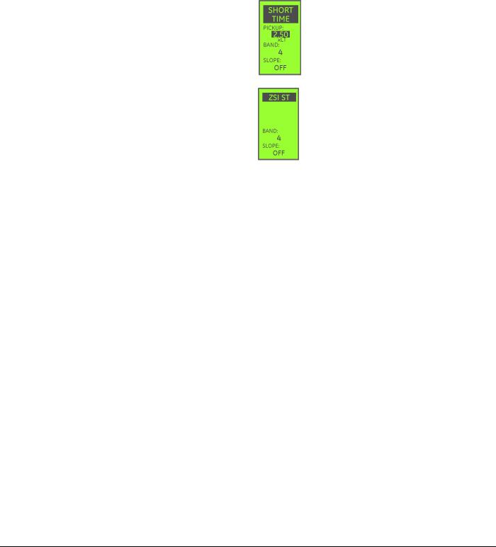
EntelliGuard TU Trip Units: UL/ANSI Models |
DEH-4567B |
Protection |
|
The serial register indicating the state of the Current Alarm will assume a value 1 when the alarm is triggered, and a value of zero if the alarm is cleared. If a digital output is mapped to the Current Alarm, it will be open if the alarm is clear, and closed if the Current Alarm is active. The alarm indications do not latch; they follow the state of the Current alarm.
ZONE SELECTIVE INTERLOCKING
Zone -selective interlocking coordinates breakers so that the downstream breaker is allowed the first opportunity to clear a fault or overload event.
The optional Zone Selective Interlocking (ZSI) function operates with a group of series-connected breakers. ZSI is achieved with the use of the TIM1 module or an equivalent GE qualified and recommended device.
There are two sets of settings in a breaker used in a Zone Selective Interlocking system. The normal or “unrestrained” setpoints are the main over current protection setpoints. A second set of ZSI or “restrained” setpoints are included for each interlocked protection element – GF, ST, and Instantaneous.
If a protection element, such as Ground Fault, goes into pickup and the Zone Selective Interlock input is active, the “restrained” or ZSI settings will be in effect. If the Zone Selective Interlock input is not active when the GF element
enters pickup, the normal or unrestrained GF pickup setpoints will be effect.
If the Zone Selective Input goes off while the restrained settings are in effect, they will remain in effect for 50 milliseconds. After that, the unrestrained settings will go into effect.
Unrestrained, normal mode ST setpoints: If the trip unit enters Short Time pickup and the ZSI input is OFF, these settings are in effect. In a ZSI configuration these settings are optimized for protection of the cable/bus directly below the breaker, and not for selectivity with downstream breakers.
Restrained settings: If the trip unit enters Short Time Pickup and the ZSI input is ON, these settings are in effect. This setting is intended to provide selectivity with the downstream breaker, so it will typically be set longer, to give the downstream breaker a chance to clear the fault.
14 |
©2012 General Electric All Rights Reserved |
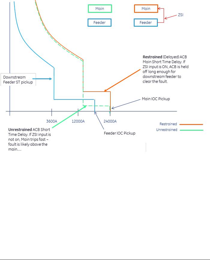
DEH-4567B |
EntelliGuard TU Trip Units: UL/ANSI Models |
|
Protection |
|
Figure 2-5: Restrained ZSI Settings |
ZSI Option
Two Zone- Selective-Interlocking options may be purchased with each trip. Option "Z" or option "T". Option Z allows the user access to short time or ground fault ZSI.
The user may enable or disable either or both. The "T" option adds Instantaneous ZSI capability. Instantaneous ZSI may be enabled or disabled by the user at any time.
Use of the short time or GF ZSI in a CB requires that the user set two different delay and slope bands for ground fault or short time depending on which he has enabled.
In Power Break II and Spectra MicroEntelliGuard Circuit Breakers the "T" option only enables instantaneous ZSI as an output to interlock with upstream circuit breakers such as a GE WavePro, AK, AKR, Conversion Kits or new EntelliGuard G (ANSI or UL489). The T option requires 24 VDC external power. The T option does not modify IOC
timing on PowerBreak I, PowerBreak II and Spectra MicroEntelliGuard circuit breakers.
The upstream breaker uses the ST ZSI and/or GF ZSI delay bands and slope, and/or transition to a delay Instantaneous if it receives a downstream ZSI signal.
The desired ZSI (ST and/or GF and/or Instantaneous) must be selected in order for the downstream breaker to issue a ZSI signal, and the upstream breaker to act upon this signal. If the ZSI setting is set to OFF no ZSI output signal is generated.
The ST ZSI Delay Bands are independent and have the same bands available. Slope settings may also be interlocked.
The GF ZSI Delay Bands are independent and have the same bands available. Slope settings may also be interlocked.
©2012 General Electric All Rights Reserved |
15 |

EntelliGuard TU Trip Units: UL/ANSI Models |
DEH-4567B |
Protection |
|
Instantaneous ZSI is either enabled or disabled. There are no settings to modify the action of Inst ZSI.
INST ZSI timing is as follows::
•EntelliGuard G (ANSI and UL489): An additional 2.5 cycles (ignore inst for 3 cycles after seeing input and trip on the 7th half cycle)
•AKR, WavePro and Conversion Kits: An additional 4 cycles (ignore inst for 4.5 cycles after seeing input and trip on the 9th half cycle.)
INTERRUPTION PROTECTION
Making Current Release (MCR)
Every EntelliGuard G circuit breaker uses a making current release. The making current release varies per circuit breaker Envelope and is related to the circuit breaker’s close and latch rating.
The MCR pickup is activated at the time the circuit breaker closes and for six cycles thereafter. When the six cycles are over, the threshold changes to the HSIOC pickup setting.
High Set Instantaneous Protection (HSIOC)
HSIOC is also known as Override Pickup. Some of the trip units on EntelliGuard G circuit breakers may be provided with an override instantaneous trip.
Whether such a trip is provided or not depends on the circuit breaker within which the trip is installed. If the circuit breaker’s withstand lcw is equal to the short circuit rating then the trip will not have an override pickup. If the withstand rating is lower than the short circuit rating then the trip will enable override protection of the circuit breaker at the short time withstand rating level.
In UL 489 circuit breakers the HSIOC setting is nominally at 107% of the Icw for the circuit breaker. Taking tolerance into account, the override’s minimum trip is at 100% of the circuit breaker’s Icw.
In UL 1066 (ANSI) circuit breakers the HSIOC setting is also at 107% Icw if the adjustable selective instantaneous is ON. If the adjustable selective instantaneous is OFF then the HSIOC nominal pick up is at 98% of the circuit breaker’s Icw and, considering tolerance, the minimum pickup is at 91% of the circuit breaker’s Icw.
Power Break I, WavePro and AKR circuit breakers do not employ an override function. Power Break II circuit breakers use a mechanical override function.
Breaker Interface Module (BIM)
The EntelliGuard G Breaker uses a Breaker Interface Module which is internally connected to the EntelliGuard G Trip Unit. This allows the breaker to electronically reject an incorrect trip unit being inserted into a breaker, instead of
the traditional mechanical rejection methodology used on other GE circuit breakers.
The BIM contains information that describes the breaker configuration to the trip unit. The trip unit extracts information on Sensor Rating, Interruption Rating, and pole configuration from the BIM. This is a one-time event that occurs when a new trip unit is first powered up in a breaker. Every time the trip unit powers up in the breaker from that point forward, it compares information in the BIM to the information it initially read and stored. If the information does not match the trip unit will immediately trip the breaker and set a BIM Error Flag, and record a BIM error trip event. In effect, the trip unit “marries” the breaker.
NOTICE
SOFTWARE REVISION 08.00.23 AND GREATER:
If a BIM read fails the trip unit will not open the breaker, instead it will modify its internal configuration to match the AIC rating of the least capable breaker in the family. The trip unit will periodically read the BIM after that, and on a successful match the original settings will be restored. While the BIM error persists a BIM Err message will be displayed on the LCD.
The “Universal Trip Unit” can be used as a replacement for any trip unit. The Protection and Advanced Features of the Universal trip unit should match the configuration of the trip unit being replaced to maintain the same functionality. The Universal trip unit is programmed with minimum values for all protection, and it will automatically read the BIM values from the first breaker it is installed in. This will force the Universal Trip Unit to assume the configuration of the trip unit it is replacing. Once this process is complete, the Universal Trip Unit cannot be moved to another breaker – it “marries” the breaker.
BIM Transaction Details
On power up the trip unit immediately queries the BIM for local breaker configuration information.
If the GTU’s internally stored BIM ID (Breaker Serial Number) is ZERO:
•Upon power-up the trip unit reads BIM ID
•Since there is no match:
o GTU uses Default Breaker Configuration Data for protection for approximately 200 msec
o GTU fetches BIM Data and uploads it into GTU non-volatile memory.
o GTU continues normal operation
16 |
©2012 General Electric All Rights Reserved |

DEH-4567B |
EntelliGuard TU Trip Units: UL/ANSI Models |
|
Protection |
If the GTU BIM ID (Breaker Serial Number) is NON-ZERO
•Upon power-up the trip unit reads BIM ID
•If there is no match:
o Breaker trips Note: Software Revision 08.00.23 and great, If a BIM read fails the trip unit will not trip the breaker, instead it will modify its internal configuration to match the AIC rating of the least capable breaker in the family. The trip unit will periodically read the BIM after that, and on a successful match the original settings will be restored. While the BIM error persists a BIM Err message will be displayed on the LCD.
o GTU shows BIM ID Mismatch Error
o GTU registers a BIM Trip Event
Under certain circumstances, it is possible to reconfigure a trip unit so that it can be installed in a different circuit breaker. This involves “divorcing” the BIM and trip unit so that the trip unit can be “married” to a different circuit breaker.
BIM Remarry Sequence:
1.Install the trip unit on the target breaker. On power up the breaker will be tripped due to BIM error.
2.BIM mismatch will be indicated.
3.Press Right + Left + Up simultaneously.
4.“BIM OK” will flash in the upper left corner of the LCD display if marry succeeded
5.“BIM ERROR” will show if the marry failed.
Upon execution of the procedure, GTU will upload the data if the breaker is open and the following data in the BIM matches the GTU data programmed in the factory:
•Sensor
•Standard (UL/ANSI/IEC)
•MCR
•HSIOC
•Breaker interruption rating (Frame)
If there is no match, BIM Data mismatch error will show. Otherwise, continue normal operation.
PROTECTIVE RELAYS
The protection relay can be set to cause either a trip or an alarm. If the PR Enable on the LCD is set to ON, a trip will be generated, if set to OFF an alarm will be generated. The alarms can provide external indication by using the digital output contacts. See “Output Relays,” below, about output contact behavior.
Voltage Unbalance
This function compares the highest or lowest phase voltage with the average of all three phases and initiates a trip if the difference exceeds the set point.
Table 2-10: Voltage Unbalance Settings
Item |
Option |
Voltage unbalance |
Adjustable from 10% to 50% |
pickup |
in increments of 1%. |
Voltage unbalance |
Adjustable from 1 sec to |
delay setting |
15 sec in increments of 1 sec. |
|
Setting this value to OFF |
|
disables this function. |
Current Unbalance |
|
This function compares the current in the highest or lowest phase with the average of all three phases and initiates a trip if the difference exceeds the set point.
Table 2-11: Current Unbalance Settings
Item |
Option |
Current unbalance |
Adjustable from 10% to 50% |
pickup |
in increments of 1%. |
Current unbalance |
Adjustable from 1 sec to |
delay setting |
15 sec in increments of 1 sec. |
|
Setting this value to OFF |
|
disables this function. |
Undervoltage Relay |
|
This function measures the voltage in all phases and initiates a trip if any phase voltage drops below the set point. This internal trip unit relay feature operates independently of any separately installed undervoltage Relay Accessory on the circuit breaker.
Table 2-12: Under Voltage Settings
Item |
|
Option |
Under voltage |
|
Adjustable from 50% to 90% in |
pickup |
|
increments of 1%. |
Under voltage |
|
Adjustable from 1 sec to 15 sec in |
delay setting: |
|
increments of 1 sec. Setting this value |
|
|
to OFF disables this function. |
Zero Voltage Trip |
|
|
“Trip on Zero Volts” is a setpoint that defines the operation of the UVR relay on a “dead bus”. It determines whether the protective relay UVR trip unit function trips or not when all three phase voltages drop to zero.
Overvoltage Relay
This function measures the voltage in all phases and initiates a trip if any phase voltage exceeds the setpoint. See Table 2-13.
©2012 General Electric All Rights Reserved |
17 |

EntelliGuard TU Trip Units: UL/ANSI Models |
DEH-4567B |
Protection |
|
Table 2-13: Over Voltage Settings
Item |
Option |
Over voltage |
Adjustable from 110% to 150% in |
pickup |
increments of 1%. |
Over voltage |
Adjustable from 1 sec to 15 sec in |
delay |
increments of 1 sec. Setting this value |
|
to OFF disables this function. |
Power Reversal Relay
This function measures the direction of power flow through the breaker and initiates a trip if a sufficient magnitude of reverse power is detected.
Table 2-14: Power Reversal Settings
Item |
Option |
Power reversal |
Adjustable from 10 kW to 990 kW in |
pickup |
increments of 10 kW. |
Power reversal |
Adjustable from 1 sec to 15 sec in |
delay |
increments of 1 sec. Setting this value |
|
to zero (0) will disable this function. |
Power Direction Setup
This function selects the normal power flow direction for the breaker. Set this parameter to match the direction of current flow through the breaker during normal operating conditions. This direction setup also affects the sign of the normal power metering displays.
Potential Transformer Voltage
Enter the primary voltage rating of the potential transformer. The range of values is 120 V to 600 V, with an increment of 1V. The voltage input coming into the trip unit must be wired into using voltage conditioners which steps the voltage down to an acceptable voltage level. See below for voltage conditioner plate wiring diagrams.
Figure 2-6: Voltage Conditioner Plate Wiring — Wye
18 |
©2012 General Electric All Rights Reserved |

DEH-4567B |
EntelliGuard TU Trip Units: UL/ANSI Models |
|
Protection |
|
Figure 2-7: Voltage Conditioner Plate Wiring — Delta |
NOTICE
An incorrect PT voltage set point will result in incorrect voltage and power metering values.
Potential Transformer Connection
Select the appropriate potential transformer connection, either line-to-line (Ph-Ph) or line-to-neutral (Ph-N). See “PT Connection,” below, for more details.
OUTPUT RELAYS
The number of outputs available varies by breaker. These are relay contact outputs to the secondary disconnect. Each output can be configured per Table 2-15.
The contacts are rated for 30 VDC/25 VAC max, 1 A.
Power Break I, Power Break II, WavePro, AK, AKR and Conversion Kit Trip Units have one output relay. EntelliGuard G Trip Units have two output relays. The relay output can be assigned to the following functions:
•Group 1 – GF Sum and GF CT alarm only. Does not latch.
•Group 2 – Overcurrent (LT, ST, IOC, GF, CT GF). Latches
•Group 3 – Protective Relay. Latches if trip.
•Group 4 – Current alarm 1
•Group 5 – Current Alarm 2
•Group 6 – Health Status
•Group 7 – RELT (Dedicated to Output 1 when optioned)
•Group 8 – GF sum and GF CT Alarm and TRIP functions.
•Group 9 – REF (restricted earth fault) trip ( IEC applications only)
•Group 10 – SEF (standby earth fault) trip (IEC applications only)
•Group 11 – UEF (unrestricted earth fault) trip (IEC applications only)
The trip units must have the specific option (as an example protective relay must be enabled in order for protective function to actuate the relay) enabled in order to actuate the relay.
Fan/Command Close Control
EntelliGuard trip units include an output dedicated to controlling either an external breaker cooling fan (5000A WavePro and AKR breakers only) or a remote close accessory (EntelliGuard G breakers only). Breaker documentation provides wiring information.
For WavePro and AKR breakers, the trip unit automatically calculates cooling requirements and activates the fan control output to maintain the breaker’s operating temperature.
For EntelliGuard G breakers, the remote close command is available via Modbus command. Issuing command 111 will
©2012 General Electric All Rights Reserved |
19 |

EntelliGuard TU Trip Units: UL/ANSI Models |
DEH-4567B |
Protection |
|
operate the command close coil accessory on the circuit breaker (remotely closes the breaker).
Table 2-15: Output Configuration
Group # |
Function |
Summary Description |
|
|
|
1 |
GF alarm |
Turns on when GF alarm is |
|
|
activated. |
2 |
Overcurrent |
Over-voltage trip turns ON the |
|
trip (GF, |
relay. |
|
INST, LT, ST) |
|
7 |
Reduced |
Output relay contact closes when |
|
Energy Let- |
the RELT pickup is enabled. |
|
Through |
|
|
(RELT) |
|
3 |
Protective |
When protective relay trips the |
|
relays |
relay contact closes. |
4 |
Current |
Exceeding current alarm pick-up |
|
alarm 1 |
turns closes the relay contact. |
5 |
Current |
Exceeding current alarm pick-up |
|
alarm 2 |
turns closes the relay contact. |
6 |
*Health |
Relay contact will be closed or |
|
status |
opened depending on the Health |
|
|
contact setting. (Either normally |
|
|
open (NO) or normally closed (NC) |
|
|
set via communication). |
BELL ALARM ACCESSORY
Bell Alarm with Lock-out Accessory Configuration Setup (applies to Power Break II and WavePro Trip Units only)
This defines the types of signals (protection trip, Shunt trip, Shunt Trip with Lockout, or Under Voltage Release trip) that activates the Bell Alarm-Alarm Only and Bell Alarm with Lockout accessories on the Power Break II breaker only. The customer may enable or disable a different path to activate these accessories from the different types of trip signals.
The following settings can be set on the LCD or through communication for PBII and WavePro breakers:
•Disabled
•Shunt Trip
•UVR Trip
•Over Current Trip
•Protective Relay Trip
•Shunt, UVR
•Shunt, Over Current
•Shunt, Protective Relay
•UVR, Over Current
•UVR, Protective Relay
•Over Current, Protective Relay
•Shunt Trip, UVR, Over Current
•Shunt, UVR, Protective Relay
•Shunt, Over Current, Protective Relay
•UVR, Over Current, Protective Relay
•Shunt, UVR, Over Current, Protective Relay
Settings Description
The following are descriptions of the effects of each accessory switch when it is enabled:
•If Bell Alarm or Bell Alarm with Lockout is set to Shunt Trip, an opening generated by a Shunt Trip will cause the Bell Alarm contacts to change state.
•If Bell Alarm with Lock-out is set to over current trip, a fault generated by LT, ST, GF, and/or Instantaneous will cause the Bell Alarm contacts to change state.
Bell Alarm Operation – EntelliGuard G breakers
The EntelliGuard G breaker has a mechanical lockout built into the breaker’s trip mechanism. The lockout actuator is always triggered when the flux shifter actuator “trips” the circuit breaker. The breaker’s mechanical lockout is not actuated if the breaker is “opened” using the front panel pushbuttons, or an optional shunt trip accessory.
There are two modes of operation for the Lockout button in UL & ANSI applications – MANUAL and AUTOMATIC. The trip unit’s Lockout button configuration is fixed based on the catalog number of the trip unit. MANUAL or AUTO operation is fixed at the factory, and cannot be changed. Do not attempt to rotate the knob as it will damage the locking mechanism.
In MANUAL mode the breaker’s lockout actuator is allowed to travel to its “triggered” position. As the lockout trigger extends from the breaker mechanism following a flux shifter operation, it pushes the knob on the front of the trip unit out. At this point the breaker mechanism is “locked out” and cannot be closed until the mechanical lockout is manually reset. Reset is accomplished by pushing in the button on the trip unit until the breaker lockout is reset.
In AUTOMATIC mode the breaker’s mechanical lockout actuator is physically restrained from traveling to its “triggered” position by the fixed knob on the trip unit. In other words, the mechanical lockout is fired when the flux shifter operates, but the trip unit’s knob “automatically resets” the lockout so that the breaker can be reclosed without manual intervention.
20 |
©2012 General Electric All Rights Reserved |
Loading...