


GE Consumer & Industrial
Electrical Distribution
BreakMaster™ Load
Interrupter Switch
Installation and Maintenance
imagination at work
BreakMaster Load Interrupter Switch
Overview
This instruction book is expressly intended to cover the installation, operation and maintenance of GE’s BreakMaster Load Interrupter Switch. This manual does not cover all possible contingencies, variations and details that may arise during installation, operation or maintenance of this equipment.
If the user has questions regarding a particular installation, contact the local GE sales office. For application information, consult your nearest GE sales office and refer to the appropriate ANSI standards.
Contents
|
Page |
Section 1 - Introduction |
2 |
1.0Basic Description and Application
1.1Switchgear Identification
1.2Safety Features
1.3Safe Practices
Section 2 - Receiving |
4 |
2.0Receiving
2.1Handling
2.2Storage
2.3Lifting Instructions
Section 3 |
- Feature Identification |
5 |
Section 4 |
- Installation |
6 |
4.0Joining BreakMaster Enclosures
4.1Connection of Switchgear to Transformer
4.2Bolting Torque Valves
4.3Electrical Clearances
4.4Grounding
4.5Medium Voltage Electrical Connections
4.6Connection to Metal Clad Switchgear Assembly
4.7Connection of Customer Power Cables
4.8Field Taping of Electrical Connections
4.9Securing Switchgear to Foundation
4.10Connection of Space Heaters to Customer’s Source
4.11Switch Inspection Before Startup
Section 5 - Operation |
13 |
5.0Mechanical Safety Interlocks
5.1Switch Operation
5.2Fuse Replacement Steps
5.3Shunt Trip Operating Guidelines
5.4Motor Operator
Section |
6 |
- Maintenance |
21 |
|
6.0 |
General Requirements |
|
||
Section |
7 |
- Selector Switch Configuration |
23 |
|
Section |
8 |
- Duplex Configuration |
23 |
|
Section |
9 |
- Auto Transfer Switchgear (LIS-ATS) Configuration |
24 |
|
Section |
10 |
- Troubleshooting |
26 |
|
Section |
11 |
- How to Contact GE |
27 |
|
11.0GE RESOLVE
11.1www.geelectrical.com
1

BreakMaster Load Interrupter Switch
Section 1 – Introduction
1.0Basic Description and Application
GE’s BreakMaster Load Interrupter Switch consists of an air insulated, three pole, gang-operated, quick-make, quick-break, load interrupter switch in a floor mounted metal enclosure. It can be applied with power fuses and many other protective devices to provide safe, economical switching and circuit protection where infrequent disconnecting means is required. The BreakMaster is designed for medium voltage circuit applications ranging from 2.4kV through 15kV in 600 or 1200 load ampere interrupting ratings. The switch is operated externally from the front of the cubicle and is equipped with a quick make, quick break mechanism to open and close the switch independent of the speed with which the operating handle is moved, manually or power operated. The switchgear meets or exceeds all applicable ANSI, NEMA and IEEE standards and the Seismic requirements of the UBC zone 4 and CBC zone 4 building codes and UL listed switches are available as an option.
1.1Switchgear Identification
A data nameplate is located beneath the switch operating handle of each BreakMaster vertical switch section (see Figure 1). Contained on this nameplate are the GE order number, serial number, drawing number, and switch style number. This information should be given to the GE sales office if a question should arise concerning the switchgear or if renewal parts are required. These numbers allow the factory to completely identify the switchgear. Also located on the nameplate are voltage and current ratings for the switch and switchgear.
1.2Safety Features
GE’s BreakMaster Load Interrupter Switch meets or exceeds all of the following standards:
Standards
|
C37.20.3 |
|
|
|
|
ANSI/IEEE |
C37.20.4 |
|
|
|
|
|
C37.22 |
|
|
|
|
NEMA |
SG-6 |
|
|
|
|
UL |
UL 1008A (LIS-ATS only) |
|
|
||
See ANSI standards |
||
|
||
|
|
|
CSA |
C22.2, No. 31 |
|
C22.2, No. 193 |
||
|
||
|
|
|
IEEE |
693-1997 |
|
|
|
GE’s BreakMaster Load Interrupter Switch has several built in features to reduce hazards and to provide proper operating sequences.
1.Door interlock prevents opening the enclosure front doors while the switch is in the closed position.
2.Switch interlock prevents manual operation of the handle mechanism with the doors open.
3.A viewing window is provided to verify each switch contact position.
4.Facilities are provided for padlocking the switch in the open or closed position.
5.Mechanical indicators show whether the switch mechanism is open or closed.
6.Key interlocks, when provided, force a sequence of operation.
! WARNING
Exceeding nameplate ratings of the switchgear could cause property damage, se ry, or death. Switchgear must be operated within its nameplate ratings.
Figure 1
|
|
BR |
|
ER LOAD |
|||
|
|
INTERRUPTER SWITCH |
|||||
|
RE |
|
|
|
XXXXXXX |
|
|
|
F |
ORY ORDER NO. |
|
|
|
||
|
|
XXXXXXXX |
|
|
|||
|
SWI |
RT NO. |
|
|
|
||
|
|
XXXXX-X |
|
|
|||
|
MANU |
DATE |
|
28-JUN-00 |
|
|
|
|
|
|
|
|
|
|
|
|
|
|
|
|
|
|
|
|
R |
|
VOLTAGE |
KV |
15 |
|
|
|
IMPULSE WITHSTAND (BIL) |
KV |
|
|
|
||
|
95 |
|
|
||||
|
NORM. FREQ. WITHSTAND |
KV |
|
|
|
||
|
36 |
|
|
||||
|
FREQUENCY |
|
HZ |
60 |
|
|
|
|
C |
|
|
A SYM |
|
|
|
|
|
|
600 |
|
|
||
|
LO |
|
|
A SYM |
|
|
|
|
|
|
600 |
|
|
||
|
MOMEN |
|
KA ASYM |
|
|
|
|
|
|
40 |
|
|
|||
|
SHO |
|
RRENT |
KA SYM |
25 |
|
|
|
|
– TIME |
|
SEC |
|
|
|
|
|
|
2 |
|
|
||
|
F |
T CLOSING CURRENT |
KA ASYM |
40 |
|
|
|
|
|
|
|
|
|
|
|
|
|
|
|
|
|
|
|
|
FUSE/RATING |
|
|
175 |
|
|
|
|
FUSE CATALOG NO. |
|
|
|
|||
|
|
9F62FDD175 |
|
|
|||
|
INTEG |
|
KA ASYM |
|
|
|
|
|
|
40 |
|
|
|||
|
SHO |
|
|
|
|
|
|
|
|
|
|
||||
|
MAIN BUS AMPACITY |
A |
N/A |
|
|
||
|
MAIN BUS BRACING |
KA ASYM |
|
|
|
||
|
50 |
|
|
||||
|
ENC |
|
C |
|
|
|
|
|
|
|
INDOOR |
|
|
||
|
|
|
|
|
|
|
|
|
|
|
im nation at work |
|
|
|
|
190B9965P1 |
|
ASSEMBLED IN MEXICO |
|||||
|
|
|
|
|
|
|
|
2

BreakMaster Load Interrupter Switch
1.3Safe Practices
Only qualified electrical workers with training and experience on high voltage circuits should be permitted to work on this equipment. They should be familiar with the work to be performed, the safety equipment required and hazards involved.
Read and understand these instructions before attempting any assembly, operation, or maintenance of this switchgear. Exceeding nameplate ratings of switchgear could cause property damage, severe injury, or death.
1.Make sure all power sources are disconnected before making any adjustments or performing maintenance.
2.After opening the switch and before opening the door, use viewing window to insure that all three switch blades are open. If necessary, use a flashlight to verify.
! WARNING
The |
re several interlocks on the switches. They are for personnel and/or |
|
equipment protection. Unde |
rcumstances should they be made |
|
inoperative when switch is in service. To do so could cause bodily injury or property damage.
3.Never energize the switch without the arc chutes and barriers installed.
4.Always be sure that all hardware is in place and bolted tightly before putting switch into operation.
5.Before replacing covers, carefully inspect buswork and phase barriers to insure that no tools or other objects are accidentally left inside the unit.
N
Any work done on this equipment must conform to the appropriate OSHA and
NF
3
BreakMaster Load Interrupter Switch
Section 2 – Receiving
2.0Receiving
A visual inspection – inside and out – should be performed immediately upon receipt of the switchgear and before removing it from the truck. Shipping papers should be checked to ensure all boxes or other accompanying pieces have been received. If any damage or shortages are evident, a claim should be filed at once with the carrier and the nearest GE sales office.
The data nameplate for each switch assembly is located beneath the switch operating handle. The order number, serial number, and drawing number are located on this nameplate and should be given to the GE representative whenever identification of the assembly is required.
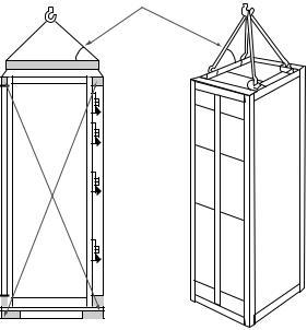
2.1Handling
Removable lifting plates are provided on the top of the BreakMaster structure for insertion of hooks to lift the complete structure. This is the only recommended method of moving the BreakMaster structure. Extreme care should be used not to damage or deform the unit if other moving methods are employed.
2.2Storage
If it is necessary to store the equipment before installation, keep it in a clean, dry location with ample air circulation and heat to prevent condensation. Like all electrical apparatus, these units contain insulation that must be protected against dirt and moisture. OUTDOOR UNITS MAY BE STORED OUTSIDE ONLY IF ROOF CAPS ARE
INSTALLED, SPACE HEATERS ENERGIZED AND ANY OPENINGS ARE COVERED.
2.3Lifting Instructions
1.Do not pass cables or ropes through support holes.
2.Always use load rated shackles or safety hooks in support holes.
3.Rig so that legs of sling (Figures 2 and 3) are no less than 45 degrees from horizontal.
NOTE:
Figure 2 – Using lifting slings, spreader and blocking which are not furnished with equipment.
Figure 3 – Using lifting plates, angles or beams which are furnished with equipment.
Figures 2 and 3
45 Degrees Minimum
4

BreakMaster Load Interrupter Switch
Section 3 – Feature Identification
3.0 |
Front View with Top Door Open |
3.1 |
Front View with Lower Door Open |
|
|
Louvers – |
Switch |
Louvers – |
Oversize |
|
Front and |
|||
|
Front and |
Mechanism |
||
|
Inspection |
|||
|
Rear |
|||
|
Rear |
|
||
|
|
Window |
||
|
|
|
||
|
|
|
|
|
|
|
Safety Mechanical |
|
|
|
|
Interlock |
Highly Visible |
|
|
|
|
Safety Mechanical |
|
|
|
|
Warning SIgn |
|
|
|
|
Interlock |
|
|
|
Key Interlock |
|
|
|
|
|
|
|
|
|
(when required) |
|
|
|
|
|
|
Data Label |
|
Oversize |
Data Label |
|
|
|
Inspection |
|
|
|
|
Window |
|
Lower |
|
|
|
|
|
|
|
|
|
Door |
|
|
Top Door |
|
|
|
|
|
|
|
Lower Fuse |
|
|
|
|
Compartment |
|
|
Tough Polyester |
|
|
|
All Covers 11 Gauge Steel |
Paint 2-mil Baked |
|
Ground Bus |
|
|
Coating Thickness |
|
|
3.2Side View with Covers Removed
Lifting Angles Provided on All Sections
|
Copper Bus Standard |
|
Switch Mechanism |
Glass Polyester |
|
Insulators |
Heavy-duty |
Porcelain Available |
|
as an option |
Chain Drive |
Full Height |
|
Phase Barrier |
|
Large Cable |
|
Pulling Space |
|
Ground Bus |
|
|
Rigid Bolted Frame |
|
Construction |
5

BreakMaster Load Interrupter Switch
Section 4 – Installation
4.0Joining BreakMaster Enclosures
4.0.0Access to BreakMaster Vertical Sections Containing Switches
Each BreakMaster load interrupter switch is shipped from the factory in the closed position to maintain alignment during shipping and handling. The safety interlocking prevents opening of the door of the vertical section when the switch is closed. In order to gain access to the interior, be sure the switchgear is on a true and level surface. To open a manually operated BreakMaster switch, pull the release button and rotate the handle to the open position.
When handling the BreakMaster enclosure and moving switches, be sure the switches are in the closed position. Do not operate switches unless they are setting on true and level surfaces.
4.0.1Identification of Shipping Splits
Refer to the front view drawing. Below this drawing, shipping splits will be identified in relation to group numbers for each cubicle. Normally shipping sections will not exceed 90 inches in width.
4.0.2Procedures for Joining BreakMaster Enclosures at Shipping Splits
The joining of sections consists of 2 bolted connections on the top and bottom of each depth frame member. In addition, 2 bolted connections are made on each vertical frame member. The vertical connections are located 1⁄3 and 2⁄3 up from the bottom of the BreakMaster Load Interrupter Switch (if 90” high switch, then connections are made at 30” and 60” off the ground).
Make any main and ground bus connections using splice plates and hardware furnished. Bus bars are usually tin or silver plated. To insure a proper electrical connection, care should be taken to protect the plating from damage. DO NOT use joint compound.
! WARNING
Wipe surfaces with clean, dry cloth to clean.
Cleaning bus joints with abrasive or chemical cleansers may
rve plating, which may cause joint overheating.
4.1Connection of Switchgear to Transformer
4.1.1Indoor Assemblies
Holes are pre-drilled in the side of the BreakMaster structure to match holes provided in the transformer.
4.1.2Outdoor Throat Connection
a.Switch and transformer should be brought together to give spacing of 1⁄2 inch between throat flanges.
b.Apply double bead of caulking material supplied with Breakmaster switchgear to outside surfaces of both flanges.
c.Move switch and transformer together to compress caulking material.
6

BreakMaster Load Interrupter Switch
4.2Bolting Torque Values
BreakMaster Load Interrupter switches are furnished with medium carbon steel hardware having a high tensile strength of 120,000 psi. SAE 5 or better hardware should be used for any additional bolting. The use of a torque wrench is recommended to assure the following torques. These torques apply to aluminum or copper connections. When torquing bolts the following values are nominal:
1⁄4” bolts – 4 lb. ft.
5⁄16” bolts – 9 lb. ft.
3⁄8” bolts – 16 lb. ft.
1⁄2” bolts – 39 lb. ft.
5⁄8” bolts – 80 lb. ft.
Flat washers and lock washers should be used for all connections. Washers should not be included under the heads of carriage bolts.
4.3Electrical Clearances
The following minimum clearances should be maintained after field modifications:
|
2.4 kV - 5kV |
7.2 kV - 15kV |
Between live parts of adjacent phases: |
|
|
Through air: |
3 1⁄2” |
5 3⁄4” |
Over Surface: |
3 1⁄2” |
5 3⁄4” |
Between live parts and grounded |
|
|
metal through air over surface: |
3 1⁄2” |
5 3⁄4” |
4.4Grounding
The ground bus is bolted to the uprights of the frame structure. It is arranged so that connections to the station ground can be made in any unit. A ground bus is included in each section for connecting the BreakMaster equipment to the station ground.
! WARNING
It is very important that the equipment be adequately grounded to insure that all
pa |
ve parts, need to be at ground potential. |
4.5Medium Voltage Electrical Connections
4.5.1Connection by Cable Supplied with BreakMaster Switch
a.Cables are not factory pre-cut to proper length. Installer must cut to fit.
b.Since factory cables are unshielded, they must be properly separated from each other, from all grounded metal parts, and from transformer bushing/terminals of other phases.
c.BreakMaster conforms to ANSI standards concerning phasing. Phases are arranged A, B, C, front to rear, top to bottom, and left to right at connection points unless otherwise noted on the drawings. The installer is responsible for maintaining continuity of phasing throughout the system.
d.Lugs are provided with the switchgear for terminating cable to the transformer bushings/terminals.
4.5.2Connection by Bus Bar
a.Flexible bus straps or splice plates and hardware are furnished with the BreakMaster Load Interrupter Switch.
b.Copper bus bar is tin or silver plated.
7
BreakMaster Load Interrupter Switch
4.6Connections to Metal Clad Switchgear Assembly
4.6.1Indoor Switchgear
Holes are predrilled in the side of the BreakMaster Load Interrupter Switch structure to match holes provided in Metal Clad switchgear. Bolt together using hardware furnished with BreakMaster Load Interrupter Switch.
4.6.2Outdoor Switchgear
a.Position units side by side. Holes in BreakMaster switch side sheet around bus cutout will match holes in metal clad switchgear flange.
b.Press weather stripping putty on to flange for weather-tight seal.
c.Join enclosures using bolts supplied with BreakMaster switch. Opposite side of metal clad switchgear flange has nuts welded in place for ease of connection.
4.7Connection of Customer Power Cables
Cable termination space is provided in the cubicle for top or bottom cable entry as shown on the outline drawings. Adequate electrical clearance must be maintained between cables, energized parts, and grounded metal parts. It is also the installer’s responsibility to adequately support cables such that insulators or bus bars do not carry the strain of the cables.
Tin-plated aluminum clamp type terminals are suitable for acceptance of copper or aluminum cable. If potheads or other special terminations are supplied, termination should be made according to the terminator manufacturer’s instructions.
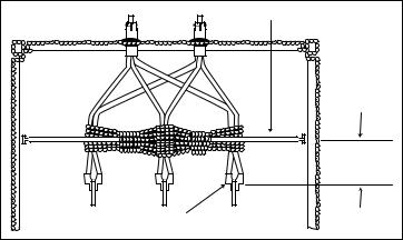
4.7.1Installation Procedure for Main Cables when Cable Brace is Provided
Align conduit holes in a linear orientation directly over or as close as possible to the braces. Consideration should be given to installing conduits or sleeves which might be required for future connections.
Run and bend the main cable in a most convenient orientation, making sure the main cable has been located directly up against the cable braces before it connects to the main cable terminals. Lash the main cable according to Figure 4 above, using a 3/8” nominal nylon rope, or a polyester braided rope having a tensile strength of 2000 lbs. minimum, making 6 revolutions around the “A” and “B” phase main cables and 6 revolutions around the “B” and “C” phase main cables. Continue wrapping the cord around the main cable lashing and around the cable braces (if applicable), in between the phases, tying a knot to the cable brace or cable as you complete your last revolution. All revolutions should be made as tight as possible so as to prevent whipping during short circuits. The nylon rope is not provided.
Figure 4
Cable Brace |
6" |
Maximum |
Main Cable Terminals |
8
 Loading...