


 Loading...
Galaxy Power System 4812/24 (GPS 4812/24)
H569-436
User’s Guide
Select Code 167-792-161
Comcode 108313057
Issue 9
Januray 2008
User’s Guide
Select Code 167-792-161
Comcode 108313057
Issue 9
Januray 2008
Galaxy Power System 4812/24 (GPS 4812/24)
H569-436
Notice:
The information, specifications, and procedures in this manual are subject to change without notice. Lineage Power assumes no responsibility for any errors that may appear in this document.
© 2008 Lineage Power
All International Rights Reserved
Printed in U.S.A.

Galaxy Power System 4812/24
Table of Contents
1 Introduction |
|
GPS 4812/24 |
1-1 |
Overview |
1-1 |
Illustrations |
1-1 |
Customer Service Contacts |
1-4 |
Customer Service, Technical Support, Product Repair and |
|
Return, and Warranty Service |
1-4 |
Customer Training |
1-4 |
Downloads and Software |
1-4 |
2 System Description |
|
Overview |
2-1 |
Block Diagram |
2-1 |
System Components |
2-2 |
Architecture |
2-3 |
Configurations |
2-3 |
Illustrations |
2-3 |
3 |
Galaxy Controllers |
|
|
Overview |
3-1 |
|
Introduction |
3-1 |
|
Galaxy Millennium Controller |
3-2 |
|
Design |
3-2 |
|
User Interface and Display |
3-2 |
|
Default Display |
3-2 |
|
LEDs |
3-3 |
|
Test Jacks |
3-3 |
|
Pushbutton Keys |
3-4 |
|
Access Panel |
3-4 |
|
Galaxy Vector Controller |
3-5 |
|
Design |
3-5 |
|
User Interface and Display |
3-5 |
|
Default Display |
3-5 |
|
LEDs |
3-5 |
|
Pushbutton Keys |
3-6 |
|
Access Panel |
3-6 |
|
Reference Material |
3-7 |
|
Controller Product Manuals |
3-7 |
|
RPM System Product Manual |
3-7 |
Issue 9 Januray 2008 |
Table of Contents - 1 |

Galaxy Power System 4812/24
4 Rectifiers |
|
596 Series A and D |
4-1 |
Overview |
4-1 |
Front Panel Display |
4-1 |
Power Switch |
4-1 |
Status Indicators |
4-1 |
Current Display |
4-2 |
Lamp Test |
4-2 |
Features |
4-3 |
Output Current “Walk-in” |
4-3 |
Output Protection |
4-3 |
Electronic Current Limit |
4-3 |
High Voltage Shutdown (HVSD) |
4-3 |
Restart |
4-3 |
Fan Alarm and Control |
4-3 |
Thermal Alarm |
4-3 |
Autonomous Operation |
4-3 |
Controller Communications Alarm |
4-3 |
Connectorized |
4-4 |
“Forced” Load Sharing |
4-4 |
5 AC Input Panels |
|
Overview |
5-1 |
AC Service |
5-1 |
Illustrations |
5-1 |
6 Battery Connection Panels |
|
Overview |
6-1 |
Function |
6-1 |
Illustrations |
6-1 |
7 DC Distribution Panels
Overview |
7-1 |
Function |
7-1 |
Illustrations |
7-1 |
2 - Table of Contents |
Issue 9 Januray 2008 |

Galaxy Power System 4812/24
8 |
Circuit Boards |
|
|
Overview |
8-1 |
|
Function |
8-1 |
|
Terminal Boards |
8-1 |
|
Alarm Boards |
8-1 |
|
Alarm/Terminal Boards |
8-1 |
|
BLJ Terminal Board |
8-1 |
|
Overview, continued |
8-2 |
|
Contactor Control Board |
8-2 |
|
Millennium Systems |
8-2 |
|
Vector Systems |
8-2 |
9 Specifications
GPS 4812/24 |
9-1 |
Rectifier |
9-3 |
AC Input Panels |
9-5 |
Applications and Cross Reference |
9-5 |
Battery Connection Panels |
9-6 |
DC Distribution Panels |
9-7 |
10Safety
11Maintenance and Replacement
Requirements |
11-1 |
System |
11-1 |
Batteries |
11-1 |
Rectifiers |
11-1 |
Rectifier Fan Assembly |
11-2 |
Replacement Procedures |
11-3 |
Installing or Replacing a Rectifier |
11-3 |
Replacing a Rectifier Fan Assembly |
11-5 |
Replacement Parts |
11-6 |
System |
11-6 |
Millennium Controller Circuit Boards |
11-7 |
Vector Controller Circuit Boards |
11-7 |
Additional Ordering Information |
11-8 |
Documentation |
11-8 |
Software |
11-8 |
Issue 9 Januray 2008 |
Table of Contents - 3 |

Galaxy Power System 4812/24
12 Troubleshooting Preparations |
|
Preliminary |
12-1 |
Introduction |
12-1 |
Safety |
12-1 |
Tools |
12-1 |
Troubleshooting Procedure |
12-2 |
Purpose |
12-2 |
Cabinet Alarm |
12-2 |
System Status |
12-3 |
Alarms Menu |
12-3 |
Troubleshooting Tables |
12-4 |
Identifying Problems |
12-5 |
Reference Figures |
12-6 |
Figure Numbers and Titles |
12-6 |
Millennium Controller |
12-7 |
Vector Controller |
12-9 |
Rectifiers |
12-10 |
Low Voltage Battery Disconnect |
12-11 |
AC Input |
12-12 |
DC Distribution |
12-13 |
Low Voltage Load Disconnect |
12-14 |
13 Troubleshooting Millennium Systems
Introduction |
13-1 |
In This Section |
13-1 |
Preparation |
13-1 |
Technical Assistance |
13-1 |
Troubleshooting Tables |
13-2 |
Organization |
13-2 |
Table Reference |
13-2 |
Millennium Display Reference |
13-2 |
AC System Alarm LED |
13-3 |
Battery Alarm LED |
13-4 |
Controller Alarm LED |
13-6 |
Distribution Alarm LED |
13-11 |
Rectifier Alarm LED |
13-12 |
Battery on Discharge and Remote Modules Alarm LEDs, |
|
or No LED |
13-16 |
4 - Table of Contents |
Issue 9 Januray 2008 |

Galaxy Power System 4812/24
14 |
Troubleshooting Vector Systems |
|
|
Introduction |
14-1 |
|
In This Section |
14-1 |
|
Preparation |
14-1 |
|
Technical Assistance |
14-1 |
|
Troubleshooting Tables |
14-2 |
|
Organization |
14-2 |
|
Table Reference |
14-2 |
|
Vector Display Reference |
14-3 |
|
AC Alarms |
14-4 |
|
Battery Alarms |
14-5 |
|
Controller Alarms |
14-6 |
|
Distribution Alarms |
14-7 |
|
Rectifier Related Alarms |
14-8 |
|
Miscellaneous Alarms |
14-11 |
15 |
Product Warranty |
|
Issue 9 Januray 2008 |
Table of Contents - 5 |
Galaxy Power System 4812/24
List of Figures
Figure 1-1: GPS 4812/24 Half Height Initial |
|
Cabinet (with Battery Stand) |
1-2 |
Figure 1-2: GPS 4812/24 Full Height Initial Cabinet |
1-3 |
Figure 2-1: Block Diagram of the GPS 4812/24 |
2-1 |
Figure 2-2: Schematic of Half Height Cabinet |
2-4 |
Figure 2-3: Schematic of Full Height Cabinet |
2-5 |
Figure 2-4: Schematic of Two-cabinet System Architecture |
2-6 |
Figure 2-5: Half Height GPS 4812/24 with Door Open |
2-7 |
Figure 2-6: Full Height GPS 4812/24 with Door Open |
2-8 |
Figure 3-1: Galaxy Millennium Controller Front Panel |
3-2 |
Figure 3-2: Galaxy Vector Controller Front Panel |
3-5 |
Figure 4-1: Rectifier Front Panel |
4-2 |
Figure 5-1: AC Input Circuit Breaker Panels |
5-2 |
Figure 5-1: AC Input Terminal Strip Panels |
5-3 |
Figure 6-1: H569-436 G30 (ED83143-31 G32) |
|
Battery Connection Panel |
6-2 |
Figure 6-2: H569-436 G31 (ED83143-31 G31) |
|
Battery Connection Panel |
6-2 |
Figure 6-3: H569-436 G34 (ED83143-31 G41) |
|
Battery Connection Panel |
6-3 |
Figure 6-4: H569-435 G35 (ED83143-31 G42) |
|
Battery Connection Panel |
6-3 |
Figure 6-5: H569-436 G36H (ED83143-31 G33) |
|
Battery Connection Panel |
6-4 |
Figure 6-6: H569-436 G37F/38F (ED83143-31 G60/61) |
|
Battery (OLE) Connection Panel |
6-4 |
Issue 9 Januray 2008 |
List of Figures - 1 |

Galaxy Power System 4812/24
Figure 6-7: H569-436 G80/81/82 (ED83143-31 G31/43) |
|
Battery Connection Panel |
6-5 |
Figure 6-8: H569-436 G84H (ED83143-31 G34) |
|
Battery Connection Panel |
6-6 |
Figure 6-9: H569-436 G85F (ED83143-31 G35) |
|
Battery Connection Panel |
6-6 |
Figure 6-10: H569-436 G86/87 (ED83143-31 G63/64) |
|
Battery Connection Panel |
6-7 |
Figure 7-1: H569-436 G40/50 (ED83143-31 G11) |
|
DC Distribution Panel |
7-2 |
Figure 7-2: H569-436 G41/51 (ED83143-31 G12) |
|
DC Distribution Panel |
7-2 |
Figure 7-3: H569-436 G42 (ED83143-31 G2) |
|
DC Distribution Panel |
7-3 |
Figure 7-4: H569-436 G43 (ED83143-31 G1) |
|
DC Distribution Panel |
7-3 |
Figure 7-5: H569-436 G44 (ED83143-31 G5) |
|
DC Distribution Panel |
7-4 |
Figure 7-6: H569-436 G46 (ED83143-31 G15) |
|
DC Distribution Panel |
7-4 |
Figure 7-7: H569-436 G52 (ED83143-31 G53) |
|
DC Distribution Panel |
7-5 |
Figure 7-8: H569-436 G53 (ED83143-31 G55) |
|
DC Distribution Panel |
7-5 |
Figure 7-9: H569-436 G60/61/65/66 (ED83143-31 G71) |
|
DC Distribution Panel |
7-6 |
Figure 7-10: H569-436 G67 (ED83143-31 G22) |
|
DC Distribution Panel |
7-6 |
Figure 7-11: H569-436 G68 (ED83143-31 G21) |
|
DC Distribution Panel |
7-7 |
Figure 9-1: Output Current vs. Temperature |
9-5 |
Figure 11-1: Detail of Rectifier Position |
11-3 |
Figure 12-1: Location of Cabinet Alarm |
12-2 |
2 - List of Figures |
Issue 9 Januray 2008 |

Galaxy Power System 4812/24
Figure 12-2: Millennium Controller Display |
12-8 |
Figure 12-3: Location of Millennium Controller Fuses |
|
and Boards |
12-8 |
Figure 12-4: Vector Controller Display |
12-9 |
Figure 12-5: Location of Vector Controller Fuses |
|
and Boards |
12-9 |
Figure 12-6: Rectifier Display |
12-10 |
Figure 12-7: Low Voltage Battery Disconnect Contactor |
|
Control Switches |
12-11 |
Figure 12-8: Detail of AC Input Panel and Rectifier Shelf |
12-12 |
Figure 12-9: Detail of DC Distribution Panel |
12-13 |
Figure 12-10: Low Voltage Load Disconnect Contactor |
|
Control Switches |
12-14 |
Issue 9 Januray 2008 |
List of Figures - 3 |

Galaxy Power System 4812/24
List of Tables
Table 9-A: Galaxy Power System 4812/24 Specifications |
9-1 |
Table 9-B: Rectifier Specifications |
9-3 |
Table 9-C: AC Input Panels |
9-5 |
Table 9-D: Battery Connection Panels |
9-6 |
Table 9-E: Battery Connection Panels |
9-7 |
Table 11-A: GPS 4812/24 System Replacement Parts |
11-6 |
Table 11-B: Galaxy Millennium Controller Circuit Boards |
11-7 |
Table 11-C: Galaxy Vector Controller |
|
Circuit Boards and Temperature Module |
11-7 |
Table 11-D: Product Documentation |
11-8 |
Table 13-A: AC Alarms |
13-3 |
Table 13-B: Battery Alarms |
13-4 |
Table 13-C: Controller Alarms |
13-6 |
Table 13-D: Distribution Alarms |
13-11 |
Table 13-E: Rectifier Related Alarms |
13-12 |
Table 13-F: Miscellaneous Alarms |
13-16 |
Table 14-A: AC Alarms |
14-4 |
Table 14-B: Battery Alarms |
14-5 |
Table 14-C: Controller Alarms |
14-6 |
Table 14-D: Distribution Alarms |
14-7 |
Table 14-E: Rectifier Related Alarms |
14-8 |
Table 14-F: Miscellaneous Alarms |
14-11 |
Issue 9 Januray 2008 |
List of Tables - 1 |

Galaxy Power System 4812/24
1 Introduction
GPS 4812/24
Overview |
Lineage Power developed the Galaxy Power System (GPS) 4812/24 to |
|
support -48 volt telecommunications powering solutions in worldwide |
|
markets. The GPS 4812/24 combines 55-ampere and 110-ampere, |
|
fan-cooled, switchmode rectifiers, microprocessor control technologies, |
|
battery and load disconnect/reconnect options, and a comprehensive |
|
line of fuse and circuit breaker dc distribution options in a modular |
|
front-access design. This modularity ensures easy access, simplified |
|
installation and maintenance, and allows the system to expand in |
|
capacity and features as power needs grow. |
|
With 7,040-ampere maximum capacity, distribution flexibility, and |
|
universal ac input capability, the GPS 4812/24 supports switching, |
|
transmission, and wireless applications in central office locations and |
|
environmentally controlled remote sites (huts or vaults). |
|
The main emphasis of this manual is to provide a general product |
|
description that will familiarize the user with the main components of |
|
the system and to provide guidelines for the basic maintenance of this |
|
Galaxy Power System. |
Note |
Prior to Issue 6 of this manual, the GPS 4812/24 cabinet had a metal |
|
door and the Galaxy Vector Controller consisted of a BIC3 board. For |
|
information on these systems, see Issue 5 of this manual. |
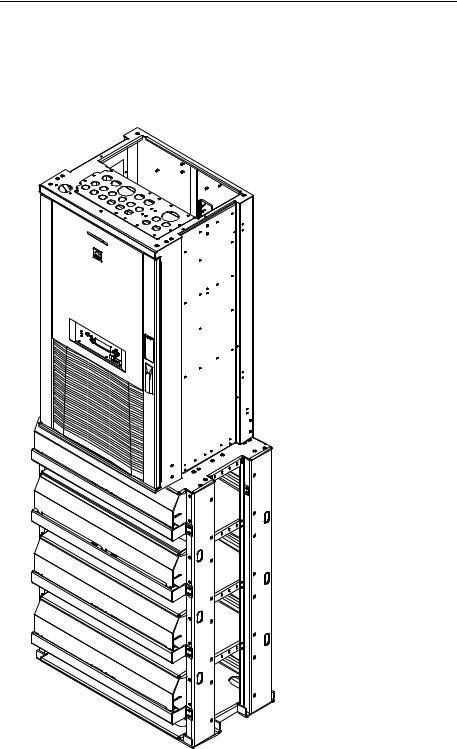
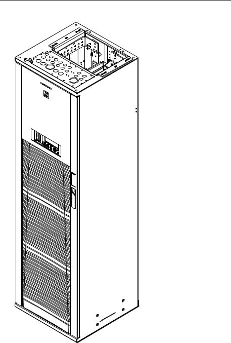
Illustrations |
Figures 1-1 and 1-2 illustrate the GPS 4812/24 half height and full |
|
height cabinets. |
Issue 9 Januray 2008 |
Introduction 1 - 1 |
Galaxy Power System 4812/24
Figure 1-1: GPS 4812/24 Half Height Initial Cabinet (with Battery Stand)
1 - 2 Introduction |
Issue 9 Januray 2008 |
Galaxy Power System 4812/24
Figure 1-2: GPS 4812/24 Full Height Initial Cabinet
Issue 9 Januray 2008 |
Introduction 1 - 3 |

Galaxy Power System 4812/24
Customer Service Contacts
Customer Service,
Technical Support,
Product Repair and
Return, and
Warranty Service
Customer Training
Downloads and
Software
For customers in the United States, Canada, Puerto Rico, and the US Virgin Islands, call 1-800-THE-1PWR (1-800-843-1797). This number is staffed from 7:00 am to 5:00 pm Central Time (zone 6), Monday through Friday, on normal business days. At other times this number is still available, but for emergencies only. Services provided through this contact include initiating the spare parts procurement process, ordering documents, product warranty administration, and providing other product and service information.
For other customers worldwide the 800 number may be accessed after first dialing the AT&T Direct country code for the country where the call is originating, or you may contact your local field support center or your sales representative to discuss your specific needs.
Lineage Power offers customer training on many Power Systems products. For information call 1-972-284-2163. This number is answered from 8:00 a.m. until 4:30 p.m., Central Time Zone (Zone 6), Monday through Friday.
To download the latest product information, product software and software upgrades, visit our web site at http://www.lineagepower.com
1 - 4 Introduction |
Issue 9 Januray 2008 |
Galaxy Power System 4812/24
2 |
System Description |
Overview
Block Diagram A basic block diagram of the Galaxy Power System 4812/24 is shown in Figure 2-1. It illustrates the arrangement and interconnections of the system components from the ac input to the dc output.
AC Input |
|
|
|
|
|
Power |
|
|
|
|
|
Chg |
Return |
DC Distribution |
|||
Bus |
|
|
|
|
|
(-) |
Bus |
LVLD |
|
|
|
|
(+) |
Control |
|
|
|
|
|
Board |
|
|
|
|
|
|
LVLD |
|
To 48 Volt |
AC Input |
|
|
|
|
Loads |
|
|
|
|
|
DISCHG RTN |
|
|
|
|
|
48V |
|
|
|
|
|
Returns |
|
|
Battery Distribution |
|||
|
|
|
|
|
BAT BUS |
|
|
LVBD |
|
|
|
|
|
Control |
|
|
Battery (-) |
|
|
Board |
|
|
|
Rectifiers |
|
|
|
|
|
|
|
Battery |
LVBD |
CHG RTN |
|
|
|
Shunt |
|
|
|
|
|
|
|
|
Battery (+) |
|
CO |
Sense/Control |
|
|
|
|
GND |
|
|
||
|
Connections |
|
Controller |
||
|
|
|
|||
|
|
|
|
||
Figure 2-1: Block Diagram of the GPS 4812/24
Issue 9 Januray 2008 |
System Description 2 - 1 |

Galaxy Power System 4812/24
Overview, continued
System |
The power system accepts alternating current from the commercial |
Components |
utility or a standby ac power source and rectifies it to produce dc power |
|
for the using equipment. The system’s control and alarm functions |
|
interact with the rectifiers and the office. In addition, the system |
|
provides overcurrent protection and charge, discharge, and distribution |
|
facilities. Battery reserve automatically provides a source of dc power if |
|
the commercial or standby ac fails. Battery reserve can be engineered to |
|
supply dc power for a specific period of time. In normal practice, battery |
|
capacity is sized to provide 3 to 8 hours of reserve time. |
|
AC Input connects the commercial and/or standby ac power sources to |
|
the rectifiers within the system and provides overcurrent protection. In |
|
some applications the ac service is wired directly to the rectifiers and |
|
overcurrent protection is provided at the service panel. |
|
Rectifiers convert an ac source voltage into the dc voltage level required |
|
to charge and float the batteries and to power the using equipment. |
|
Controller provides the local and remote control, monitoring, and |
|
diagnostic functions required to administer the power system. |
|
Batteries provide energy storage for an uninterrupted power feed to the |
|
using equipment during loss of ac input or rectifier failure. |
|
DC Distribution Panel provides overcurrent protection, connection |
|
points for the using equipment, and bus bars used to interconnect the |
|
rectifiers, batteries, and dc distribution. |
|
Battery Connection Panel provides connection points for the battery |
|
strings through battery disconnect fuses or contactors and current |
|
monitoring shunts. |
2 - 2 System Description |
Issue 9 Januray 2008 |
|
Galaxy Power System 4812/24 |
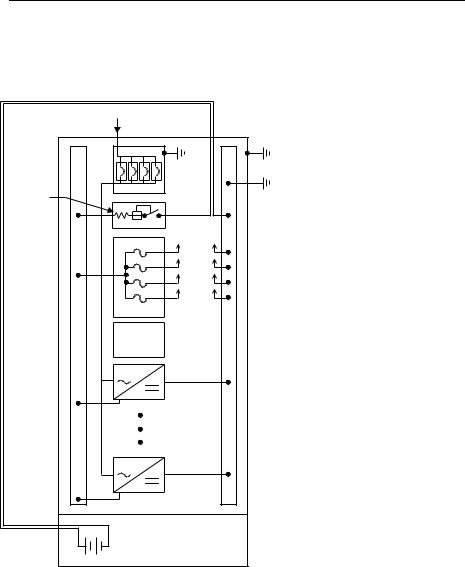
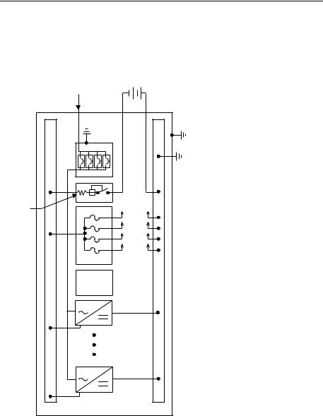
Architecture |
|
Configurations |
The GPS 4812/24 is available in two configurations: |
|
• The half height cabinet, shown in Figures 1-1 and 2-2, mounts on |
|
top of a battery stand and can provide up to 800 amperes of dc |
|
power. |
|
• The full height (7-foot) cabinet, shown in Figures 1-2 and 2-3, can |
|
provide up to 1,600 amperes of dc power. |
|
Each cabinet contains ac distribution, dc distribution panels, a battery |
|
connection panel, rectifiers, termination points for load circuits, and a |
|
system controller. |
Illustrations |
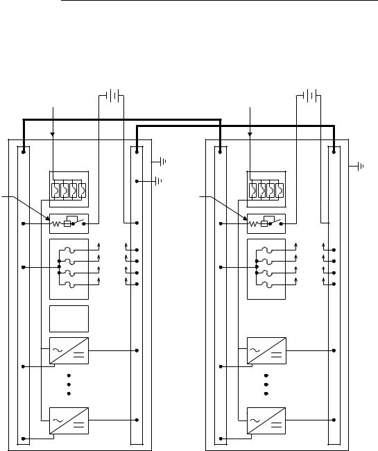
Figure 2-4 shows how supplemental full-height cabinets may be added |
|
to grow the system to 7,040 amperes. The rectifier output buses are |
|
interconnected to permit the cabinet to share current and ensure |
|
common voltage references for all system rectifiers. |
|
Figures 2-5 and 2-6 show open-door views of the half height and full |
|
height cabinets. |
Issue 9 Januray 2008 |
System Description 2 - 3 |
Galaxy Power System 4812/24
|
AC |
|
|
Cabinet |
|
|
Ground |
|
|
AC |
|
Battery |
Ground |
|
System (CO) |
||
Shunt |
||
Ground |
||
|
||
|
To Loads |
|
|
Control |
|
|
and |
|
|
Monitor |
|
|
Battery String(s) |
|
|
Mounted Below |
|
|
Half Height Cabinet |
Figure 2-2: Schematic of Half Height Cabinet
2 - 4 System Description |
Issue 9 Januray 2008 |
Galaxy Power System 4812/24
|
Battery |
|
|
String |
|
|
AC |
|
|
|
Cabinet |
|
AC |
Ground |
|
|
|
|
Ground |
|
|
|
System (CO) |
|
|
Ground |
Battery |
To Loads |
|
Shunt |
|
|
|
Control |
|
|
and |
|
|
Monitor |
|
Figure 2-3: Schematic of Full Height Cabinet
Issue 9 Januray 2008 |
System Description 2 - 5 |
Galaxy Power System 4812/24
Battery |
Battery |
String |
String |
AC |
AC |
Input |
Input |
Battery |
Battery |
Shunt |
Shunt |
To Loads |
To Loads |
Control |
|
and |
|
Monitor |
|
Initial Cabinet |
Supplemental Cabinet |
Figure 2-4: Schematic of Two-cabinet System Architecture
2 - 6 System Description |
Issue 9 Januray 2008 |
Galaxy Power System 4812/24
Controller Access Panel |
AC Panel |
|
(Circuit Breakers) |
||
|
LVBD
Control
Circuit
Miscellaneous
DC Distribution
Panels
LVLD
Control
Circuit
Rectifier
Shelves
596 Rectifier
Figure 2-5: Half Height GPS 4812/24 with Door Open
Issue 9 Januray 2008 |
System Description 2 - 7 |

Galaxy Power System 4812/24
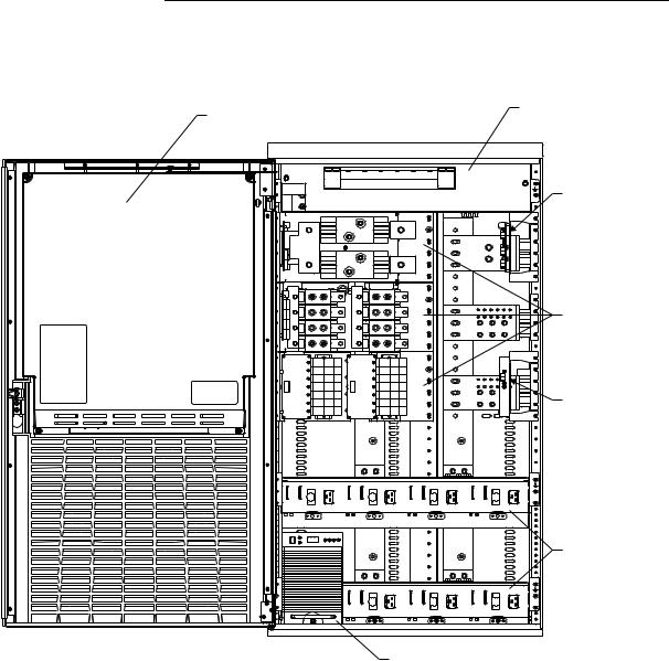
Controller Access Panel |
|
AC Panel |
|
|
(Terminal Strip) |
||
|
|
|
|
|
|
|
|
Low Voltage Battery
Disconnect Panel
Miscellaneous
DC Distribution
Panels
LVLD
Control
Circuit
Rectifier
Shelves
Figure 2-6: Full Height GPS 4812/24 with Door Open
2 - 8 System Description |
Issue 9 Januray 2008 |

Galaxy Power System 4812/24
3 |
Galaxy Controllers |
Overview
Introduction |
The GPS 4812/24 is available with either the Galaxy Millennium |
|
Controller or the Galaxy Vector Controller. |
|
This section describes the operation of each controller. It also provides |
|
detailed information about the features of their front panel keys, LEDs, |
|
and displays. |
Note |
If your cabinet has a metal door and a Galaxy Millennium Controller, |
|
some components of the controller will look different than in this |
|
manual, but operation is the same. |
|
If your cabinet has a metal door and a Galaxy Vector Controller, your |
|
controller differs substantially from the version shown in this manual. |
|
Refer to Issue 6 of this manual for information pertaining to your |
|
controller. |
Issue 9 Januray 2008 |
Galaxy Controllers 3 - 1 |
Galaxy Power System 4812/24
Galaxy Millennium Controller
Design
User Interface and
Display
The Galaxy Millennium Controller is equipped with a Basic control board (BSH) for basic operations and an optional Intelligent control board (BSJ) that provides advanced local and remote monitoring and data acquisition features. These CPU control boards monitor each other’s status and issue appropriate alarms in the event a failure occurs.
Each cabinet used with the Galaxy Millennium Controller requires a bay interface card (BIC). The BIC acts as an interface to the cabinet control and alarm signals.
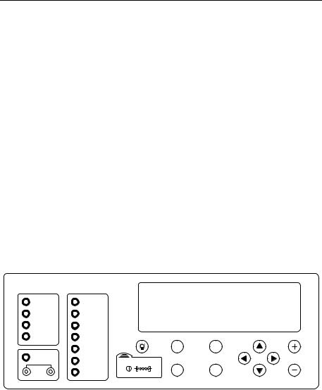
The Millennium’s primary user interface is a panel that includes a backlit LCD front panel display that can be viewed in English or Spanish, two rows of LEDs, an array of pushbutton keys, and a pair of test jacks. Figure 3-1 illustrates the Millennium’s front panel.
Galaxy Millennium Controller
Alarm Status |
Equipment Status |
|
|
Critical |
AC System |
|
|
Major |
Battery |
|
|
Minor |
Controller |
|
|
Normal |
Distribution |
|
|
|
Rectifier |
Escape |
Help |
|
|
|
|
Battery on |
Remote |
|
|
Discharge |
|
|
|
|
Modules |
|
|
V |
Modem |
Menu |
Enter |
|
|
|
|
|
Figure 3-1: Galaxy Millennium Controller Front Panel |
Default Display |
The default display shows basic system status. The controller returns to |
|
|
this display approximately three minutes after the last time a key is |
|
|
pressed. The information on the screen is updated automatically |
|
|
approximately every two seconds. |
|
|
The default screen display is similar to the following: The first line |
|
|
shows the number of alarms (0) and warnings (0) present in the system, |
|
|
the date, and the time. The next two lines show the system voltage and |
|
|
the system load. The last line shows the system mode, which can be one |
|
|
of the following: |
|
|
• |
FLOAT |
|
• |
BOOST |
|
• STC (Slope Thermal Compensation) |
|
|
• |
BATT TEST |
3 - 2 Galaxy Controllers |
Issue 9 Januray 2008 |
Loading...