


GE
AF-650 GP & AF-600 FPTM
PROFINET
Operating Instructions

Contents |
PROFINET Operating Instruction |
|
|
|
|
Contents |
|
|
|
1 Safety |
3 |
|
1.1.2 Safety Note |
3 |
|
1.1.3 Safety Regulations |
3 |
|
1.1.4 Warning against Unintended Start |
4 |
|
2 Introduction |
5 |
|
2.1.1 About this Manual |
5 |
|
2.1.2 Technical Overview |
5 |
|
2.1.3 Assumptions |
5 |
|
2.1.4 Hardware |
5 |
|
2.1.5 Background Knowledge |
5 |
|
2.1.6 Abbreviations |
5 |
|
3 How to Install |
6 |
|
3.1.1 How to Install Option in Frequency Converter |
6 |
|
3.1.2 Network |
7 |
|
3.1.3 PROFINET Cables |
8 |
|
3.1.4 LED Behaviour |
9 |
|
3.1.5 Topology |
11 |
|
3.1.6 Recommended Design Rules |
13 |
|
3.1.7 EMC Precautions |
14 |
|
4 How to Configure |
15 |
|
4.1.1 IP Settings |
15 |
|
4.1.2 Ethernet Link Parameters |
16 |
|
5 How to Configure the System |
17 |
|
5.1 Configure the PROFINET Network |
17 |
|
5.2 Configure the Controller |
17 |
|
5.2.1 GSD File |
17 |
|
5.3 Configure the Frequency Converter |
21 |
|
5.3.1 Drive Parameters |
21 |
|
6 How to Control the Frequency Converter |
22 |
|
6.1 PPO Types |
22 |
|
6.2 Process Data |
23 |
|
6.2.3 Reference Handling |
23 |
|
6.2.4 Process Control Operation |
24 |
|
6.3 Control Profile |
25 |
|
6.4 PROFIdrive Control Profile |
25 |
|
6.5 GE Drive Control Profile |
29 |
1

Contents |
PROFINET Operating Instruction |
|
|
7 PROFINET Acyclic Communication |
33 |
7.1.1 Features of an IO Controller System |
33 |
7.1.2 Features of an IO-Supervisor System |
33 |
7.1.3 Addressing Scheme |
34 |
7.1.4 Acyclic Read/Write Request Sequence |
35 |
7.1.5 Data Structure in the Acyclic Telegrams |
36 |
7.1.6 Header |
36 |
7.1.7 Parameter Block |
36 |
7.1.8 Data Block |
36 |
7.1.9 Header |
37 |
7.1.10 Data Block |
37 |
8 Parameters |
38 |
8.1 Parameter Group O-## Communication and Option |
38 |
8.2 Parameter Group PB-## PROFIdrive |
40 |
8.3 Parameter Group EN-## Ethernet |
42 |
8.4 PROFINET-specific Parameter List |
45 |
8.5 Object and Data Types Supported |
47 |
9 Application Examples |
49 |
9.1 E.g.: Process Data with PPO Type 6 |
49 |
9.2 E.g.: Control Word Network using Standard Telegram 1 / PPO3 |
51 |
9.3 E.g.: Status Word Network using Standard Telegram 1 / PPO3 |
52 |
9.4 E.g.: PLC Programming |
53 |
10 Troubleshooting |
55 |
10.1 Troubleshooting |
55 |
10.1.1 LED Status |
55 |
10.1.2 No Communication with the Drive |
56 |
10.1.3 Warning 34 Appears even though Communication is Established |
57 |
10.1.4 Will Not Respond to Control Signals |
57 |
10.1.5 Alarm and Warning Words |
60 |
11 Warnings and Alarms |
64 |
11.1 Status Messages |
64 |
11.1.1 Warnings/Alarm Messages |
64 |
11.1.2 Alarm List |
64 |
Index |
67 |
2

Safety PROFINET Operating Instruction
1 Safety |
|
1 |
1 |
|
|
|
|
1.1.1 Copyright, Limitation of Liability and |
1.1.2 Safety Note |
|
|
Revision Rights |
|
|
|
This publication contains information proprietary to GE. By accepting and using this manual the user agrees that the information contained herein will be used solely for operating equipment from GE or equipment from other vendors provided that such equipment is intended for communication with GE equipment over an serial communication link. This publication is protected under the Copyright laws of Denmark and most other countries.
GE does not guarantee that a software program produced according to the guidelines provided in this manual will function properly in every physical, hardware or software environment.
Although GE has tested and reviewed the documentation within this manual, GE gives no warranty or representation, either express or implied, with respect to this documentation, including its quality, performance, or fitness for a particular purpose.

 WARNING
HIGH VOLTAGE
The voltage of the frequency converter is dangerous whenever connected to mains. Incorrect installation of the motor, frequency converter or network may cause damage to the equipment, serious personal injury or death. Consequently, the instructions in this manual, as well as national and local rules and safety regulations, must be complied with.
1.1.3 Safety Regulations
1.The drive must be disconnected from mains if repair work is to be carried out. Check that the mains supply has been disconnected and that the necessary time has passed before removing motor and mains plugs.
2.The off-command on the serial bus does not disconnect the equipment from mains and is thus not to be used as a safety switch.
In no event shall GE be liable for direct, indirect, special, incidental, or consequential damages arising out of the use, or the inability to use information contained in this manual, even if advised of the possibility of such damages. In particular, GE is not responsible for any costs including but not limited to those incurred as a result of lost profits or revenue, loss or damage of equipment, loss of computer programs, loss of data, the costs to substitute these, or any claims by third parties.
GE reserves the right to revise this publication at any time and to make changes in its contents without prior notice or any obligation to notify previous users of such revisions or changes.
It has been assumed that all devices will be sitting behind a firewall that does packet filtering and the environment has wellimplemented restrictions on the software that can run inside the firewall. All nodes are assumed to be "trusted" nodes.
3.Correct protective earthing or grounding of the equipment must be established, the user must be protected against supply voltage, and the motor must be protected against overload in accordance with applicable national and local regulations.
4.The earth leakage currents are higher than 3.5mA.
5.Do not remove the plugs for the motor and mains supply while the drive is connected to mains. Check that the mains supply has been disconnected and that the necessary time has passed before removing motor and mains plugs.
3

1 1 |
Safety |
PROFINET Operating Instruction |
|
||
1.1.4 Warning against Unintended Start |
||
1. |
The motor can be brought to a stop by means of |
|
|
|
bus commands while the drive is connected to |
|
|
mains. If personal safety considerations make it |
|
|
necessary to ensure that no unintended start |
|
|
occurs, these stop functions are not sufficient. |
2. |
While parameters are being changed, the motor |
|
|
|
may start. |
3. |
A motor that has been stopped may start if faults |
|
|
|
occur in the electronics of the frequency |
|
|
converter, or if a temporary overload or a fault in |
|
|
the supply mains or the motor connection ceases. |

 WARNING
ELECTRICAL HAZARD
Touching the electrical parts may be fatal - even after the equipment has been disconnected from mains.
4

Introduction PROFINET Operating Instruction
2 Introduction
2.1.1 About this Manual |
2 |
2 |
2.1.4 Hardware |
|
First time users can obtain the most essential information for quick installation and set-up in these chapters:
This manual relates to the PROFINET option OPCPRT.
Introduction
How to Install
How to Configure the System
For more detailed information including the full range of set-up options and diagnosis tools please refer to the chapters:
How to Configure the System
How to Control the AF-600 FP/AF-650 GP
How to Access AF-600 FP/AF-650 GP Parameters
Parameters
Troubleshooting
Terminology:
In this manual several terms for Ethernet are used.
-PROFINET, is the term used to describe the PROFINET protocol.
-Ethernet, is a common term used to describe the physical layer of the network and does not relate to the application protocol.
2.1.2 Technical Overview
Since its introduction in 2001, PROFINET has been updated to handle low and medium performance requirement supported by PROFINET RT (Real Time) up to High end servo performance in PROFINET IRT (Isochronous Real Time). With this, PROFINET is the Ethernet Based Fieldbus offering the most scalable and versatile technology today.
PROFINET provides users with the network tools to deploy standard Ethernet technology for manufacturing applications while enabling Internet and enterprise connectivity.
2.1.3 Assumptions
These operating instructions are under the conditions that the GE PROFINET option is used in conjunction with a GE AF-600 FP or AF-650 GP frequency converter. It is also assumed that the installed controller supports the interfaces described in this document and that all the requirements stipulated in the controller, as well as the frequency converter, are strictly observed along with all limitations herein.
2.1.5 Background Knowledge
The GE PROFINET Option Card is designed to communicate with any system complying with the PROFINET schema version 2.2 standard. For earlier versions of PROFINET, which support schema version 2.1 and earlier, GE recommends an upgrade of the master and other devices connected to the PROFINET network to schema version 2.2. Familiarity with this technology is assumed. Issues regarding hardware or software produced by other manufacturers, including commissioning tools, are beyond the scope of this manual, and are not the responsibility of GE.
For information regarding commissioning tools, or communication to a non-GE node, please consult the appropriate manuals.
2.1.6 Abbreviations
Abbreviation |
Definition |
|
|
API |
Actual Packet Interval |
|
|
CC |
Control Card |
|
|
CTW |
Control Word |
|
|
DCP |
Discovery and Configuration Protocol |
DHCP |
Dynamic Host Configuration Protocol |
EMC |
Electromagnetic Compatibility |
I/O |
Input/Output |
IP |
Internet Protocol |
GSD |
Generic station description |
LED |
Light Emitting Diode |
|
|
LSB |
Least Significant Bit |
|
|
MAV |
Main Actual Value (actual output) |
|
|
MSB |
Most Significant Bit |
|
|
MRV |
Main Reference Value |
|
|
N/A |
Not applicable |
|
|
PC |
Personal Computer |
|
|
PCD |
Process Control Data |
|
|
PLC |
Programmable Logic Controller |
|
|
PNU |
Parameter Number |
|
|
REF |
Reference (= MRV) |
|
|
RT |
Real Time |
RTC |
Real Time Clock |
STP |
Spanning tree Protocol |
STW |
Status Word |
Table 2.1 |
|
5

How to Install |
PROFINET Operating Instruction |
|
|
3 How to Install
3.1.1 How to Install Option in Frequency
Converter
3 3
Items required for installing a network option in the frequency converter:
- The network option
- Network option adaptor frame for the AF-600 FP/ AF-650 GP. This frame is deeper than the standard frame, to allow space for the network option beneath
- Strain relief (only for unit sizes 11 and 12)
|
Illustration 3.2 |
|
Illustration 3.1 |
Instructions: |
|
|
- |
Remove keypad panel from the AF-600 FP/AF-650 |
|
|
GP. |
|
- |
Remove the frame located beneath and discard it. |
|
- |
Push the option into place. The Ethernet |
|
|
connectors must be facing upwards. |
|
- |
Remove both knock-outs on the network option |
|
|
adaptor frame. |
|
- |
Push the network option adaptor frame for the |
|
|
AF-600 FP/AF-650 GP into place. |
|
- |
Replace the keypad and attach cable |
|
NOTE |
|
Do not strip the Ethernet cable and ground it via the strain relief-plate! The grounding of screened Ethernet cable is done through the RJ-45 connector on the option.
NOTE
After installing the OPCPRT option, be aware of the following parameter settings:
O-01 Control Site: [2] Controlword only or [0] Digital and ctrl. word
O-02 Control Word Source: [3] Option A
6

How to Install |
PROFINET Operating Instruction |
|
|
3.1.2 Network
It is of high importance that the media chosen for Ethernet data transmission are suitable. Usually CAT 5e and 6 cables are recommended for industrial applications. Both types are available as Unshielded Twisted Pair and Shielded
Twisted Pair. Generally shielded cables are recommended 3 3 for use in industrial environments and with frequency
converters.
A maximum cable-length of 100m is allowed between switches.
Optical fibres can be used for gapping longer distances and providing galvanic isolation.
For connecting PROFINET devices both hubs and switches can be used. It is, however, recommended always to use suitable industrial graded Ethernet switches. GE recommends always to use PROFINET compliant switches
7

How to Install |
PROFINET Operating Instruction |
|
|
3.1.3 PROFINET Cables
PROFINET cables used are based electrically on category 5 balanced LAN cables according to ISO/IEC 11801 Edition 2.0, Class D.
Type C cables can be used in special applications (e.g. the use of trailing cables and frequently moved machine parts) even though their design and mechanical parameters can deviate from the specifications of type A and type B cables. Still most
3 3 of the electrical parameters (impedance levels etc.) are retained. Highly flexible copper cables generally have the finest stranded conductors and, for example, a highly resistant polyurethane outer sheath.
Various outer sheath materials are permitted in order to meet the various demands with regard to resistance of industrial environments and exterior/underground laying (natural and synthetic oil, grease, coolants/lubricants, chemicals, high and low temperatures, UV radiation).
All balanced cables used shall comply with the following parameters:
Cable Type |
|
Application Type A |
Application Type B |
Application Type C |
|
Design |
|
Data Cable |
Data Cable |
Data Cable |
|
Cable Installation Type |
Stationary, no movement |
Flexible, occasional movement |
Special Applications (e.g. highly flexible, |
||
|
|
after installation |
or vibration |
permanent movement, vibration or torsion) |
|
Cable Marking |
|
PROFINET Type A |
PROFINET Type B |
PROFINET Type C |
|
Core Cross Section |
|
AWG 22/1 |
AWG 22/7 |
AWG 22/.. |
|
|
|
|
|
|
|
Outer Diameter |
|
5,5 - 8,0 mm |
|
|
Application |
|
|
|
|
|
|
Core Diameter |
|
1,5 +/- 0,1 mm |
|
|
Application |
|
|
|
|
|
|
Colour (Outer Sheath) |
Green RAL6018 |
|
|
Application |
|
|
|
|
|
|
|
Core Identification (colours) star |
white, yellow, blue, orange Pair 1: white (RXD+), blue (RXD-) Pair 2: yellow(TXD+), orange(TXT-) |
||||
quad 2 pair |
|
|
|
|
|
|
|
|
|
|
|
Number of Cores |
|
4 |
|
|
|
|
|
|
|
|
|
Cable Design |
|
2 pairs or 1 star quad |
|
|
|
|
|
|
|
|
|
Shielding Design Type |
Aluminum Foil + Cu braiding |
Application |
|||
|
|
|
|
|
|
Which Plug for which Cable Type |
RJ45 (IP 20 or IP 65/67) / M12 |
|
|||
|
|
|
|
|
|
|
|
|
|
|
|
Table 3.1 |
|
|
|
|
|
Transmission Performance Requirements: |
|
|
|
||
|
|
|
|
|
|
Relevant Standard |
ISO/IEC 11801 Edition 2.0, IEC 61156 |
|
|
|
|
|
(minimum Category 5) |
|
|
|
|
|
|
|
|
|
|
Delay Skew |
<=20ns/100m |
|
|
|
|
|
|
|
|
|
|
Transfer Impedance |
<=50mOhm/m at 10MHz |
|
|
|
|
|
|
|
|
|
|
Table 3.2
8

How to Install |
PROFINET Operating Instruction |
|
|
3.1.4 LED Behaviour
The option has 3 bi-coloured LEDs that allow a fast and detailed diagnosis. The three LEDs are each linked to its unique part of the PROFINET option:
|
|
3 |
3 |
LED Label |
Description |
||
MS |
Module Status, reflects the activity on the |
|
|
|
PROFINET stack |
|
|
NS1 |
Network Status 1, reflects the activity on port 1 |
|
|
NS2 |
Network Status 2, reflects the activity on port 2 |
|
|
Table 3.3
Illustration 3.3 Overview of the Option
9
How to Install |
PROFINET Operating Instruction |
|
|
Module Status
|
|
Status |
Tri-colour LED |
|
|
|
No IP Address assigned |
Off |
|
|
|
No Communication to PROFINET module. Module is waiting for configu- |
Green: |
|
3 |
3 |
ration telegram from Controller. |
|
|
IO AR established |
Green: |
|||
|
|
Supervisor AR established, No IO AR. |
Green: |
|
|
|
|
|
|
|
|
|
|
|
|||||
|
|
|
|
|
|
|
|
|
|
|
|||||||
|
|
|
|
|
|
|
|
|
|
|
|
|
|
|
|
|
|
|
|
|
|
|
|
|
|
|
|
|
|
|
|
|
|
|
|
Internal Error |
|
Red: |
|
|
|
|
|
|
|
|
|
|
|
|
|||
|
|
|
|
|
|
|
|
|
|
|
|
|
|||||
|
|
|
|
|
|
|
|
|
|
|
|
|
|
|
|
|
|
|
|
|
|
|
|
|
|
|
|
|
|
|
|
|
|
|
|
|
|
|
|
|
|
|
|
|
|
|
|
|
|
|
|
|
|
Wink |
|
Yellow: |
|
|
|
|
|
|
|
|
|
|
|
|
|||
|
|
|
|
|
|
|
|
|
|
|
|
|
|||||
|
|
|
|
|
|
|
|
|
|
|
|
|
|
|
|
|
|
|
|
|
|
|
|
|
|
|
|
|
|
|
|
|
|
|
|
Table 3.4 MS: Module Status |
|
|
|
|
|
|
|
|
|
|
|
|
|
|
|
|
|
Network Status |
|
|
|
|
|
|
|
|
|
|
|
|
|
|
|
|
|
Phases |
Status |
|
|
|
|
|
|
|
|
Tri-colour LED |
|
||||||
|
|
|
|
|
|
||||||||||||
Power Off |
No Power or No Link on the corresponding port |
|
Off |
|
|
||||||||||||
|
|
|
|
|
|
|
|
|
|
|
|
|
|
|
|
|
|
|
IP Address Conflict |
|
Red: |
|
|
|
|
|
|
|
|
|
|
|
|
|
|
|
|
|
|
|
|
|
|
|
|
|
|
|
|||||
Power On |
|
|
|
|
|
|
|
|
|
|
|
|
|
|
|
|
|
Waiting for configuration |
|
Green: |
|
|
|
|
|
|
|
|
|
|
|
|
|
|
|
|
|
|
|
|
|
|
|
|
|
|
|
|
|
|
|||
|
|
|
|
|
|
|
|
|
|
|
|
|
|
|
|
|
|
|
|
|
|
|
|
|
|
|
|
|
|
|
|
|
|
|
|
|
In Data Exchange Mode |
|
Green: |
|
|
|
|
|
|
|
|
|
|
|
|
|
|
|
|
|
|
|
|
|
|
|
|
|
|
|
|||||
Running |
|
|
|
|
|
|
|
|
|
|
|
|
|
|
|
|
|
Wrong Configuration |
|
Red: |
|
|
|
|
|
|
|
|
|
|
|
|
|
|
|
|
|
|
|
|
|
|
|
|
|
|
|
|
|
|
|
||
|
|
|
|
|
|
|
|
|
|
|
|
|
|
|
|
|
|
|
|
|
|
|
|
|
|
|
|
|
|
|
|
|
|
|
|
Data exchange |
No increment in "In Octets" counter of |
|
Yellow: |
|
|
|
|
|
|
|
|
|
|
|
|
|
|
|
|
|
|
|
|
|
|
|
|
|
|
|
|
|
|||
corresponding port in last 60 secs. |
|
|
|
|
|
|
|
|
|
|
|
|
|
|
|||
|
|
|
|
|
|
|
|
|
|
|
|
|
|
|
|
|
|
|
|
|
|
|
|
|
|
|
|
|
|
|
|
|
|
|
|
|
|
|
|
|
|
|
|
|
|
|
|
|
|
|
|
|
|
Table 3.5 Indication on Network Status LED |
|
|
|
|
|
|
|
|
|
|
|
|
|
|
|
|
|
During normal operation the MS and at least one NS LED will show a constant green light.
Wink command
The option will responds to a Wink command from the network by yellow flashing of all three LEDs simultaneously.
10

How to Install |
PROFINET Operating Instruction |
|
|
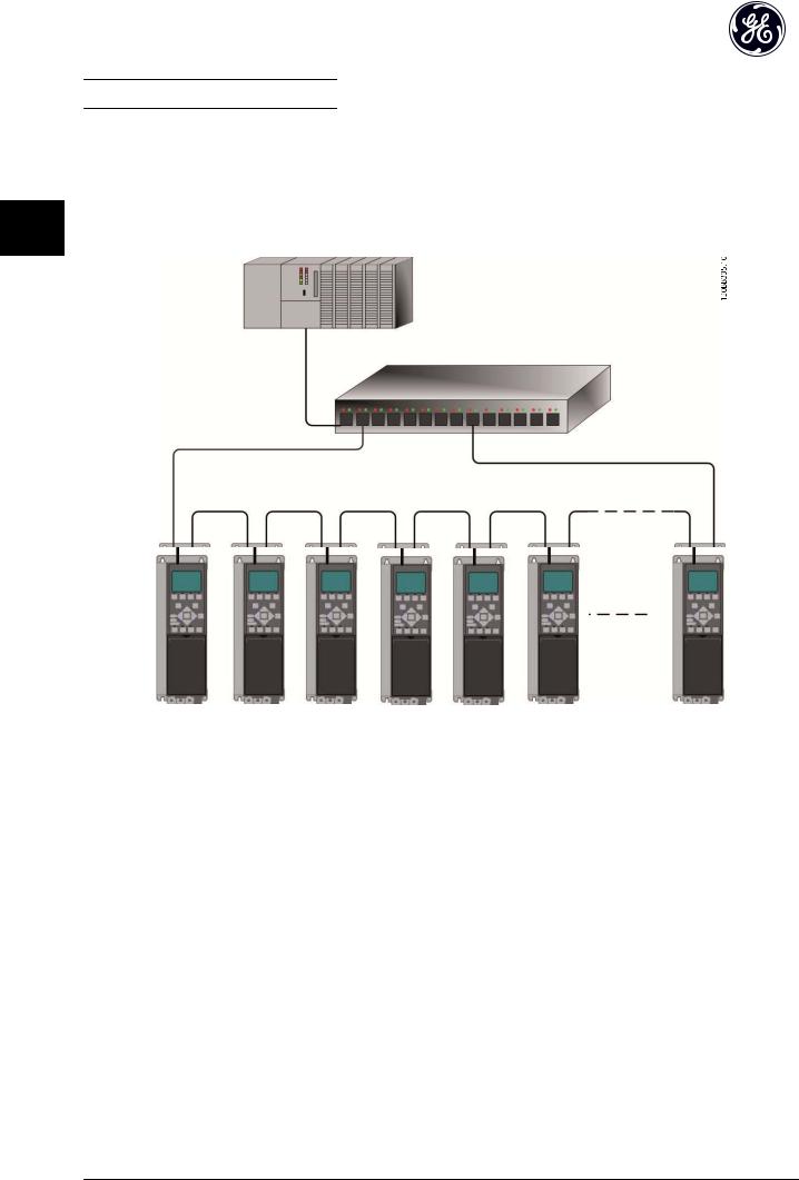
3.1.5 Topology
The PROFINET module features a built-in Ethernet-switch, thus having two Ethernet RJ-45 connectors. This enables the possibility for connecting several PROFINET options in a line topology as an alternative to the typical star-topology.
The two ports are equal, in the sense that they are transparent for the option. If only one connector is used, both ports can |
3 |
3 |
be used. |
Illustration 3.4 Star Topology
Illustration 3.5 Line Topology
11
How to Install PROFINET Operating Instruction
NOTE
|
|
In a line topology all drives must be powered, either by mains or by their 24V DC option cards, for the built-in switch to |
||||||||||||||||||||||||||||||||||||
|
|
work. |
||||||||||||||||||||||||||||||||||||
|
|
Please observe that mounting drive of different power-sizes in a line topology may result in unwanted power-off behavior, |
||||||||||||||||||||||||||||||||||||
|
|
while using controlword timeout (O-02 Control Word Source to O-06 Reset Control Word Timeout. It is recommended to |
||||||||||||||||||||||||||||||||||||
3 |
3 |
mount the drives with the longest discharge time first in the line topology. |
||||||||||||||||||||||||||||||||||||
|
|
|
|
|
|
|
|
|
|
|
|
|
|
|
|
|
|
|
|
|
|
|
|
|
|
|
|
|
|
|
|
|
|
|
|
|
||
|
|
|
|
|
|
|
|
|
|
|
|
|
|
|
|
|
|
|
|
|
|
|
|
|
|
|
|
|
|
|
|
|
|
|
|
|
|
|
|
|
|
|
|
|
|
|
|
|
|
|
|
|
|
|
|
|
|
|
|
|
|
|
|
|
|
|
|
|
|
|
|
|
|
|
|
|
|
|
|
|
|
|
|
|
|
|
|
|
|
|
|
|
|
|
|
|
|
|
|
|
|
|
|
|
|
|
|
|
|
|
|
|
|
|
|
|
|
|
|
|
|
|
|
|
|
|
|
|
|
|
|
|
|
|
|
|
|
|
|
|
|
|
|
|
|
|
|
|
|
|
|
|
|
|
|
|
|
|
|
|
|
|
|
|
|
|
|
|
|
|
|
|
|
|
|
|
|
|
|
|
|
|
|
|
|
|
|
|
|
|
|
|
|
|
Illustration 3.6 Ring/Redundant Line Topology
CAUTION
For this type of topology it is crucial that the network switch supports detection of loss of line topology. In some cases the detection. The switch inside the PROFINET option does not support this, but it must be supported in the switch that connects the ring to the controller/network Please consult the manual of the switch for more information.
12

How to Install |
PROFINET Operating Instruction |
|
|
3.1.6 Recommended Design Rules
While designing Ethernet networks special attention and caution must be taken regarding active network components. While designing a network for line topology it is important to notice that a small delay is added with each switch in the line.
It is not recommended to connect more than 32 drive in a line. Exceeding the recommended design rules, may result in |
3 |
3 |
|||||||||||||||||||||||||
unstable or faulted communication. |
|
|
|||||||||||||||||||||||||
|
|
|
|
|
|
|
|
|
|
|
|
|
|
|
|
|
|
|
|
|
|
|
|
|
|
|
|
|
|
|
|
|
|
|
|
|
|
|
|
|
|
|
|
|
|
|
|
|
|
|
|
|
|
|
|
|
|
|
|
|
|
|
|
|
|
|
|
|
|
|
|
|
|
|
|
|
|
|
|
|
|
|
|
|
|
|
|
|
|
|
|
|
|
|
|
|
|
|
|
|
|
|
|
|
|
|
|
|
|
|
|
|
|
|
|
|
|
|
|
|
|
|
|
|
|
|
|
|
|
|
|
|
|
|
|
|
|
|
|
|
|
|
|
|
|
|
|
|
|
|
|
|
|
|
|
|
|
|
|
|
|
|
|
|
|
|
|
|
|
|
|
|
|
|
|
|
|
|
|
|
|
|
|
|
|
|
|
|
|
|
|
|
|
|
|
|
|
|
|
|
|
|
|
|
|
|
|
|
|
|
|
|
|
|
|
|
|
|
|
|
|
|
|
|
|
|
|
|
|
|
|
|
|
|
|
|
|
|
|
|
|
|
|
|
|
|
|
|
|
|
|
|
|
|
|
|
|
|
|
|
|
|
|
|
|
|
|
|
|
|
|
|
|
|
|
|
|
|
|
|
|
|
|
|
|
|
|
|
|
|
|
|
|
|
|
|
|
|
|
|
|
|
|
|
|
|
|
|
|
|
|
|
|
|
|
|
|
|
|
|
|
|
|
|
|
|
|
|
|
|
|
|
|
|
|
Illustration 3.7
13

How to Install |
PROFINET Operating Instruction |
|
|
3.1.7 EMC Precautions
The following EMC precautions are recommended in order to achieve interference-free operation of the Ethernet network. Additional EMC information is available in the AF-600 FP/AF-650 GP series Design Guide.
3 3 NOTE
Relevant national and local regulations, for example regarding protective earth connection, must be observed.
The Ethernet communication cable must be kept away from motor and brake resistor cables to avoid coupling of high frequency noise from one cable to the other. Normally a distance of 200mm (8 inches) is sufficient, but maintaining the greatest possible distance between the cables is recommended, especially where cables run in parallel over long distances. When crossing is unavoidable, the Ethernet cable must cross motor and brake resistor cables at an angle of 90°.
Illustration 3.8
14

How to Configure |
PROFINET Operating Instruction |
|
|
4 How to Configure
4.1.1 IP Settings
All IP-related parameters are located in parameter group EN-##: The parameters are all set to PROFINET standard values, so that only a minimum change is necessary.
EN-00 IP Address Assignment
EN-01 IP Address
EN-02 Subnet Mask
EN-03 Default Gateway
EN-04 DHCP Server
EN-05 Lease Expires
EN-06 Name Servers
EN-07 Domain Name
EN-08 Host Name
EN-09 Physical Address
The PROFINET option offers several ways of IP address assignment.
Setting up drive with manual assigned IP address:
Parameter |
Value |
|
|
|
|
EN-00 |
IP Address |
[0] MANUAL |
Assignment |
|
|
|
|
|
EN-01 |
IP Address |
192.168.0.003* |
|
|
|
EN-02 |
Subnet Mask |
255.255.255.0* |
|
|
|
EN-03 |
Default |
optional |
Gateway |
|
|
|
|
|
Table 4.1
*= Class C IP address example. Any valid IP address can be entered.
EN-09 Physical Address reads out the MAC address of |
|
|
|
option, which is also printed on the label of the option. If |
|
|
|
using fixed leases together with DHCP or BOOTP, the |
4 |
4 |
|
physical MAC address is linked with a fixed IP address. |
|||
|
|
NOTE
If no DHCP or BOOTP reply has been received after 4 attempts (e.g. if the DHCP/BOOTP server has been powered off), the option will fallback to the last functioning IP address.
EN-03 Default Gateway is optional and only used in routed networks.
EN-06 Name Servers
EN-07 Domain Name EN-08 Host Name
are used with Domain Name Server systems and are all optional. If DHCP or BOOTP is selected as IP address assignment, these parameters are read only.
NOTE
It is only possible to assign valid class A, B and C IP address to the option. The valid ranges are shown in
Table 4.3:
Class A 1.0.0.1 - 126.255.255.254
Class B 128.1.0.1 - 191.255.255.254
Class C 192.0.1.1 - 223.255.254.254
Table 4.3
Setting up drive with automatic (BOOTP/DHCP) assigned IP address:
Parameter |
Value |
|
EN-00 |
IP Address |
[0] MANUAL/[1] DHCP/[2] BOOTP/[10] DCP |
Assignment |
|
|
EN-01 |
IP Address |
Read only |
|
|
|
EN-02 |
Subnet Mask |
Read only |
|
|
|
EN-03 |
Default |
Read only |
Gateway |
|
|
|
|
|
Table 4.2 |
|
|
By IP address assigned by DHCP/BOOTP/DCP server, the assigned IP Address and Subnet Mask can be read out in
EN-01 IP Address and EN-02 Subnet Mask. In EN-04 DHCP Server the IP address of the found DHCP or BOOTP server is displayed. For DHCP only: The remaining lease-time can be read-out in EN-05 Lease Expires. If lease time is set to 0 (zero) the timer will never expire.
15

How to Configure |
PROFINET Operating Instruction |
|
|
4.1.2 Ethernet Link Parameters
Parameter group EN-1# holds information Ethernet Link information:
EN-10 Link Status |
|
EN-11 |
Link Duration |
EN-12 Auto Negotiation |
|
4 4 EN-13 |
Link Speed |
EN-14 |
Link Duplex |
Please note the Ethernet Link Parameters are unique per port.
EN-10 Link Status and EN-11 Link Duration displays information on the link status, per port.
EN-10 Link Status will display Link or No Link according to the status of the present port.
EN-11 Link Duration will display the duration of the link on the present port. If the link is broken the counter will be reset.
EN-12 Auto Negotiation - is a feature that enables two connected Ethernet devices to choose common transmission parameters, such as speed and duplex mode. In this process, the connected devices first share their capabilities as for these parameters and then choose the fastest transmission mode they both support.
Incapability between the connected devices, may lead to decreased communication performance.
To prevent this, Auto Negotiation can be disabled.
If EN-12 Auto Negotiation is set to OFF, link speed and duplex mode can be configured manually in EN-13 Link Speed and EN-12 Auto Negotiation.
EN-13 Link Speed - displays/sets the link speed per port. “None” is displayed if no link is present.
EN-14 Link Duplex - displays/sets the duplex mode per port. Half-duplex provides communication in both directions, but only in one direction at a time (not simultaneously). Full-duplex allows communication in both directions, and unlike half-duplex, allows for this to happen simultaneously.
16
How to Configure the System |
PROFINET Operating Instruction |
|
|
5 How to Configure the System
5.1 Configure the PROFINET Network
All PROFINET devices that are connected to the same network must have a unique device name.
The PROFINET device name of the frequency converter can be set via:
EN-08 Host Name
5.2 Configure the Controller
5.2.1 GSD File
In order to configure a PROFINET Controller, the configuration tool needs a GSD file for each type of slave on the network. The GSD file is a PROFINET standard text file containing the necessary communication setup data for a slave. Download the GSD file for the AF-6 Series drives at www.geelectrical.com/drives. The name of the GSD file may vary compared to this manual. Please download the latest version from the above website.
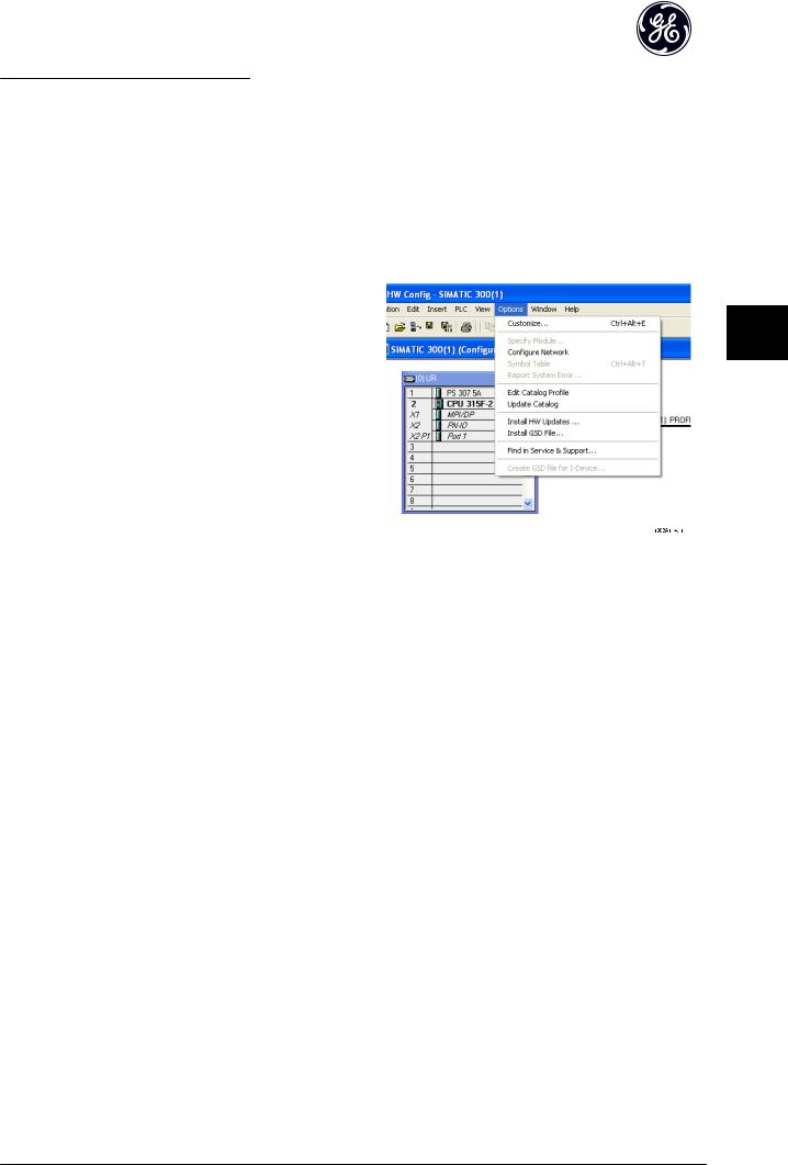
The first step in configuration of the PROFINET Controller is to import the GSD file in the configuration tool. The steps
outlined below show how to add a new GSD file to the Simatic Manager software tool. For each drive series, a GSD file is typically imported once only, following the initial installation of the software tool.
5 5
Illustration 5.1
17

How to Configure the System |
PROFINET Operating Instruction |
|
|
5 5
Illustration 5.2
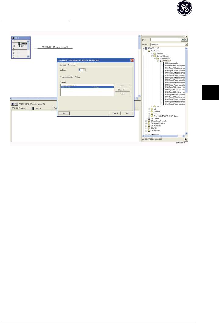
The GSD file is now imported and will be accessible via the following path in the Hardware catalogue:
Illustration 5.3
Open a Project, set up the Hardware and add a PROFINET Master system. Select GE FC PN then drag and drop it onto the PROFINET IO system.
A window for the Device name of the now appears. Type the name into the field. Note that the name must match the name in EN-08 Host Name. If the checkmark Assign IP address via the IO controller is set, the controller will download the IP address to the IO device that has the corresponding device name. The IP address is stored in the non volatile memory of the .
18
How to Configure the System |
PROFINET Operating Instruction |
|
|
5 5
Illustration 5.4
The next step is to set up the peripheral input and output data. Data set up in the peripheral area is transmitted cyclically via telegrams/PPO types. In the example below, a PPO type 6 is dragged and dropped to slot 1.
See the PPO types section in How to Control the Frequency Converter for more information.
19

How to Configure the System |
PROFINET Operating Instruction |
|
|
5 5
Illustration 5.5
The configuration tool automatically assigns addresses in the peripheral address area. In this example the input and output area have the following configuration:
PPO type 6:
PCD word number |
0 |
1 |
2 |
3 |
Input address |
256-257 |
258-259 |
260-261 |
262-263 |
Set-up |
STW |
MAV |
PB-16 PCD Read Configuration.2 |
PB-16 PCD Read Configuration.3 |
|
|
|
|
|
Table 5.1 PCD Read (Drive to PLC)
PCD word number |
0 |
1 |
2 |
3 |
|
|
|
|
|
Output address |
256-257 |
258-259 |
260-261 |
262-263 |
|
|
|
|
|
Set-up |
CTW |
MRV |
PB-15 PCD Write Configuration.2 |
PB-15 PCD Write Configuration.3 |
|
|
|
|
|
Table 5.2 PCD Write (PLC to Drive)
The PCDs have to be assigned via PB-16 PCD Read Configuration for inputs and PB-15 PCD Write Configuration for outputs.
Download the configuration file to the PLC. The PROFINET system should be able to go online and it will start to exchange data when the PLC is set to Run mode.
20
 Loading...