


g
GEK-86132G Instructions
PowerVac® Vacuum Circuit Breaker with ML-18 or ML-18H Mechanism
_______________________________________________________________________________
1

PowerVac ® Vacuum Circuit Breaker
With ML-18 or ML-18H Mechanism
Table of Contents |
|
|
Description |
Page |
|
SECTION 1 Introduction.............................................. |
4 |
|
1.1 |
Safety.............................................................................. |
4 |
1.2 |
Maintenance ................................................................... |
4 |
SECTION 2 Description................................................ |
5 |
|
2.1 |
General............................................................................ |
5 |
2.2 |
Summary Description...................................................... |
5 |
SECTION 3 Receiving, Handling and |
|
|
|
Storage...................................................... |
5 |
3.1 |
Receiving ........................................................................ |
5 |
|
A. Equipment Packages................................................. |
5 |
|
B. Inspecting for Damage .............................................. |
5 |
|
C. Filing a Claim............................................................. |
5 |
3.2 |
Handling .......................................................................... |
5 |
3.3 |
Storage............................................................................ |
5 |
SECTION 4 Features....................................................... |
6 |
|
4.1 |
Safety Precautions........................................................... |
6 |
4.2 |
Interlocks......................................................................... |
6 |
4.2.1 |
Rating Interference Plate................................................. |
6 |
4.2.2 |
Closing Spring Interlock ................................................... |
7 |
4.2.3 |
Negative Interlock............................................................ |
7 |
4.2.4 |
Positive Interlock Bar....................................................... |
7 |
4.2.5 |
Closing Spring Gag Interlock............................................ |
7 |
Description |
Page |
|
SECTION 9 Electrical Checks.................................. |
14 |
|
9.1 |
Electrical Operation......................................................... |
14 |
9.2 |
High Potential Test.......................................................... |
14 |
9.2.1 |
Primary Circuit................................................................. |
14 |
9.2.2 |
Secondary Circuit ............................................................ |
14 |
9.3 |
Primary Circuit Resistance .............................................. |
14 |
9.4 |
Vacuum Interrupter Integrity Test.................................... |
14 |
9.5 |
Insulation Test................................................................. |
15 |
SECTION 10 Checking and Installing |
|
|
|
Breakers................................................. |
16 |
SECTION 11 Maintenance......................................... |
17 |
|
11.1 |
General ........................................................................... |
17 |
11.1.1 |
PowerVac Interrupter ...................................................... |
17 |
11.1.2 |
Trouble Reporting ........................................................... |
17 |
11.2 |
Service Conditions .......................................................... |
17 |
11.3 |
Fault Interruptions ........................................................... |
17 |
11.4 |
Contact Erosion............................................................... |
17 |
11.5 |
Transfer Finger Wear...................................................... |
17 |
11.6 |
Mechanism ..................................................................... |
17 |
11.7 |
Primary Insulation Parts................................................... |
17 |
11.8 |
Lubrication ...................................................................... |
18 |
11.9 |
Recommended Maintenance.......................................... |
18 |
SECTION 12 Timing........................................................ |
19 |
|
SECTION 5 Operation |
|
SECTION 13 Opening and Closing Speed ... |
20 |
|||
8 |
|
|
|
|||
5.1 |
General............................................................................ |
8 |
SECTION 14 Repair and Replacement............ |
21 |
||
5.2 |
Close Spring Charging ..................................................... |
8 |
14.1 |
General |
21 |
|
5.3 |
Closing Operation |
8 |
||||
14.2 |
Replacement of Interrupter Assemblies |
21 |
||||
5.4 |
Opening Operation |
9 |
||||
14.3 |
Primary Disconnect Fingers |
21 |
||||
5.5 |
Trip-free Operation |
9 |
||||
14.4 |
Mechanism |
21 |
||||
|
|
|
||||
|
|
|
14.5 |
Control Switches............................................................. |
21 |
|
SECTION 6 Control Circuit........................................ |
9 |
14.6 |
Trip Coil Replacement..................................................... |
21 |
||
|
|
|
14.7 |
Closing Coil Replacement............................................... |
22 |
|
SECTION 7 Mechanical Checking and |
|
14.8 |
Auxiliary Switch Replacement......................................... |
22 |
||
|
14.9 |
Motor Replacement........................................................ |
22 |
|||
|
Slow Closing |
9 |
14.10 |
“Y” Relay Replacement................................................... |
22 |
|
|
|
|
|
|||
7.1 |
Visual Inspection.............................................................. |
9 |
SECTION 15 Renewal Parts |
23 |
||
7.2 |
Closing Spring Charging |
10 |
||||
15.1 |
Ordering Instructions |
23 |
||||
7.3 |
Closing Spring Gag |
10 |
||||
|
|
|
||||
7.4 |
Slow Closing.................................................................... |
10 |
SECTION 16 Mechanical Adjustment |
23 |
||
7.5 |
Gag Plate Removal.......................................................... |
10 |
||||
|
|
|
16.1 |
General ........................................................................... |
23 |
|
SECTION 8 Dimensional Checks |
11 |
16.2 |
Wipe Adjustment............................................................ |
23 |
||
16.3 |
Contact Gap Adjustment |
23 |
||||
8.1 |
Primary Contact Erosion |
11 |
||||
16.4 |
Trip Coil Plunger |
24 |
||||
8.2 |
ML-18 Wipe Spring Compression |
11 |
||||
16.5 |
Close Coil Plunger |
24 |
||||
8.3 |
ML-18H Wipe Spring Compression |
11 |
||||
16.6 |
Close Latch Stop Bolt |
24 |
||||
8.4 |
Contact Gap |
11 |
||||
16.7 |
Closing Spring Discharge Interlock |
24 |
||||
8.5 |
Coil Plunger Gap |
11 |
||||
16.8 |
Negative Interlock |
24 |
||||
8.6 |
Control Switch Adjustment |
12 |
||||
|
|
|
||||
8.6.1 |
LCS and SM/LS Switch Adjustment................................. |
12 |
INDEX |
|
37 |
|
8.6.2 |
CL/MS Switch Adjustment |
12 |
........................................................................................ |
|||
Trouble Reporting Form |
39 |
|||||
8.6.3 |
IL/MS Switch Adjustment................................................ |
13 |
||||
2

List of Illustrations
Figure |
Page |
|
1 |
Front view of PowerVac® breaker with front cover ................... |
6 |
2 |
Rating interference plate........................................................... |
6 |
3 |
Front view of PowerVac breaker without front cover................ |
8 |
4 |
Manual charging........................................................................ |
9 |
5 |
Gag plate installation................................................................. |
10 |
6 |
Operating rod assembly ............................................................ |
10 |
7 |
Contact gap............................................................................... |
11 |
8 |
Breaker turned on right side...................................................... |
11 |
9 |
Close coil plunger gap............................................................... |
12 |
10 |
Trip coil plunger gap.................................................................. |
12 |
11 |
Control switches ....................................................................... |
13 |
12 |
Sample operating speed graphs................................................ |
19 |
13 |
Contact gap adjustment ............................................................ |
20 |
14 |
Auxiliary switch position............................................................ |
22 |
15 |
Spring discharge interlock ......................................................... |
24 |
16 |
Toggle linkage positions of the ML-18 mechanism................... |
25 |
17 |
Schematic of ML-18 mechanism............................................... |
27 |
18 |
Typical wiring diagram for ML-18 mechanism........................... |
29 |
19 |
PowerVac® breaker left-front view............................................ |
30 |
20 |
PowerVac® breaker right-rear view ........................................... |
30 |
21 |
Trip coil and linkage................................................................... |
31 |
22 |
Close coil linkage....................................................................... |
32 |
23 |
Bottom view of the ML-18 mechanism..................................... |
33 |
24 |
Flex cable connections.............................................................. |
34 |
25 |
Negative interlock ..................................................................... |
34 |
26 |
Close latch stop......................................................................... |
35 |
27 |
Wipe spring............................................................................... |
35 |
Table |
Page |
|
1 |
Control Device and Voltage |
..................................................... 18 |
2 |
Measurements ....................................................................... |
36 |
3 |
Adjustments............................................................................ |
36 |
THESE INSTRUCTIONS ARE INTENDED FOR USE BY QUALIFIED PERSONNEL FOR INSTRUCTION AND MAINTENANCE PURPOSES. REPRODUCTION IN WHOLE OR IN PART IS NOT PERMITTED WITHOUT THE EXPRESS PERMISSION OF GENERAL ELECTRIC.
3
PowerVac® Vacuum Circuit Breaker
With ML-18 or ML-18H Mechanism
SECTION 1—Introduction
This manual provides the information needed by the user to properly install, operate and maintain the ML-18 or ML-18H PowerVac® Breaker.
The PowerVac® vacuum breaker is a horizontal drawout, removable and interchangeable interrupting element for use in metalclad switchgear to provide protection and control of electrical apparatus and power systems. To the extent required applicable ANSI, IEEE and NEMA Standards are met. No such assurances are given with respect to local codes and ordinances, as they vary greatly.
1.1—Safety
Each user must maintain a safety program for the protection of personnel, as well as other equipment, from the potential hazards associated with electrical equipment.
The following requirements are intended to augment the user's safety program, but NOT supplant the user's responsibility for devising a complete safety program. The following basic industry practiced safety requirements are applicable to all major electrical equipment such as switchgear or switchboards. GE neither condones nor assumes any responsibility for practices which deviate from the following:
1.ALL CONDUCTORS MUST BE ASSUMED TO BE ENERGIZED UNLESS THEIR POTENTIAL HAS BEEN MEASURED AS GROUND AND ADEQUATE CAPACITY GROUNDING ASSEMBLIES HAVE BEEN APPLIED TO PREVENT ENERGIZING. Many accidents have been caused by unplanned energization from non-recognized back feeds, equipment malfunctions, and from a wide variety of sources.
2.VACUUM CIRCUIT BREAKERS ARE NOT TO BE
CONSIDERED AS AN ISOLATING MEANS FOR PROVIDING SAFETY TO PERSONEL UNLESS WITHDRAWN TO FULLY “DISCONNECTED/TEST” POSITION. In the “CONNECTED” position with the interrupter contacts separated (breaker open), small leakage current with high voltages can flow across the gap. In addition, leakage current can flow across the bottle or interrupter assembly if dirty or high humidity is providing a path for tracking.
3.It is strongly recommended that all equipment be completely de-energized, verified to be “dead”, then grounded with adequate capacity grounding assemblies prior to any maintenance. The grounding cable assemblies must be able to withstand energizing fault levels so that protective equipment may clear the circuit safely. Additional discussion on this concept is covered in Chapter 20 of ANSI/NFPA 70B, Electrical Equipment
Maintenance.
4.Although interlocks to reduce some of the risks are provided, the individual's actions while performing service or maintenance are essential to prevent accidents. Each person's knowledge; mental awareness; and planned and executed actions often determine if an accident will occur. The most important method of avoiding accidents
4
is for all associated personnel to carefully apply a thorough under-standing of the specific equipment from the viewpoints of its purpose, its construction, its operation and the situations which could be hazardous.
All personnel associated with installation, operation and maintenance of electrical equipment, such as power circuit breakers and other power handling equipment, must be thoroughly instructed, with periodic retraining, regarding power equipment in general as well as the particular model of equipment with which they are working.
Instruction books, actual devices and appropriate safety and maintenance practices such as OSHA publications, National Electric Safety Code (ANSI C2), National Electric Code, and National Fire Protection Association (NFPA) 70B Electrical Equipment Maintenance must be closely studied and followed. During actual work, supervision should audit practices to assure conformance.
1.2—Maintenance
Excellent maintenance is essential for reliability and safety of any electrical equipment. Maintenance programs must be tuned to the specific application, well planned and carried out consistent with both industry experience and manufacturer's recommendations. Local environment must always be considered in such programs, including such variables as ambient temperatures, extreme moisture, number of operations, corrosive atmosphere or major insect problems and any other unusual or abusive condition of the application. One of the critical service activities, sometimes neglected, involves the calibration of various control devices. These monitored conditions in the primary and secondary circuits, sometimes initiating emergency corrective action such as opening or closing circuit breakers. In view of the vital role of these devices, it is important that a periodic test program be followed. As was outlined above, it is recognized that the interval between periodic checks will vary depending upon environment, the type of device and the user's experience.
It is the GE recommendation that, until the user has accumulated enough experience to select a test interval better suited to the individual requirements, all significant calibrations be checked at an interval of one to two years.
To accomplish this, some devices can be adequately tested using test sets. Specific calibration instructions on particular devices typically are provided by supplied instruction books.
Instruction books supplied by manufacturers address components that would normally require service or maintenance during the useful life of the equipment. However, they can not include every possible part that could under adverse environments. Maintenance personnel must be alert to deterioration of any part of the supplied switchgear, taking actions, as necessary to restore it to serviceable status.
Industry publications of recommended maintenance practices such as ANSI/NFPA 70B, Electrical Equipment Maintenance,

should be carefully studied and applied in each user's formation of planned maintenance.
Some users may require additional assistance from GE in the planning and performance of maintenance. Local GE Sales can be contracted to either undertake maintenance or to provide technical assistance such as the latest publications.
SECTION 2—Description
2.1—General
This section contains a description of the PowerVac® vacuum circuit breaker. It also describes the functions of the electrical and mechanical systems.
2.2—Summary Description
The PowerVac® vacuum circuit breaker uses sealed vacuum power interrupters to establish and interrupt a primary circuit. Primary connections to the associated metalclad switchgear are made by horizontal bars and disconnect fingers, electrically and mechanically connected to the vacuum interrupters. Molded interrupter supports, one per phase on a three-phase circuit breaker, provide mountings for the primary bars, interrupters, current transfer fingers, and heat dissipation fins (where used). The operating mechanism provides direct motion at each phase location in order to move the movable contact of the vacuum interrupters from an open position to a spring-loaded closed position and then back to the open position on command.
The performance and safety of all equipment may be compromised by the modification of supplied parts or their replacement by non-identical substitutes. All such design changes must be qualified to the original manufacturers specifications.
The user should methodically keep written maintenance records as an aid in future service planning and equipment reliability improvement. Unusual experiences should be promptly communicated to G.E.
The ML-18 and ML-18H mechanisms are of the stored-energy type and use a gear motor to charge a closing spring. During a closing operation, the energy stored in the closing spring is used to close the vacuum interrupter contacts, compress the wipe springs which load the contacts, charge the opening spring, and overcome bearing and other friction forces, The energy then stored in the wipe springs and opening spring will open the contacts during an opening operation.
Closing and opening operations are controlled electrically by the metalclad switchgear or remote relaying. Mechanical control is provided by manual close and trip buttons on the circuit breaker. The closing spring may be manually charged, and a method for slow-closing the primary contacts is available. The mechanism will operate at the ac or dc voltage indicated on the circuit breaker nameplate.
Mechanical and electrical interlocks are provided and are described in Section 4.2, Interlock.
SECTION 3—Receiving, Handling and Storage
3.1—Receiving
A. Equipment Packages
Every package leaving the factory is plainly marked with the case number, requisition number, and customer’s order number. If the equipment has been split for shipment, the section numbers of the equipment enclosed in each shipping package are identified.
NOTE: To avoid loss of any parts when unpacking, the  contents of each container should be carefully checked
  against the packing list before discarding the packing material.
Contents of each shipping package are listed on the Master
Packing List. In addition, this list includes the number of the shipping crate in which miscellaneous parts needed to install and operate equipment (such as hardware, contact lubricant, touch-up paint, breaker closing devices, etc.) are located.
Normally, such devices are packed in a cardboard carton and the carton secured in an empty switchgear compartment. If such items are packed in a switchgear section instead of a separate crate, the list will indicate appropriate section number in which they are stored. Large items (such as breaker lift trucks used with indoor and outdoor equipment) will always be shipped in separate crates or cartons.
B. Inspecting for Damage
All equipment leaving the factory is carefully inspected and packed by personnel experienced in the proper handling and
packing of electrical equipment. Upon receipt of any equipment, immediately perform a visual inspection to ascertain if any damage has been sustained in shipping or if there are any loose parts.
C. Filing a Claim
If any damage is evident, or indication of rough handling is visible, file a claim for damage at once with the transportation company and notify the nearest General Electric Company Sales Office immediately. Information on damaged parts, part number, case number, requisition number, etc., should accompany the claim.
3.2—Handling
When lifting the breaker, use of the specially designed lift truck is recommended. It is necessary to use the lift truck when placing a breaker into or removing it from the metalclad switchgear unless the breaker is equipped with a roll-in undercarriage (bottom only) . If it is necessary to lift the breaker with a hoist use four 1/2 inch diameter hooks rated at least 500 pounds each. Lifting locations are provided in the side frame members. Use a spreader wider than the breaker to prevent slings from contacting the interrupter supports.
3.3—Storage
It is recommended that the breaker be put immediately in its permanent location. If this is not possible, the following precautions must be taken to assure proper breaker storage.
5

1.The breaker should be protected against condensation, preferably by storing it in a warm dry room of moderate temperature such as 40° - 100°F. Circuit breakers for outdoor metalclad switchgear should be stored in the equipment only when power is available and the heaters are in operation to prevent condensation.
2.The breaker should be stored in a clean location, free from corrosive gases or fumes; particular care, for example, should be taken to protect the equipment from moisture and cement dust, as this combination is present
SECTION 4—Features
4.1—Safety Precautions
This circuit breaker uses powerful springs for energy storage.
WARNING: DO NOT WORK ON THE INTERRUPTERS OR THE
MECHANISM UNLESS THE CIRCUIT BREAKER IS IN THE “OPEN” POSITION AND BOTH THE CLOSING AND OPENING SPRINGS ARE EITHER “DISCHARGED” OR GAGGED AND ALL
ELECTRICAL POWER IS REMOVED.
These precautions are required to prevent accidental operation. Anyone working on the circuit breaker should be familiar with the contents of this instruction book.
at construction sites and has a very corrosive effect on many parts.
3.Rollers, latches, etc., of the operating mechanism should be coated with 0282A2048P009 grease to prevent rusting.
If the breaker is stored for any length of time, it should be inspected periodically to see that rusting has not started and to ensure good mechanical condition. Should the breaker be stored under unfavorable atmospheric conditions, it should be cleaned and dried out before being placed in service.
the breaker should show “OPEN” and “DISCHGD”. All mechanical and electrical checks should be completed before putting breakers in service.
4.2—Interlocks
Each PowerVac® vacuum circuit breaker is provided with the following interlocks:
4.2.1 Rating Interference Plate
This interlock (item1, Figure 2) permits only a breaker with a matching continuous current, voltage and interrupting rating to be inserted into a metalclad compartment of identical rating.
|
|
1 |
2 |
|
|
|
8 |
||
|
|
|
||
2 |
|
2 |
|
|
3 |
|
10 |
|
|
|
|
6 |
|
|
2 |
|
|
7 |
|
|
|
|
|
|
5 |
|
|
|
|
9 |
|
2 |
1 |
|
|
|
|
||
|
|
|
|
|
|
|
4 |
|
|
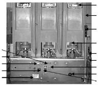
Figure 1 Front view of PowerVac breaker with front cover
1. |
Front cover |
6. |
Manual charge lever |
2. |
Cover mounting bolts |
7. |
Counter |
3. |
Manual trip button |
8. |
Spring charge indication |
4. |
Manual close button |
9. |
Closing spring gag access |
5. |
Nameplate |
10. |
Open/Close indicator |
The circuit breaker has been shipped in the “CLOSED” position.
After removing packing material, open the breaker by pushing in firmly on the manual trip button (item 3, Figure 1), while keeping hands away from moving parts, and verify that the operation counter advances one count.
Closing and opening springs are now in their discharged positions. Check this by first pressing the manual close button, then the manual trip button. The indicator flags on the front of
6
Figure 2 Rating interference plate
1.Rating interference plate
2.Lifting locations (3/4” dia. hole at all four corners)
An option available is the combination 1200/2000 ampere breaker, which can be used in either a 1200 or 2000 ampere compartment. The rating interference plate must be adjusted to match the current rating of the compartment. This adjustment is done by positioning the outer interference plate so that the edge of the plate lines up with the current indicated on the label attached to the breaker just above the rating interference plate.
4.2.2 Closing spring interlock
This racking-track operated interlock (item 4, Figure 20) prevents racking into or out of the metalclad compartment a breaker that has the closing spring charged. This action is accomplished by a roller on the right side of the breaker. Mechanism, which contacts the racking mechanism and discharges the closing spring, unless the breaker is in the “DISCONNECT/TEST” position or the “CONNECT” position in the metalclad compartment. This interlock also opens the CL/MS switch in the motor circuit to prevent electrical charging of the closing spring when the breaker is between the “DISCONNECT/TEST” and “CONNECT” position in the metalclad compartment.
4.2.3 Negative Interlock
The function of this racking-track operated interlock (item5, Figure 19) is to remove the trip latch from the trip roller thereby preventing a closing operation. The interlock also opens the LCS switch in the closing circuit thereby removing the close circuit power. The negative trip interlock is functional while the beaker is being moved between the
“DISCONNECT/TEST” and “CONNECT” position and upon withdrawal from the metalclad compartment.
4.2.4 Positive Interlock Bar
This interlock will prevent the racking of a closed breaker into or out of a metalclad compartment. A linkage connected to the cross shaft extends a détente angle (item 3, Figure 19) out through the left side of the mechanism frame when the breaker contacts are in the closed position. If the breaker is in the “CONNECT” or “DISCONNECT/TEST” position in the metalclad the détente angle locks into the racking mechanism to prevent access to the hex section of the racking screw.
4.2.5 Closing Spring Gag Interlock
The interlock is provided to prevent a breaker that has a gagged closing spring from entering a metalclad unit. This function is accomplished by projecting an angle (item1, Figure 19) out of the left front side of the mechanism when the closing spring is gagged. This angle will interfere with the racking mechanism and block entry into the metalclad unit when the Closing Spring Gag Access Door is open.
7
SECTION 5—Operation
5.1—General
The PowerVac® vacuum circuit breaker uses sealed vacuum power interrupters to establish and interrupt a primary circuit. Primary connections to the associated metalclad switchgear are made by horizontal bars and disconnect fingers, electrically and mechanically connected to the vacuum interrupters. Molded interrupter supports, one per phase on a three-phase circuit breaker, provide mountings for the primary bars, interrupters, current transfer fingers, and heat dissipation fins (where used). The operating mechanism provides direct motion at each phase location in order to move the lower contact of the vacuum interrupters from an open position to a spring-loaded closed position and then back to the open position on command.
The ML-18/18H mechanism (Figure 17) is of the stored-energy type and uses a gearmotor to charge a closing spring. During a closing operation, the energy stored in the closing spring is used to close the vacuum interrupter contacts, compress the wipe springs which load the contacts, charge the opening spring, and overcome bearing and other friction forces, The energy then stored in the wipe springs and opening spring will open the contacts during an opening operation.
Closing and opening operations are controlled electrically by the metalclad switchgear or remote relaying. Mechanical control is provided by manual close and trip buttons on the circuit breaker. The closing spring may be manually charged, and a method for slow-closing the primary contacts is available. The mechanism will operate at the ac or dc voltage indicated on the circuit breaker nameplate.
5.2—Close Spring Charging
Figure 17 shows a front view of the ML-18 in a schematic form. The primary contacts are open and the closing spring is charged. The closing spring charging system consists of a closing spring
(item 1, view B) mounted on the left side of the breaker and the electrical charging system mounted on the right side of the breaker. Both components are fastened to the cam shaft (item 2, view B). A manual charging system (item 3, view A) is provided so that the mechanism can be slow closed and the closing spring can be charged if there is a loss of electrical control power.
Spring charging is accomplished electrically by a rotating eccentric on the output shaft of the gear motor driving pivoted charging arms (item 4, view C) which oscillate about the centerline of a ratchet wheel (item 5, view C). A driving pawl (item 6, view C), mounted within the charging arms, oscillates with the charging arms. Starting from its rear-most position, as the charging arms rotate forward, a spring forces engagement of the driving pawl with a tooth of the ratchet wheel. The ratchet wheel is advanced by the rotating charging arms and pawl assembly. Advancement of one tooth spacing is provided for each oscillation of the system. The ratchet motion is restricted to one direction by a spring-loaded holding pawl that prevents the ratchet wheel from going backwards as the charging arms oscillate back to pick up the next tooth. Thirteen complete cycles of the charging arms are needed for a full charge of the closing spring. The efficient, compact gear motor accomplishes this action in about two seconds. When the charging cycle is complete, the ratchet wheel is positioned so
8
that a missing tooth is adjacent to the driving pawl and any motor over spin will not drive the ratchet wheel, thus preventing damage to the system.
When the spring is completely charged, the assembly is retained in that position by the close latch, until it is desired to close the circuit breaker.
The closing coil cannot be electrically energized unless the closing spring is completely charged. This action is prevented by the 52/CHG switch in the closing circuit.
The manual charging system (item 3, view A) works directly on the cam shaft where a one-way clutch (item 7, view A), driven by a manual handle, provides rotation of the ratchet wheel.
Manual pumping of the handle advances the ratchet wheel and the holding pawl prevents counter-rotation while the handle is returning for another stroke. Approximately eight complete strokes of the manual handle are required for one complete spring-charging operation. When the spring charge indicator
(item 9, Figure 3) shows “CHARGED”, MANUAL CHARGING MUST BE DISCONTINUED TO AVOID MECHANISM DAMAGE.
1
2
12
3
7
4
4
5
9
8
6
13 11
10
Figure 3 Front view of PowerVac breaker without front cover
1. |
Upper interrupt connection |
8. |
Counter |
2. |
Interrupter support |
9. |
Spring charge indication |
3. |
Operating rod |
10. |
Manual charge lever |
4. |
Racking arm |
11. |
Manual close button |
5. |
Compartment track rollers |
12. |
Secondary disconnect |
6. |
Manual trip button |
|
handle |
7. |
Open/Close indicator |
13. |
Closing spring gag access |
5.3—Closing Operation (Refer to Figure 17)
By either energizing the close solenoid or depressing the manual close button, the close latch (item 8, view C) is rotated, releasing the closing spring (item 1, view B). This
action releases the energy in the closing spring and transmits it to the closing cam (item 9, view D) and closing roller (item 10, view D) and causes the linkage to rise until the prop (item 11, view D) can slip under the close roller (item 10, view D) and hold the linkage in place. As the linkage moves, the output crank
(item 12, view D) rotates the cross shaft (item 13, view D) which in turn rotates the phase bell cranks and compresses the two opening springs (item 15, view E) on poles 1 and 3, this closes the vacuum interrupters, and compresses the wipe springs (item 16, view E) on each pole.
The rotation of the cross shaft (item 13, view D) also changes the auxiliary switch (item 7, view D) position. The position flag on the front panel will then indicate “CLOSED”. After the breaker
is closed, the charging motor is again energized and the closing spring is charged as described under “CLOSED SPRING CHARGING”. Spring charging is possible when the breaker is in the closed position because the linkage is held in place by the prop.
5.4—Opening Operation (refer to Figure 17)
By either energizing the trip solenoid or depressing the manual trip button (item 23, view B), the trip latch (item 19, view D) is rotated, permitting the linkage to collapse and the vacuum interrupter contacts to open under the force of the wipe springs (item 16, view E) and opening springs (item 15, view E). At the end of the opening stroke, the center phase wipe spring assembly hits a stop block on the frame that limits overtravel and rebound. Rotation of the cross shaft from the closed to the
open position operates the auxiliary switch (item 17, view D) which opens the trip coil circuit. If the closing spring has been recharged, the linkage will be reset and the trip latch will be in place on the trip roller, ready for another closing operation.
5.5—Trip-free Operation
The linkage is mechanically trip free in any location on the closing stroke. Electrically energizing the trip coil while closing will, after the auxiliary switch contacts change position, rotate the trip latch and permit the circuit breaker to open fully.
The linkage will reset as in a normal open operation, and the closing spring will recharge as described under SPRING CHARGING.
SECTION 6—Electric Control circuit
A typical PowerVac® circuit breaker ML-18 or ML-18H mechanism wiring diagram is shown in Figure 16. Check the wiring diagram supplied with the actual circuit breaker for its wiring.
The close spring-charging motor circuit is established through the CL/MS (close latch monitor switch) switch if the close latch is reset and the SM/LS (spring motor limit switch) if the closing spring is discharged. When the closing spring is charged, the SM/LS interrupts the circuit.
The IL/MS switch is connected to sense position of negative interlock. When the breaker is racked between the connect and disconnect position, the negative interlock roller is depressed as a result the IL/MS switch is open and does not allow the motor to charge the closing spring. Once the breaker is rack in the switch closes allowing the spring charge motor to charge the closing spring.
The close coil circuit is established through two normally closed
52Y relay contacts, and the latch-checking switch LCS, if the trip latch is reset. An auxiliary switch contact 52b is also in series with the close coil and closes when the breaker is
open and opens when the breaker is closed. During a close operation, cam rotation closes the SM/LS contact allowing the
52Y relay to be energized; opening its contacts in the close coil circuit and sealing itself in through one of its own contacts to the close signal. This seal-in action prevents re-closing on a sustained close command as the close signal must be removed to drop out the Y relay, and reestablish the close circuit, thereby providing an anti-pump feature.
Circuit breaker mounted auxiliary switch contacts not used in the control circuit are bought out for control and indication functions. The metalclad equipment may provide a breaker operated stationary auxiliary switch for additional contacts (3, 6 or 10 stages are available.
SECTION 7—Mechanical Checking and Slow Closing
7.1—Visual Inspection
Visually inspect the circuit breaker for any signs of damage or loose hardware.
7.2—Closing Spring Charging
Manually charge the breaker closing spring using the charging handle provided (item 1, Figure 4). The closing spring is charged by a ratcheting mechanism that advances by one ratchet tooth at a time. When the spring is fully charged and the spring load is held by the closing latch, the spring indicator (item 3, Figure 1) will change from “DISCHGD” to “CHARGED”, and a positive snap will be heard as the spring travels over center.
CAUTION: AFTER THE SPRING IS COMPLETELY CHARGED,
AS INDICATED IN FIGURE 4, FURTHER FORCING CHARGING
HANDLE MAY CAUSE DAMAGE TO THE CLOSING LATCH AND
ITS ASSOCIATED PARTS.
3
1
2
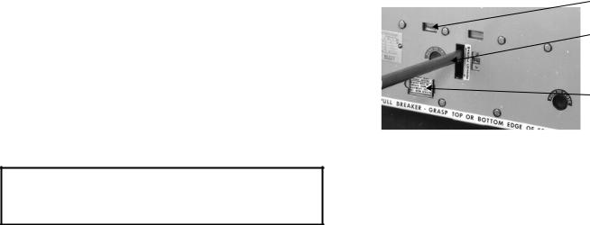
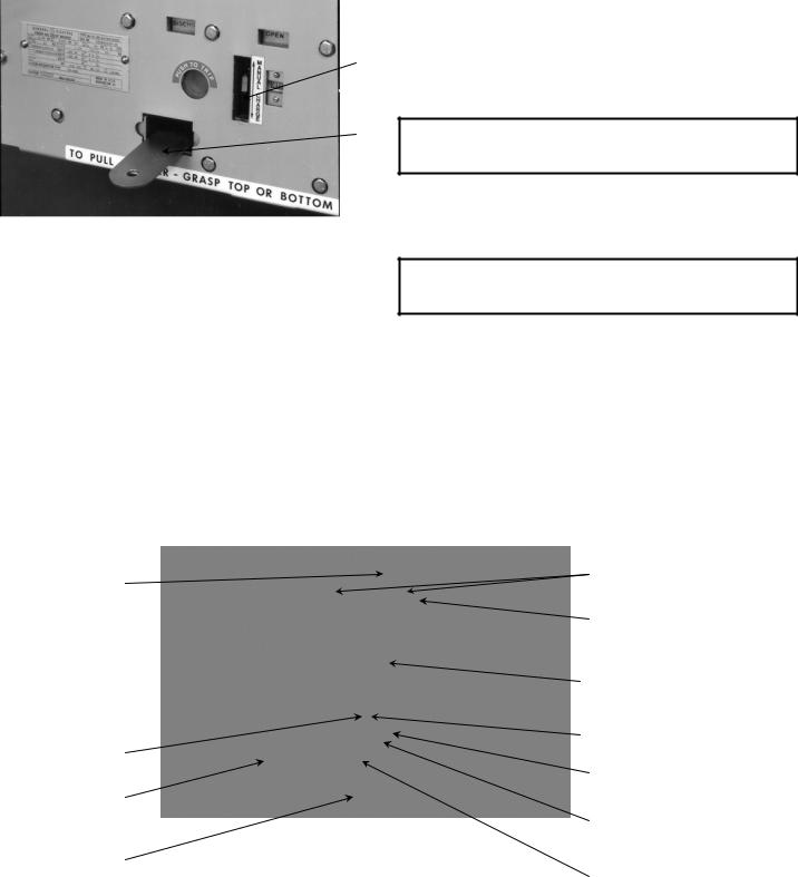
Figure 4 Manual charging
1.Manual charging handle
2.Close spring gag hole (Shown in closed position)
3.Spring charge indication
9
2
1
Figure 5 Gag plate
1 -- Closing spring gag plate
2 -- Manual charging lever
7.3—Closing Spring Gag
Insert the closing spring gag plate (item1, Figure 5) by opening the closing spring gag hole cover and inserting the tip of the gag plate between the end of the spring and the spring guide and engaging the détentes on the gag plate into the slots in the closing spring guide. Note that when the closing spring guide is charged for gagging, an interference angle is exposed on the left side of the breaker (item 3, Figure 19). With the closing spring in the gagged position, this angle will provide interference preventing use of the lift truck and racking of the breaker element. No attempt should be
made to alter, modify or otherwise make inoperative this safety feature. With the gag plate in position, depress the manual close button. This action will partially discharge the closing
10
5
11
1
spring and also partially close the vacuum interrupter contacts. Do not energize the secondary control circuit at this time.
7.4—Slow Closing
To manually slow close the breaker contacts, install the closing spring gag, as described above, and push the manual close button (item 11, Figure 3).
CAUTION: FAILURE TO PUSH THE CLOSE BUTTON BEFORE CONTINUING THE SLOW CLOSE PROCEDURE WILL CAUSE DAMAGE TO THE MECHANISM.
After pushing the manual closing button, put the manual charge handle on the manual charge lever and move the handle up and down. The breaker will be fully closed when the spring charge indicator shows “CHARGED”.
CAUTION: WITH THE GAG PLATE INSTALLED, THE BREAKER CLOSED, AND OPENING SPRINGS CHARGED, THE BREAKER CAN BE TRIPPED AT FULL SPEED.
7.5—Gag Plate Removal
To remove the gag plate, the closing spring must be fully charged. If the spring charge indicator does not show
“CHARGED” in the window, manually charge the spring until it does. Lift up and push in on the gag plate to clear the détentes on the gag plate from the slots in the closing spring guide. While holding the gag plate up, remove it from the opening. Close the gag hole cover. For safety, first close the breaker by depressing the manual “CLOSE” button and then depress the manual “TRIP” button. All stored energy is now removed from the breaker.
9
8
7
6
4
3
2
Figure 6 Operating rod assembly
1. |
Wipe spring |
5. |
Lock washer |
9. |
Clamp screws |
2. |
Wipe indicator (ML 18 only) |
6. |
Hexagon projection |
10. |
Interrupter movable contact rod |
3. |
Erosion disk |
7. |
Operating rod insulator |
11. |
Reference arm |
4. |
Lock nut |
8. |
Coupling clamp |
|
|
10
SECTION 8—Dimensional Checks
With the breaker closed and the gag plate installed, perform the following dimensional checks.
measure with a feeler gauge and record the distance between the bellville washer and the trunion between the bell crank arms.
8.1—Primary Contact Erosion
In the closed position, the erosion disk (item 3, Figure 6) below the operating rod insulator is aligned with a reference arm (item11, Figure 6) on new interrupters. As contact erosion occurs, the erosion disk will move upward from alignment with that reference arm. When erosion reaches 1/8 inch, the PowerVac® interrupters should be replaced. DO NOT RE-ADJUST THE ALIGNMENT OF THE EROSION INDICATOR ARM EXCEPT WHEN INSTALLING A NEW VACUUM INTERRUPTER.
8.2—ML-18 Wipe Spring Compression
With the breaker closed and the closing spring gagged, measure with a feeler gauge and record the distance between the top of the wipe indicator and the bottom of the erosion disk for each phase (see Figure 27, Dimension W). Trip the breaker with the closing spring gag plate still installed and measure and record the distance between the wipe indicator and erosion disk. Subtract the closed position measurement from the open position measurement. The result is the amount of wipe on each individual pole. The wipe is to be greater than 0.075 inch. Adjustment is not required until wipe is 0.075 inch or less. If adjustment is required see WIPE ADJUSTMENT in MECHANICAL ADJUSTMENT section.
The ML-18 and ML-18H mechanisms are furnished with very low gradient wipe springs so that adjustment is not a precision operation and considerable loss of wipe can be tolerated without affecting performance.
8.3—ML-18H Wipe Spring Compression
With the breaker closed and the closing spring gagged,
Figure 7 Contact gap
8.4—Contact Gap
The method of measuring the contact gap is as follows: With the breaker in the open position, the closing springs charged, and the closing spring gag plate installed, apply a piece of masking tape to the surface of the operating rod insulator as shown in Figure 7. Using a reference block, make a mark on the tape near the top on all three poles. It is also advisable to put a reference mark on the tape to identify to which pole the tape is applied. Remove the closing spring gag plate and close the breaker. Using the same procedure as above, remark the tape. This new mark will be near the bottom of the tape. Trip the breaker, remove the tapes and re-apply them to a flat surface. Measure the distance between the two lines. A caliper will give an accurate reading of the contact gap,
Dimension G: The gaps must be between the 0.60 inch maximum at the center pole and 0.54 inch minimum at the outer poles. It is not necessary that all readings correspond. A properly adjusted breaker will have more gap and wipe on the center pole than on the outside poles.
8.5—Coil Plunger Gap
The close coil and trip coil plunger gap dimensional checks are made in the operating mechanism which is accessible from the bottom. To accommodate these checks, the breaker should be turned on its right side resting on two-by-four wood blocks. DO NOT use the portable breaker lift truck.
CAUTION: DO NOT REST UPON OR ALLOW ANYTHING TO COME IN CONTACT WITH THE CLOSING SPRING DISCHARGE ROLLER (item 4,Fig. 20) ON THE RIGHT SIDE OF THE MECHANISM.
1
1.2X4 wood blocks
Figure 8 Breaker turned on right side
11
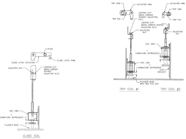
8.5.1—Close Coil Plunger Gap
The close coil plunger gap and correct setting is shown in Figure 9. The operation check and adjustment procedure for the coil plunger will start with the close spring discharged, and verification that the plunger moves freely over its full stroke inside the coil. To check the closing coil plunger gap the breaker should be open and the closing spring charged and gagged. The measurement is made by first depressing the close plunger button until resistance is felt, this accounts for the free travel of the armature. The gap “T” measurement is best made using a ‘go/no-go’ gauge. Refer to figure 9 for gauge details. With the armature depressed until resistance is felt the ‘go’ gauge must fit between the coil housing and the surface of the black PVC cap covering the steel plunger base. With the armature in the same position the ‘no-go’ gauge must not fit between the coil housing and the plunger base. The adjusting nut shown in Figure 9 is used to change this measurement.
ML-18 Breakers with type designation -0, -1 & -2 T= 0.25” to 0.30”
ML-18 Breakers with type designation -3. T= 0.35” to 0.40”
ML-18H Breakers with type designation -0. T= 0.35” to 0.40”
Figure 9 Close coil plunger gap
8.5.2—Trip Coil Plunger Gap
The trip coils #1 and #2 plunger gap and correct setting is shown in Figure 10. The operation check and adjustment procedure for the coil plunger will start with the breaker in the open position and the closing spring in the charged condition and verification that the plunger moves freely over its full stroke inside the coil. This verification is also required for the second trip coil when supplied. To check the trip coil plunger gap the breaker must be closed with the closing spring discharged. The measurement is made by first depressing the trip plunger button until resistance is felt, this accounts for the free travel of the armature. The gap ‘T’ measurement is best made using a ‘go/no-go’ gauge with the ‘go’ end having a thickness of .200 inches and the ‘no-go’ end with a thickness of .251 inches. With the armature depress until
resistance is felt the “go” gauge must fit between the coil housing and the surface of the red PVC cap covering the steel plunger base. With the armature in the same position the “nogo” gauge must not fit between the coil housing and the plunger base. The adjusting nut shown in Figure 10 is used to change this measurement. The same procedure is used for measurement and adjustment of trip coil #2.
Plunger Gap T =. 250+.000/-.050
Figure 10 Trip coil plunger gap
8.6—Control Switch Adjustment
Adjustment of various control switches is done as follows.
8.6.1 LCS and SM/LS Switch Adjustment
The breaker is to be in the open position with the opening and closing spring discharged. This results in the control switch plungers being in the depressed position. The switches to be checked are shown in Figure 11. On the LCS and the SM/LS &CHG switch, the plunger rod is to be flush or slightly recessed (1/32”) within the rear of switch body. This is a visual check.
8.6.2 CL/MS Switch Adjustment
The adjustment of the CL/MS on ML-18 models with type-3 designations and ML-18H models with Type-0 designation is set at the factory and no adjustment is required. Replacement of the CL/MS switch or removal of the angle mounting bracket will require re-adjustment of this switch for correct operation of breaker’s track interlock and close latch. The adjustment will insure that the switch contacts will not close before the close latch is in its re-set position. To achieve this condition shims are required between the CL/MS switch housing and the plunger spacer. Insert shims until the CL/MS contacts do not close when the close latch is in the reset position. Then remove .005inch shim to allow the switch contacts to close just as the close latch reaches the re-set position. This will provide the proper timing between the
CL/MS switch and the close latch.
The adjustment of the CL/MS on ML-18 models with type –0,
-1 and -2 designations is set at the factory. Should adjustment
12

be required, adjust the wiring terminals and set the plunger dimension from .99 to 1.01 from its mounting bracket as shown in Fig.11.
IL/MS SWITCH
NEGATIVE
INTERLOCK
BAR
STACK SWITCH
8.6.3 IL/MS Switch adjustment
The nut should be adjusted to fully extend the plunger.
AUXILIARY
SWITCH
LCS SWITCH
CLMS SWITCH
ML 18 TYPE –0, -1, & -2
SHIM PLACEMENT
CLMS SWITCH
ML 18 TYPE –3
ML 18 H TYPE -0
Figure 11 Control Switches
13

SECTION 9—Electrical Checks
Electrical checking consists of electrical breaker operation primary and secondary wiring high-potential testing (if required), primary circuit resistance (if required), PowerVac® interrupter high-potential testing, and insulation resistance to ground.
9.1—Electrical Operation
To check the electrical operation, attach a secondary test coupler to the circuit breaker connector. Check the control voltage on the nameplate and close and open the breaker several times.
CAUTION: REPEATED OPERATIONS AT A RATE EXCEEDING TWO PER MINUTE MAY CAUSE CHARGING MOTOR OVERHEATING AND FAILURE.
Leave the circuit breaker in an open and spring discharged condition after checks are complete and refer to metalclad instruction book GEK-39672 before inserting the circuit breaker into a metalclad unit. Reinstall the front cover if it has been removed.
9.2—High-Potential Test
If high potential tests to check the integrity of the primary insulation is required, the AC high potential test described below is strongly recommended. DC high potential testing is not recommended. The following procedure must be adhered to.
CAUTION: IF DC HIGH POTENTIAL TESTING IS REQUIRED, THE DC HIGH POTENTIAL MACHINE MUST NOT PRODUCE PEAK VOLTAGES EXCEEDING 50 kV.
NOTE: Always recheck with an AC tester if initial results are questionable.
9.2.1 Primary Circuit
The breaker should be hipotted with the breaker closed. An AC hipot machine capable of producing the test voltages shown below may be used to hipot the breaker phase to phase and phase to ground.
BREAKER VOLTAGE |
AC TEST VOLTAGE |
|
4.16 KV |
14 KV |
|
|
||
|
||
7.2 KV |
27 KV |
|
13.8 KV |
27 KV |
|
The machine should be connected with its output potential at zero and the voltage increased at 500 volts per second to the test voltage and that voltage maintained for 60 seconds. The voltage should then be returned to zero and the test leads removed from the circuit and the breaker discharged to ground.
NOTE: Do not exceed the test voltage indicated for the applicable breaker voltage rating. If the test should experience a failure, STOP, turn off the test set and discharge the breaker circuit.
1.Check the test set up and leads for connection errors.
2.Wipe down the breaker to remove any moisture, dust and contamination.
3.Retest the breaker at the proper test voltage.
14
9.2.2 Secondary Circuit
Prior to hipotting the breaker secondary circuit, disconnect the motor leads and thread a wire connecting all secondary disconnect pins, except #24, the ground pin. Connect the hipot machine from this wire to ground. Increase the voltage to 1125 volts (rms) 60 Hz and maintain for 60 seconds.
Reduce the voltage to zero and remove the hipot machine from the circuit. Remove the wire connecting the secondary disconnect pins and reconnect the motor leads.
9.3—Primary Circuit Resistance
A resistance check of the primary circuit may be made with the breaker closed. Use a low resistance measuring
instrument rated 100 amperes which measures in microhms. The 100 ampere reading should be 30 to 60 microhms for a 1200 amp. Breaker, 25 to 50 for a 2000 ampere breaker. and 5 to 25 microhms for a 3000 ampere breaker when connected across the primary bars on the breaker side of the disconnect fingers. Do not connect directly to the disconnect fingers as errors may occur due to finger spring pressure.
9.4—Vacuum Interrupter Integrity Test
NOTE: Use of a DC hipot is not recommended, but can be used for quick field checks only. DC testers frequently yield false negative test results due to the capacitive component of the vacuum interrupter during DC testing. In addition, most lightweight DC testers have a very low leakage current trip setting. Always recheck with an AC tester if initial results are questionable. Prior to performing any vacuum interrupter integrity test, the outside (external surface) of the vacuum interrupters should be wiped clean of any contaminates with a non-linting cloth or industrial type wiper. This is critical: the entire external surface is to be completely free of all dirt, debris, dust, oil, etc.
CAUTION: X-RADIATION WILL BE PRODUCED IF AN ABNORMALLY HIGH VOLTAGE IS APPLIED ACROSS A PAIR OF ELECTRODES IN A VACUUM. X-RADIATION WILL INCREASE AS VOLTAGE INCREASES AND/OR AS CONTACT SEPARATION DECREASES. ONLY TEST A CORRECTLYADJUSTED CIRCUIT BREAKER.
DURING A HIGH POTENTIAL OR A VACUUM INTEGRITY TEST, ANY X-RADIATION WHICH MAY BE PRODUCED WILL NOT BE HAZARDOUS AT A DISTANCE SAFE FOR HIGH
POTENTIAL TESTING, IF THE TEST IS CONDUCTED AT THE
RECOMMENDED VOLTAGE AND WITH THE NORMAL OPEN CIRCUIT BREAKER GAP.
DO NOT APPLY VOLTAGE THAT IS HIGHER THAN THE RECOMMENDED VALUE. DO NOT USE CONTACT SEPARATION THAT IS LESS THAN THE RECOMMENDED OPENPOSITION BREAKER CONTACT GAP.
A vacuum integrity test of the interrupter is required to ensure that no loss of vacuum has occurred. The vacuum integrity test is performed using an AC hi-potential tester. This test of the vacuum interrupter will determine its internal dielectric condition and vacuum integrity. With the breaker open,
 Loading...