


GPS 4848-100
Table of contents
 Loading...
Galaxy Power System 4848/100
with Dual Rectifier Shelf
and 595LT Rectifiers S2:0 and later
(GPS 4848/100)
H569-434
Notes: Refer to the Millennium II Product Manual 167-792-181 for Galaxy
Millennium II installation and setup.
Instructions in this manual reference installation and setup of the
Galaxy Millennium Controller.
Refer to User’s Guide Issue 3 for 595LT Series Rectifiers prior to S2:0.
User’s Guide
Select Code 167-792-166
Comcode 108994042
Issue 5 September 2011


User’s Guide
Select Code 167-792-166
Comcode 108994042
Issue 5
September 2011
Galaxy Power System 4848/
100 with Dual Rectifier Shelf
and 595LT Rectifiers S2:0 and later
(GPS 4848/100)
Notice:
The information, specifications, and procedures in this manual are
subject to change without notice. Lineage Power assumes no
responsibility for any errors that may appear in this document.
Note: Instructions in this manual reference installation and setup of the Galaxy
Millennium Controller. For Galaxy Millennium II installation and setup,
refer to the Millennium II Product Manual 167-792-181.
Refer to User’s Guide Issue 3 for 595LT Series Rectifiers prior to S2:0.
© 2011 Lineage Power
All International Rights Reserved
Printed in U.S.A.
H569-434


Galaxy Power System 4848/100 with Dual Rectifier Shelf
Table of Contents
1 Introduction
GPS 4848/100 1-1
Overview 1-1
Related Documentation 1-1
Illustration 1-2
Safety 1-3
Electromagnetic Compliance 1-3
CE Marking 1-3
Telcordia 1-3
Customer Service Contacts 1-4
Customer Service, Technical Support, Product Repair and
Return, and Warranty Service 1-4
Customer Training 1-4
Downloads and Software 1-4
2 System Description
Overview 2-1
Block Diagram 2-1
System Components 2-2
Bonding Network 2-2
Facility 2-2
Architecture 2-3
Introduction 2-3
Distributed 2-3
Centralized 2-5
Standard 2-7
Non-Traditional 2-7
3 Galaxy Millennium Controller
Overview 3-1
Mounting Location 3-1
Circuit Boards 3-1
Reference Material 3-1
Controller Product Manual 3-1
RPM System Product Manual 3-1
User Interface and Display 3-2
Front Panel 3-2
Default Display 3-2
LEDs 3-3
Issue 5 September 2011 Table of Contents - 1

Galaxy Power System 4848/100 with Dual Rectifier Shelf
Pushbutton Controls 3-3
Test Jacks 3-4
4 Rectifiers
595 Series 4-1
Overview 4-1
Front Panel Display 4-2
Power Switch 4-2
Status Indicators 4-2
Current Display 4-2
Lamp Test 4-2
Illustration 4-2
Features 4-3
Output Voltage Adjustment 4-3
Output Current “Walk-in” 4-3
Electronic Current Limit 4-3
Selective High Voltage Shutdown (SHVSD) 4-3
Backup High Voltage Shutdown (BHVSD) 4-3
Restart 4-3
Output Circuit Breaker 4-3
Fan Alarm and Control 4-3
Thermal Alarm 4-4
Controller Communications Alarm 4-4
Autonomous Operation of the Rectifier 4-4
Connectorized 4-4
“Forced” Load Sharing 4-4
5 AC Input Panels
Overview 5-1
AC Service 5-1
Illustrations 5-1
6 Battery Connection Panels
Overview 6-1
Introduction 6-1
Distributed Architecture 6-1
Centralized Architecture 6-1
Illustrations 6-1
7 DC Distribution Panels
Overview 7-1
2 - Table of Contents Issue 5 September 2011

Galaxy Power System 4848/100 with Dual Rectifier Shelf
Function 7-1
Illustrations 7-1
8 Circuit Boards
Overview 8-1
Function 8-1
Terminal Boards 8-1
Alarm Boards 8-1
Alarm/Terminal Boards 8-1
BLJ Terminal Board 8-1
Bay Interface Card 8-2
Contactor Control Board 8-2
9 Specifications
GPS 4848/100 9-1
Rectifiers 9-4
AC Input Panels 9-6
Battery Connection Panels 9-7
DC Distribution Panels 9-8
10 Safety
11 Maintenance and Replacement
Requirements 11-1
System 11-1
Batteries 11-1
Controller 11-1
Rectifier 11-2
Vacant Rectifier Positions 11-2
Rectifier Fan Assembly 11-2
Replacement Procedures 11-3
Installing or Replacing a Rectifier 11-3
Removing a Rectifier 11-6
Replacing the Rectifier Fan Assemblies 11-7
Testing 11-9
Testing Additional Alarms After Replacing Rectifiers 11-9
Testing Rectifiers and Load Share in Bay Expansions 11-9
Replacement Parts 11-10
System 11-10
Millennium Controller Circuit Boards 11-11
Additional Ordering Information 11-11
Issue 5 September 2011 Table of Contents - 3

Galaxy Power System 4848/100 with Dual Rectifier Shelf
Documentation 11-11
Software 11-11
12 Troubleshooting Preparations
Preliminary 12-1
Introduction 12-1
Safety 12-1
Tools 12-1
Troubleshooting Procedure 12-2
Purpose 12-2
Cabinet Alarm 12-2
System Status 12-3
Alarms Menu 12-3
Troubleshooting Tables 12-3
Identifying Problems 12-3
Reference Figures 12-4
Figure Numbers and Titles 12-4
Millennium Controller 12-4
Rectifier 12-6
Low Voltage Battery Disconnect 12-7
AC Input 12-8
AC Input 12-9
DC Distribution 12-10
Low Voltage Load Disconnect 12-11
13 Troubleshooting Millennium Systems
Introduction 13-1
In This Section 13-1
Preparation 13-1
Technical Assistance 13-1
Troubleshooting Tables 13-2
Organization 13-2
Table Reference 13-2
Rectifier Display Messages and LEDs 13-2
Millennium Controller Display 13-3
AC Alarm LED 13-3
BATT Alarm LED 13-4
CTRL Alarm LED 13-5
DIST Alarm LED 13-9
RECT Alarm LED 13-10
BD and RM Alarm LEDs, or No LED 13-15
4 - Table of Contents Issue 5 September 2011

Galaxy Power System 4848/100 with Dual Rectifier Shelf
14 Product Warranty
Revision History
Issue 5 September 2011 Table of Contents - 5

Galaxy Power System 4848/100 with Dual Rectifier Shelf
6 - Table of Contents Issue 5 September 2011

Galaxy Power System 4848/100 with Dual Rectifier Shelf
List of Figures
Figure 1-1: GPS 4848/100 With Millennium Controller 1-2
Figure 2-1: Block Diagram of the GPS 4848/100
(Distributed Architecture) 2-1
Figure 2-2: Distributed Architecture 2-4
Figure 2-3: Distributed Architecture Initial and Growth Cabinets
2-4
Figure 2-4: Centralized Architecture 2-5
Figure 2-5: Centralized Architecture Cabinets 2-6
Figure 2-6: Non-Traditional Cabling Arrangements 2-7
Figure 3-1: Galaxy Millennium Controller Front Panel 3-2
Figure 4-1: Rectifier Front Panel 4-2
Figure 5-1: H569-434 G20/320/420 (ED83142-30 G3)
208/240V AC Input Circuit Breaker Panel - 4 Rectifier 5-2
Figure 5-2: H569-434 G21/23/321/323/421 (ED83142-30 G4)
208/240/480V AC Input Circuit Breaker Panel - 6 Rectifier 5-2
Figure 5-3: H569-434 G334/335 (ED83142-30 G24/25)
208/240/480V AC Input Circuit Breaker Panel - 12 Rectifier 5-3
Figure 5-4: H569-434 G22/322 (ED83142-30 G2)
480V AC Input Circuit Breaker Panel - 4 Rectifier 5-3
Figure 5-5: H569-434 G24/25/26/27/324/325/326/327/330/331
(ED83142-30 G5)
208/240/480V AC Input Terminal Strip Panel - 6 Rectifier 5-4
Figure 5-6: H569-434 G128/129/130/131 (ED83142-30 G18)
208/240/480V AC Input Terminal Strip Panel - 8 Rectifier 5-4
Figure 5-7: H569-434 G328/329/332/333 (ED83142-30 G26)
208/240/480V AC Input Terminal Strip Panel - 14 Rectifier 5-5
Figure 5-8: H569-434 G70/370/470 (ED83142-30 G10)
480V 65kAIC AC Input Circuit Breaker Panel - 4 Rectifier 5-5
Issue 5 September 2011 List of Figures - 1

Galaxy Power System 4848/100 with Dual Rectifier Shelf
Figure 5-9: H569-434 G71/371/471 (ED83142-30 G11)
480V 65kAIC AC Input Circuit Breaker Panel - 6 Rectifier 5-6
Figure 6-1: H569-434 G30 (ED83143-31 G32)
Battery Connection Panel 6-2
Figure 6-2: H569-434 G31 (ED83143-31 G31)
Battery Connection Panel 6-2
Figure 6-3: H569-434 G32/32A (ED83143-31 G30/30A)
Battery Connection Panel 6-3
Figure 6-4: H569-434 G34 (ED83143-31 G41)
Battery Connection Panel 6-3
Figure 6-5: H569-434 G35 (ED83143-31 G42)
Battery Connection Panel 6-4
Figure 6-6: H569-434 G37/38 (ED83143-31 G60/61)
Battery (OLE) Connection Panel 6-4
Figure 6-7: H569-434 G80/81/82 (ED83143-31 G31/43)
Battery Connection Panel 6-5
Figure 6-8: H569-434 G86/87 (ED83143-31 G63/64)
Battery Connection Panel 6-6
Figure 6-9: H569-434 G39 (ED83143-31 G36)
Battery Connection Panel 6-6
Figure 7-1: H569-434 G40/45/50/55 (ED83143-31 G11)
400A DC Distribution Panel 7-2
Figure 7-2: H569-434 G41/46/51/56 (ED83143-31 G12)
400A DC Distribution Panel 7-2
Figure 7-3: H569-434 G42/47 (ED83143-31 G2)
600A DC Distribution Panel 7-3
Figure 7-4: H569-434 G43 (ED83143-31 G1)
1200A DC Distribution Panel 7-3
Figure 7-5: H569-434 G48 (ED83143-31 G5)
1000A DC Distribution Panel 7-4
Figure 7-6: H569-434 G52 (ED83143-31 G53)
600A DC Distribution Panel 7-4
Figure 7-7: H569-434 G53/57 (ED83143-31 G55)
1000A DC Distribution Panel 7-5
2 - List of Figures Issue 5 September 2011

Galaxy Power System 4848/100 with Dual Rectifier Shelf
Figure 7-8: H569-434 G60/61/65/66 (ED83143-31 G71)
600A DC Distribution Panel 7-5
Figure 7-9: H569-434 G67 (ED83143-31 G22)
600A DC Distribution Panel 7-6
Figure 7-10: H569-434 G68 (ED83143-31 G21)
1200A DC Distribution Panel 7-6
Figure 7-11: H569-434 G96 (ED83143-31 G15)
510A DC Distribution Panel 7-7
Figure 7-12: H569-434 G97 (ED83143-31 G16) 14-Position, and
H569-434 G98 (ED83143-31 G17) 22-Position DC Distribution
Panel 7-7
Figure 7-13: H569-434 G54 (ED83143-31 G54) 5-Position DC Dis-
tribution Panel 7-8
Figure 7-14: H569-434 G58 (ED83143-31 G58) 6-Position GMT DC
Distribution Panel 7-8
Figure 7-15: H569-434 G59 (ED83143-31 G56) 2-Position Fuse Dis-
tribution Panel 7-9
Figure 11-1: Installing a Rectifier in a Rectifier Shelf 11-4
Figure 11-2: Rectifier Fan Replacement 11-7
Figure 12-1: Location of Cabinet Alarm Light and Controller 12-2
Figure 12-2: Millennium Controller Display 12-5
Figure 12-3: Millennium Controller Fuses and Circuit Boards 12-5
Figure 12-4: Rectifier Display 12-6
Figure 12-5: Low Voltage Battery Disconnect
Contactor Control Switches 12-7
Figure 12-6: AC Input Panel and Rectifier Positions, 6 Rectifiers
12-8
Figure 12-7: AC Input Panel and Rectifier Positions, 12 Rectifiers
12-9
Figure 12-8: DC Distribution Panel 12-10
Figure 12-9: Low Voltage Load Disconnect Contactor
Control Switches 12-11
Issue 5 September 2011 List of Figures - 3

Galaxy Power System 4848/100 with Dual Rectifier Shelf
4 - List of Figures Issue 5 September 2011

Galaxy Power System 4848/100 with Dual Rectifier Shelf
List of Tables
Table 9-A: Galaxy Power System 4848/100 Specifications 9-1
Table 9-B: 595LT Series S2:x Rectifier Specifications 9-4
Table 9-C: Rectifier Display Messages and LEDs 9-5
Table 9-D: AC Panels 9-6
Table 9-E: Battery Connection Panels 9-7
Table 9-F: DC Distribution Panels 9-8
Table 11-A: GPS 4848/100 Replacement Parts 11-10
Table 11-B: Galaxy Millennium Controller Circuit Boards 11-11
Table 11-C: Product Documentation 11-11
Table 13-A: AC Alarms 13-3
Table 13-B: Battery Alarms 13-4
Table 13-C: Controller Alarms 13-5
Table 13-D: Distribution Alarms 13-9
Table 13-E: Rectifier Related Alarms 13-10
Table 13-F: Miscellaneous Alarms 13-15
Issue 5 September 2011 List of Tables - 1


Galaxy Power System 4848/100 with Dual Rectifier Shelf
1 Introduction
GPS 4848/100
Overview The Galaxy Power System (GPS) 4848/100 provides -48 volt
telecommunications powering solutions in worldwide markets. The
GPS 4848/100 combines 220 and 200-ampere, fan-cooled, switchmode
rectifiers, microprocessor control technologies, battery and load
disconnect/reconnect options, and a comprehensive line of fuse and
circuit breaker dc distribution options in a modular front-access design.
This modularity ensures easy access, simplified installation and
maintenance, and allows the system to expand in capacity and features
as power needs grow.
With 14,080-ampere maximum capacity, distribution flexibility, and
universal ac input capability, the GPS 4848/100 supports switching,
transmission, and wireless applications in central office locations and
environmentally controlled remote sites (huts or vaults). For centralized
architecture, bus bars are available to 14,080A.
Notes This document includes information for 595LT series S2:0 and later
rectifiers. Refer to User’s Guide Issue 3 for 595LT Series Rectifiers
ior to S2:0. For information about 595A and 595B series rectifiers see
pr
the GPS 4848/100 User’s Guide.
595A and 595B series rectifiers (full width, one per shelf) are fully
supported by GPS 4848/100 with Dual Rectifier Shelves.
Related Documentation
Ordering Guide H569-434
Manufacturing Drawings ED83142-30 (AC)
Wiring Diagram T83314-30
User’s Guide 167-792-155
GPS4848/100
ED83143-31 (DC)
J85582C-1 (System)
Issue 5 September 2011 Introduction 1 - 1
Galaxy Power System 4848/100 with Dual Rectifier Shelf
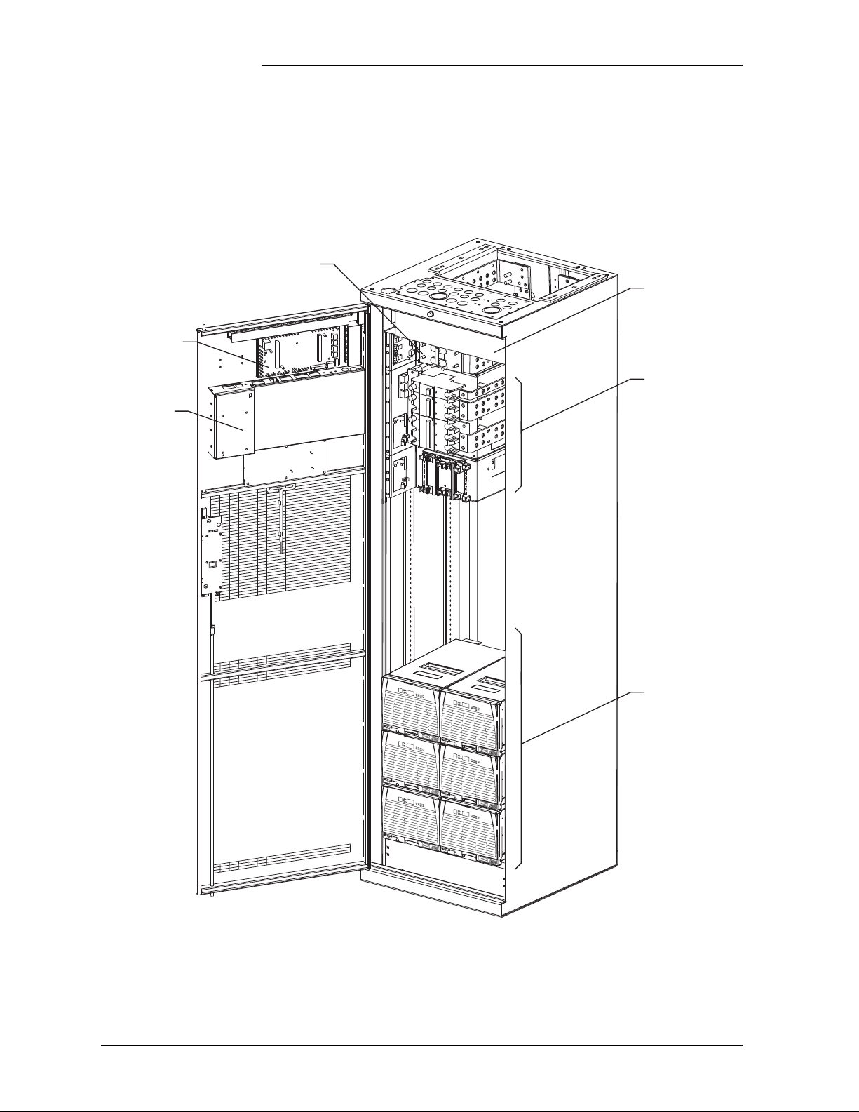
Galaxy
Millennium
Controller
BLJ3
Terminal
Board
Battery Connection Panel
AC Panel
595LT Series
220A Rectifiers
DC Distribution
GPS 4848/100, continued
Illustration Figure 1-1 is an isometric view of the GPS 4848/100 with a Millennium
Controller.
Figure 1-1: GPS 4848/100 With Millennium Controller
1 - 2 Introduction Issue 5 September 2011

Galaxy Power System 4848/100 with Dual Rectifier Shelf
GPS 4848/100, continued
Safety •UL1 Listed (US and Canada): UL Subject 1801 with applicable
sections of UL1950/CSA2 950)
• VDE Licensed to VDE 0805/IEC950/EN60950
Electromagnetic
• Emission:
Compliance
– FCC Part 15 Class B
– EN55022 (CISPR 22) Radiated/Conducted Emission, Class B
• Immunity
– IEC/EN 61000-4-2 ESD level 3 and 4
– IEC/EN 61000-4-3 Radiated Immunity, 10V/m
– IEC/EN 61000-4-4 Electrical Fast transients/Burst, level 4
– IEC/EN 61000-4-5 Lightning Surge, level 4
CE Marking • CE marked per European Union Council Directives:
– Low-Voltage Directive (73/23/EEC) and
– EMC Directive (89/336/EEC) as amended by CE Marking
Directive (93/68/EEC)
Telcordia • GR-63 and GR-1089 NEBS (including Level 3 testing)
• Report by an independent test laboratory - NRTL
1.UL is a registered trademark of Underwriters Laboratories, Inc.
2.CSA is a registered trademark of Canadian Standards Association.
Issue 5 September 2011 Introduction 1 - 3

Galaxy Power System 4848/100 with Dual Rectifier Shelf
Customer Service Contacts
Customer Service, Technical Support, Product Repair and Return, and Warranty Service
For customers in the United States, Canada, Puerto Rico, and the US
Virgin Islands, call 1-800-THE-1PWR (1-800-843-1797). This number
is staffed from 7:00 am to 5:00 pm Central Time (zone 6), Monday
through Friday, on normal business days. At other times this number is
still available, but for emergencies only. Services provided through this
contact include initiating the spare parts procurement process, ordering
documents, product warranty administration, and providing other
product and service information.
For other customers worldwide the 800 number may be accessed after
first dialing the AT&T Direct country code for the country where the
call is originating, or you may contact your local field support center or
your sales representative to discuss your specific needs.
Customer Training Lineage Power offers customer training on many Power Systems
products. For information call 1-972-284-2163. This number is
answered from 8:00 a.m. until 4:30 p.m., Central Time Zone (Zone 6),
Monday through Friday.
Downloads and Software
To download the latest product information, product software and
software upgrades, visit our web site at
http://www.lineagepower.com
1 - 4 Introduction Issue 5 September 2011

Galaxy Power System 4848/100 with Dual Rectifier Shelf
LVLD
DISCHG RTN
LVLD
Control
Board
Rectifiers
DC Distribution
Controller
Return
Bus
(+)
To 48 Volt
Loads
AC Input
Power
48V
Returns
LVBD
BAT BUS
CHG RTN
LVBD
Control
Board
Battery Distribution
Battery (-)
Battery
Shunt
Battery (+)
CO
GND
Sense/Control
Connections
AC Input
Chg
Bus
(-)
2 System Description
Overview
Block Diagram Figure 2-1 shows a basic block diagram of the Galaxy Power System
4848/100. It illustrates the arrangement and interconnections of the
system components from the ac input to the dc output.
Figure 2-1: Block Diagram of the GPS 4848/100
(Distributed Architecture)
Issue 5 September 2011 System Description 2 - 1

Galaxy Power System 4848/100 with Dual Rectifier Shelf
Overview, continued
System Components
The power system accepts alternating current from the commercial
utility or a standby ac power source and rectifies it to produce dc power
for the using equipment. The system’s control and alarm functions
interact with the rectifiers and the office. In addition, the system
provides overcurrent protection and charge, discharge, and distribution
facilities. Battery reserve automatically provides a source of dc power if
the commercial or standby ac fails. Battery reserve can be engineered to
supply dc power for a specific period of time. In normal practice, battery
capacity is sized to provide 3 to 8 hours of reserve time.
AC Input connects the commercial and/or standby ac power sources to
the rectifiers within the system and provides overcurrent protection. In
some applications the ac service is wired directly to the rectifiers and
overcurrent protection is provided at the service panel.
Rectifiers convert an ac source voltage into the dc voltage level required
to charge and float the batteries and to power the using equipment.
Controller provides the local and remote control, monitoring, and
diagnostic functions required to administer the power system.
Batteries provide energy storage for an uninterrupted power feed to the
using equipment during loss of ac input or rectifier failure.
DC Distribution Panel provides overcurrent protection, connection
points for the using equipment, and bus bars used to interconnect the
rectifiers, batteries, and dc distribution.
Battery Connection Panel provides connection points for the battery
strings through battery disconnect fuse, contactors, current monitoring
shunts, and equalize converters.
Bonding Network The GPS 4848/100 system is suitable for installation as part of a
Common Bonding Network (CBN) or an Isolated Bonding Network
(IBN).
Facility The GPS 4848/100 system is suitable for installation in Network
Telecommunication Facilities and locations where NEC applies.
2 - 2 System Description Issue 5 September 2011

Galaxy Power System 4848/100 with Dual Rectifier Shelf
Architecture
Introduction For the GPS 4848/100 system, the basic system components, i.e., ac
input panels, battery connection panels, dc distribution panels, rectifiers,
and controller, can be configured to form two distinct system
architectures: distributed or centralized.
Distributed In this system each cabinet contains ac distribution, dc distribution
panels, battery connection panels, rectifiers, termination points for load
circuits, and a battery shunt. The initial cabinet also contains the system
controller and, as such, it can function as a stand-alone system. The
rectifier output buses are interconnected to permit cabinets to share
current and ensure common voltage references for all system rectifiers.
Because each cabinet is basically a self-contained system, the overall
system capacity can be increased by simply adding cabinet/battery
entities. However, growing the system requires a distinct, dedicated
floor plan.
During normal operation, the readings from the battery shunts are
summed and subtracted from the rectifier current to obtain the system
load current. While the batteries are providing the system load power,
the individual battery shunts may be monitored to determine the status
of the individual battery sections.
Cabinets can be equipped with load and/or battery disconnect/reconnect
contactors. Battery contactors prevent battery damage during deep
discharges by disconnecting batteries. Load contactors can extend the
time critical loads operate on battery discharge by disconnecting
non-critical loads during discharge.
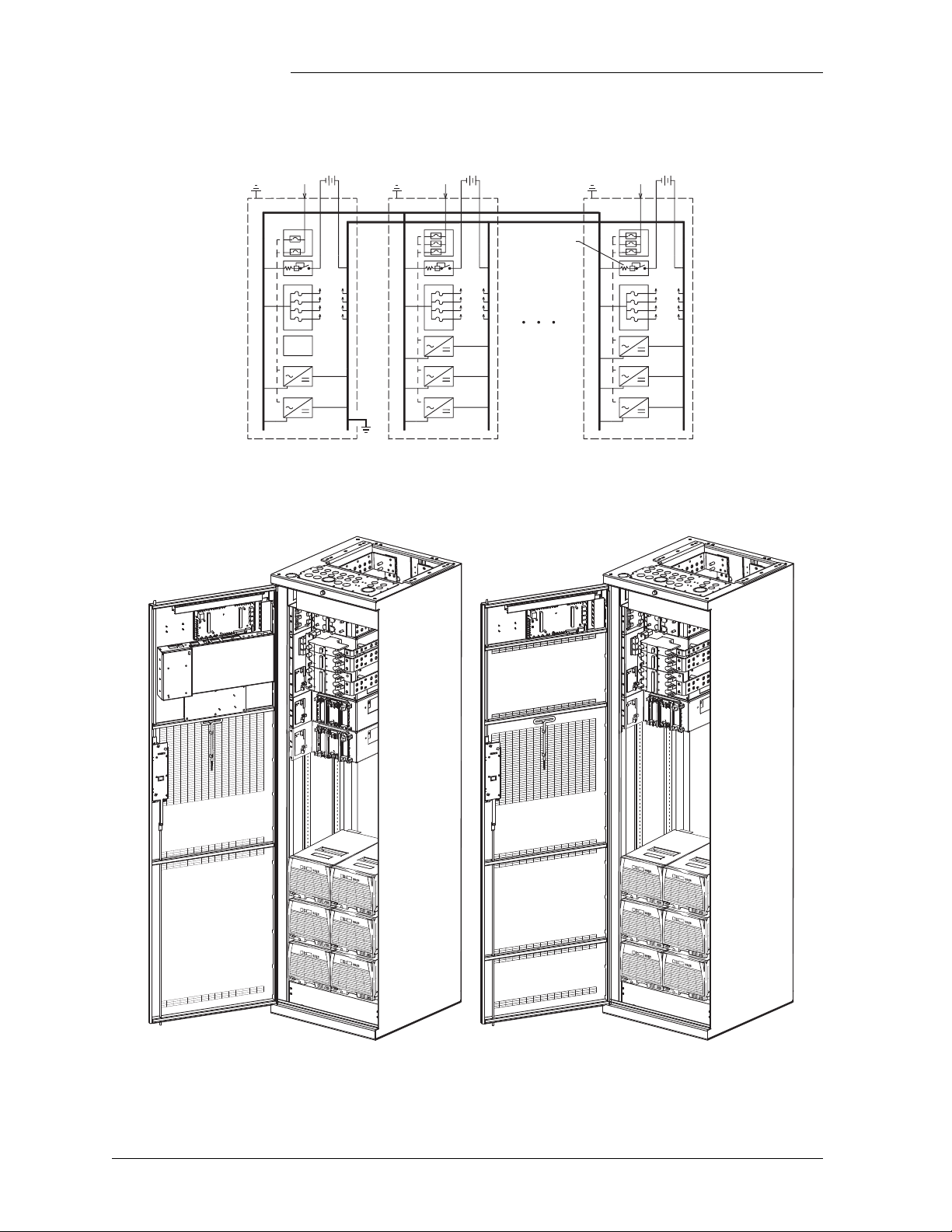
Figure 2-2 shows an example of GPS 4848/100 components configured
in a distributed architecture; Figure 2-3 gives a front view of the
distributed initial and growth cabinets.
Issue 5 September 2011 System Description 2 - 3
Control
and
Monitor
Battery Shunt
To Loads
Battery String
Galaxy Power System 4848/100 with Dual Rectifier Shelf
Initial Cabinet
Growth Cabinet
Architecture, continued
Figure 2-2: Distributed Architecture
Figure 2-3: Distributed Architecture Initial and Growth Cabinets
2 - 4 System Description Issue 5 September 2011
Galaxy Power System 4848/100 with Dual Rectifier Shelf
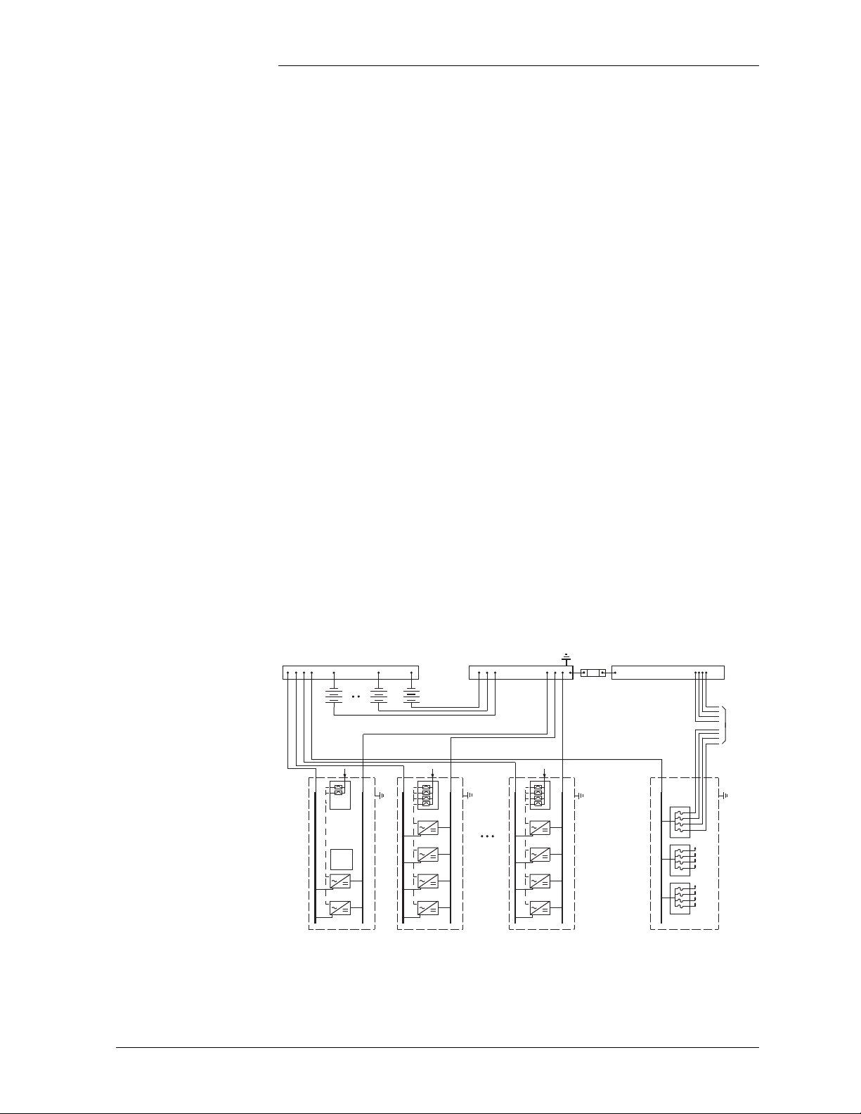
Charge Bus Charge Return Bus Discharge Return Bus
Battery Strings
Plant
Shunt
Control
and
Monitor
Loads
Architecture, continued
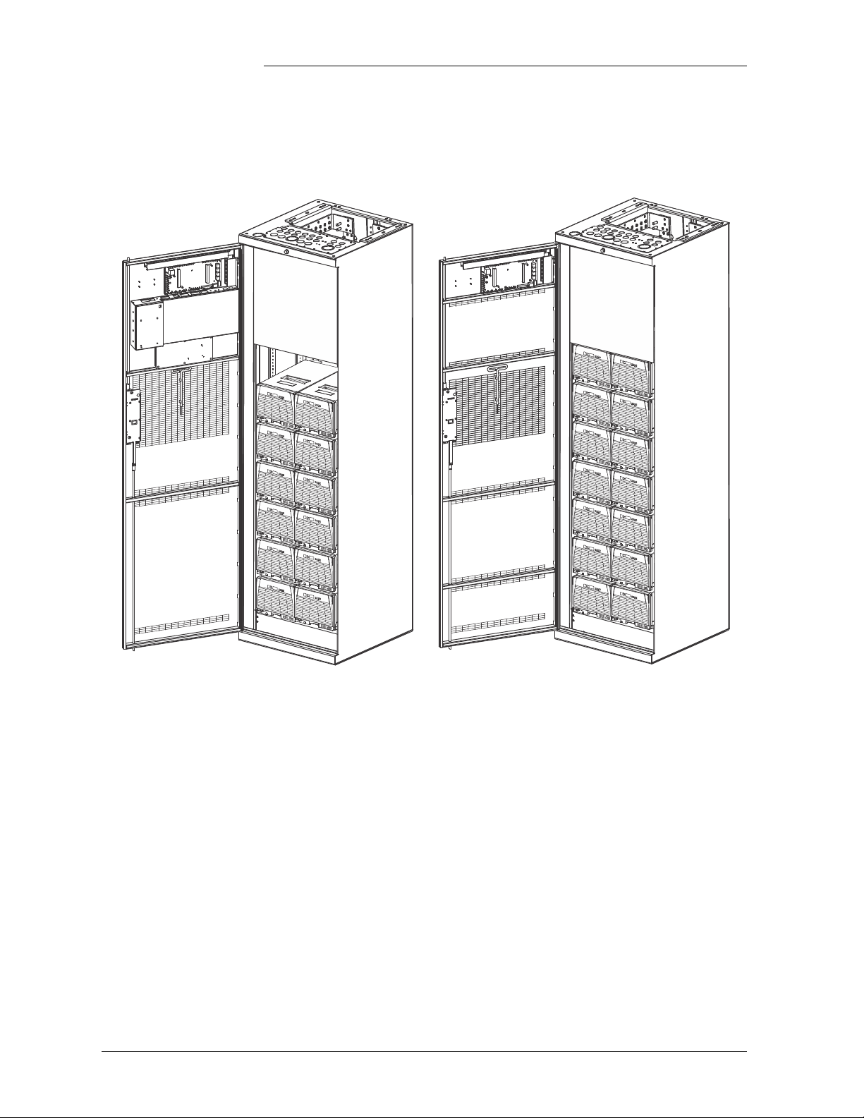
Centralized Figure 2-4 shows GPS 4848/100 components configured in a
centralized architecture; Figure 2-5 provides a view of the centralized
architecture cabinets with and without controller.
Rectifiers, dc distribution panels, and batteries are cabled to external
busbars where a single system shunt is provided to measure total system
load current.
Rectifier cabinets contain ac distribution or ac terminal blocks,
rectifiers, and cable termination points.
DC distribution cabinets contain load protectors, load cable termination
points, and may include load disconnect/reconnect contactors.
The GPS 4848/100 controller may be provided in a dc distribution
cabinet or a rectifier cabinet equipped with ac circuit breakers. The
cabinet with the controller also contains termination points for the
system interconnect cables.
This architecture requires extensive up-front planning to determine the
ultimate system capacity and engineering to size the external busbars
appropriately; however, the system plan is not constrained to dedicated
layouts as required for distributed architecture systems.
Figure 2-4: Centralized Ar
Issue 5 September 2011 System Description 2 - 5
chitecture
Galaxy Power System 4848/100 with Dual Rectifier Shelf
Architecture, continued
Cabinet with Controller
Cabinet without Controller
Figure 2-5: Centralized Architecture Cabinets
2 - 6 System Description Issue 5 September 2011
Galaxy Power System 4848/100 with Dual Rectifier Shelf
AC Input
Battery and
DC Load Leads
AC Input
Battery and
DC Load Leads
AC Input
Battery and
DC Load Leads
"A" Arrangement "B" Arrangement "C" Arrangement
REMOVE
BEFORE
ADDING
SECOND
RECTIFIER
REMOVE
BEFORE
ADDING
SECOND
RECTIFIER
REMOVE
BEFORE
ADDING
SECOND
RECTIFIER
REMOVE
BEFORE
ADDING
SECOND
RECTIFIER
REMOVE
BEFORE
ADDING
SECOND
RECTIFIER
REMOVE
BEFORE
ADDING
SECOND
RECTIFIER
REMOVE
BEFORE
ADDING
SECOND
RECTIFIER
REMOVE
BEFORE
ADDING
SECOND
RECTIFIER
REMOVE
BEFORE
ADDING
SECOND
RECTIFIER
REMOVE
BEFORE
ADDING
SECOND
RECTIFIER
REMOVE
BEFORE
ADDING
SECOND
RECTIFIER
REMOVE
BEFORE
ADDING
SECOND
RECTIFIER
Cabinet Cabling Options
Standard Standard cabinets are designed so that ac, battery, and dc load cables are
run through the top of the cabinet.
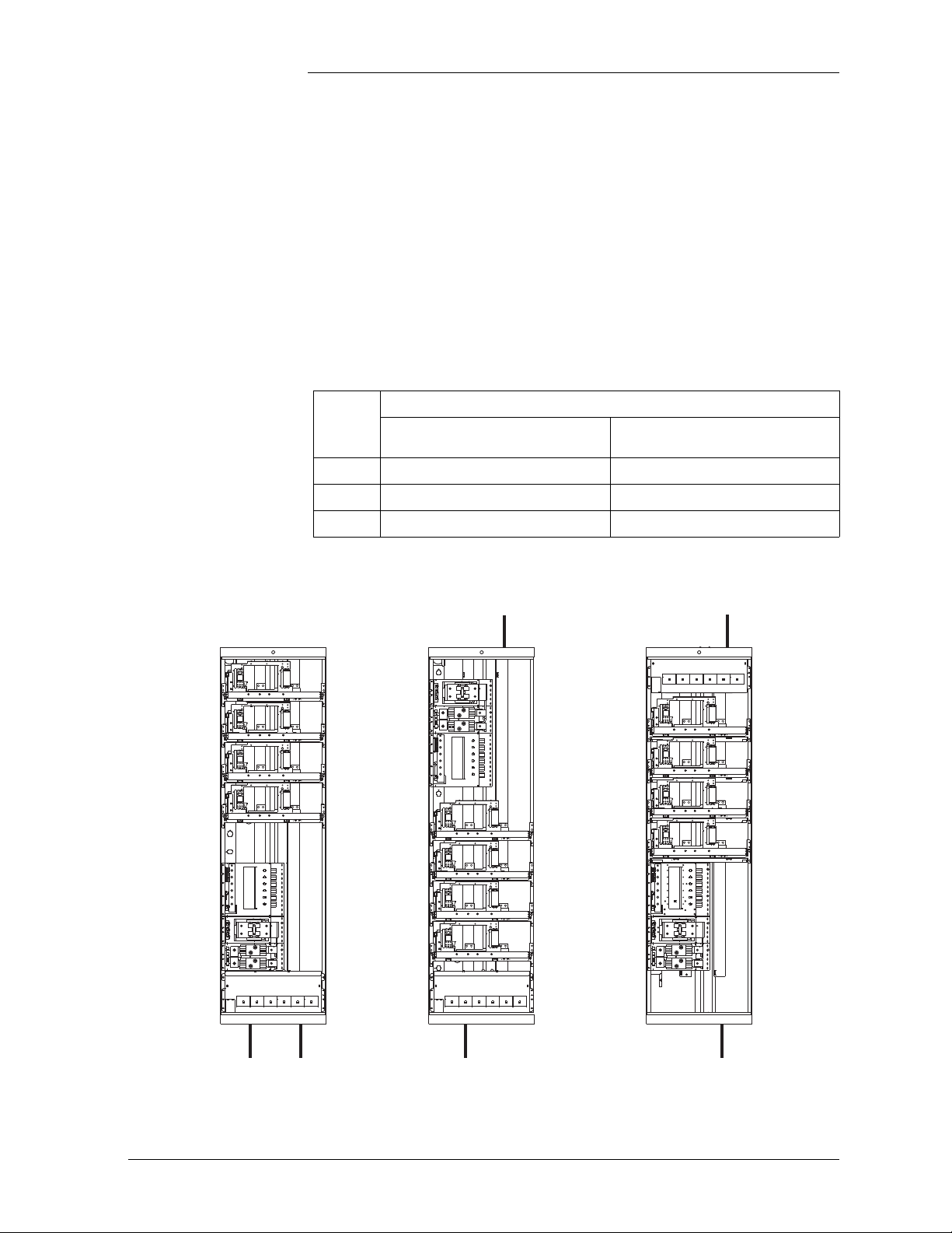
Non-Traditional Any of the battery panels and dc load panels (shown in Sections 6 and
7) may be used in cabinets that have non-traditional cabling orientations.
However, only G20, G22, G24, G26, and G27 ac panels (shown in
Section 5) are available for these cabinets (see Figure 2-6). Suffixes of
the ac panels indicate the cabling arrangements listed below:
AC
Cabling Arrangement
Panel
Suffix
A
B
C
Note: Check
Through bottom of cabinet Through bottom of cabinet
Through bottom of cabinet Through top of cabinet
Through top of cabinet Through bottom of cabinet
H569-434 for availability.
AC Battery and DC Load
Figure 2-6: Non-Traditional Cabling Arrangements
Issue 5 September 2011 System Description 2 - 7

Galaxy Power System 4848/100 with Dual Rectifier Shelf
2 - 8 System Description Issue 5 September 2011


Galaxy Power System 4848/100 with Dual Rectifier Shelf
2 - 10 System Description Issue 5 September 2011
Loading...