


 Loading...

DEH-431
Warnings, Cautions, and Notes as used in this publication
Warnings
WARNING! Warning notices are used in this publication to emphasize that hazardous voltages, currents, or other conditions that could cause personal injury exist in this equipment or may be associated with its use.
Warning notices are also used for situations in which inattention or lack of equipment knowledge could cause either personal injury or damage to equipment.
Cautions
CAUTION: Caution notices are used for situations in which equipment might be damaged if care is not taken.
Notes
NOTE: Notes call attention to information that is especially significant to understanding and operating the equipment.
This document is based on information available at the time of its publication. While efforts have been made to ensure accuracy, the information contained herein does not cover all details or variations in hardware and software, nor does it provide for every possible contingency in connection with installation, operation, and maintenance. Features may be described in here that are not present in all hardware and software systems. GE Consumer & Industrial assumes no obligation of notice to holders of this document with respect to changes subsequently made.
GE Consumer & Industrial makes no representation or warranty, expressed, implied, or statutory, with respect to, and assumes no responsibility for the accuracy, completeness, sufficiency, or usefulness of the information contained herein. No warrantees of merchantability or fitness for purpose shall apply.
Entellisys™, EntelliGuard™, and FlexLogic™ are trademarks of the General Electric Company.
Modbus RTU is a registered trademark of AEG Schneider Automation.
Second revision. Corresponds to Entellisys HMI versions 4.0 and 4.01.
©Copyright 2005, 2007, 2008 General Electric
All Rights Reserved
How to contact us
Please have your Entellisys System Summary # and Sub # ready when calling. This information can be found on the Entellisys HMI on the System Health screen by clicking the Job Info button.
Post Sales Service
GE Switchgear
510 Agency Road
West Burlington, IA 52655
Phone (toll free): 1-888-437-3765
Additional information: www.entellisys.com
Contents
1 System architecture
1.1 Description of operation . . . . . . . . . . . . . . . . . . . . . . . . . . . . . . . . . . . . . . . . . . . . . . . . . . . . . . . . . . . . . . . . . . . . . . . . . . . . . . 13 1.2 Switchgear installations . . . . . . . . . . . . . . . . . . . . . . . . . . . . . . . . . . . . . . . . . . . . . . . . . . . . . . . . . . . . . . . . . . . . . . . . . . . . . . 14 1.3 System components. . . . . . . . . . . . . . . . . . . . . . . . . . . . . . . . . . . . . . . . . . . . . . . . . . . . . . . . . . . . . . . . . . . . . . . . . . . . . . . . . . 15 1.3.1 EntelliGuard circuit breaker . . . . . . . . . . . . . . . . . . . . . . . . . . . . . . . . . . . . . . . . . . . . . . . . . . . . . . . . . . . . . . . . . . . . . . 15 1.3.2 Current transformers . . . . . . . . . . . . . . . . . . . . . . . . . . . . . . . . . . . . . . . . . . . . . . . . . . . . . . . . . . . . . . . . . . . . . . . . . . . . 16 1.3.3 Potential transformers . . . . . . . . . . . . . . . . . . . . . . . . . . . . . . . . . . . . . . . . . . . . . . . . . . . . . . . . . . . . . . . . . . . . . . . . . . . 17 1.3.4 EntelliGuard Messenger. . . . . . . . . . . . . . . . . . . . . . . . . . . . . . . . . . . . . . . . . . . . . . . . . . . . . . . . . . . . . . . . . . . . . . . . . . 18 1.3.4.1 Messenger User Interface. . . . . . . . . . . . . . . . . . . . . . . . . . . . . . . . . . . . . . . . . . . . . . . . . . . . . . . . . . . . . . . . . . . 18 1.3.5 Compartment ID button . . . . . . . . . . . . . . . . . . . . . . . . . . . . . . . . . . . . . . . . . . . . . . . . . . . . . . . . . . . . . . . . . . . . . . . . . 19 1.3.6 Messenger communications network. . . . . . . . . . . . . . . . . . . . . . . . . . . . . . . . . . . . . . . . . . . . . . . . . . . . . . . . . . . . . 20 1.3.7 Messenger switch . . . . . . . . . . . . . . . . . . . . . . . . . . . . . . . . . . . . . . . . . . . . . . . . . . . . . . . . . . . . . . . . . . . . . . . . . . . . . . . 20 1.3.8 CPU. . . . . . . . . . . . . . . . . . . . . . . . . . . . . . . . . . . . . . . . . . . . . . . . . . . . . . . . . . . . . . . . . . . . . . . . . . . . . . . . . . . . . . . . . . . . . 21 1.3.9 Synch clock . . . . . . . . . . . . . . . . . . . . . . . . . . . . . . . . . . . . . . . . . . . . . . . . . . . . . . . . . . . . . . . . . . . . . . . . . . . . . . . . . . . . . 21 1.3.10 Discrete I/O . . . . . . . . . . . . . . . . . . . . . . . . . . . . . . . . . . . . . . . . . . . . . . . . . . . . . . . . . . . . . . . . . . . . . . . . . . . . . . . . . . . . 22 1.3.10.1 Discrete I/O cards . . . . . . . . . . . . . . . . . . . . . . . . . . . . . . . . . . . . . . . . . . . . . . . . . . . . . . . . . . . . . . . . . . . . . . . . . 22 1.3.10.2 Discrete I/O cable . . . . . . . . . . . . . . . . . . . . . . . . . . . . . . . . . . . . . . . . . . . . . . . . . . . . . . . . . . . . . . . . . . . . . . . . . 22 1.3.10.3 Terminal block . . . . . . . . . . . . . . . . . . . . . . . . . . . . . . . . . . . . . . . . . . . . . . . . . . . . . . . . . . . . . . . . . . . . . . . . . . . . 22 1.3.10.4 “OR” boards. . . . . . . . . . . . . . . . . . . . . . . . . . . . . . . . . . . . . . . . . . . . . . . . . . . . . . . . . . . . . . . . . . . . . . . . . . . . . . . 22 1.3.10.5 Relay blocks . . . . . . . . . . . . . . . . . . . . . . . . . . . . . . . . . . . . . . . . . . . . . . . . . . . . . . . . . . . . . . . . . . . . . . . . . . . . . . 22 1.3.10.6 Relays . . . . . . . . . . . . . . . . . . . . . . . . . . . . . . . . . . . . . . . . . . . . . . . . . . . . . . . . . . . . . . . . . . . . . . . . . . . . . . . . . . . . 22 1.3.10.7 Discrete I/O customer interface wiring . . . . . . . . . . . . . . . . . . . . . . . . . . . . . . . . . . . . . . . . . . . . . . . . . . . . . 23 1.3.11 System interface Ethernet communication network. . . . . . . . . . . . . . . . . . . . . . . . . . . . . . . . . . . . . . . . . . . . . . 23 1.3.12 System interface Ethernet switch . . . . . . . . . . . . . . . . . . . . . . . . . . . . . . . . . . . . . . . . . . . . . . . . . . . . . . . . . . . . . . . 23 1.3.13 Touchscreen HMI. . . . . . . . . . . . . . . . . . . . . . . . . . . . . . . . . . . . . . . . . . . . . . . . . . . . . . . . . . . . . . . . . . . . . . . . . . . . . . . 24 1.3.13.1 In-gear HMI . . . . . . . . . . . . . . . . . . . . . . . . . . . . . . . . . . . . . . . . . . . . . . . . . . . . . . . . . . . . . . . . . . . . . . . . . . . . . . . 24 1.3.13.2 Near-gear HMI . . . . . . . . . . . . . . . . . . . . . . . . . . . . . . . . . . . . . . . . . . . . . . . . . . . . . . . . . . . . . . . . . . . . . . . . . . . . 24 1.3.14 Remote HMI . . . . . . . . . . . . . . . . . . . . . . . . . . . . . . . . . . . . . . . . . . . . . . . . . . . . . . . . . . . . . . . . . . . . . . . . . . . . . . . . . . . 25 1.3.15 VPN firewall device . . . . . . . . . . . . . . . . . . . . . . . . . . . . . . . . . . . . . . . . . . . . . . . . . . . . . . . . . . . . . . . . . . . . . . . . . . . . . 25 1.3.16 Control power. . . . . . . . . . . . . . . . . . . . . . . . . . . . . . . . . . . . . . . . . . . . . . . . . . . . . . . . . . . . . . . . . . . . . . . . . . . . . . . . . . 25 1.3.17 UPS. . . . . . . . . . . . . . . . . . . . . . . . . . . . . . . . . . . . . . . . . . . . . . . . . . . . . . . . . . . . . . . . . . . . . . . . . . . . . . . . . . . . . . . . . . . . 25 1.3.18 UPS to HMI connection . . . . . . . . . . . . . . . . . . . . . . . . . . . . . . . . . . . . . . . . . . . . . . . . . . . . . . . . . . . . . . . . . . . . . . . . . 26 1.3.19 RS-232 to RS-485 converter . . . . . . . . . . . . . . . . . . . . . . . . . . . . . . . . . . . . . . . . . . . . . . . . . . . . . . . . . . . . . . . . . . . . 26 1.3.20 Entellisys System Test Kit . . . . . . . . . . . . . . . . . . . . . . . . . . . . . . . . . . . . . . . . . . . . . . . . . . . . . . . . . . . . . . . . . . . . . . . 26 1.3.21 Clamp circuit. . . . . . . . . . . . . . . . . . . . . . . . . . . . . . . . . . . . . . . . . . . . . . . . . . . . . . . . . . . . . . . . . . . . . . . . . . . . . . . . . . . 26
2 Specifications
2.1 Environmental. . . . . . . . . . . . . . . . . . . . . . . . . . . . . . . . . . . . . . . . . . . . . . . . . . . . . . . . . . . . . . . . . . . . . . . . . . . . . . . . . . . . . . . . 27 2.2 Type tests . . . . . . . . . . . . . . . . . . . . . . . . . . . . . . . . . . . . . . . . . . . . . . . . . . . . . . . . . . . . . . . . . . . . . . . . . . . . . . . . . . . . . . . . . . . . 27 2.3 Approvals . . . . . . . . . . . . . . . . . . . . . . . . . . . . . . . . . . . . . . . . . . . . . . . . . . . . . . . . . . . . . . . . . . . . . . . . . . . . . . . . . . . . . . . . . . . . 28
3 HMI Basics
3.1 Entellisys HMI Overview. . . . . . . . . . . . . . . . . . . . . . . . . . . . . . . . . . . . . . . . . . . . . . . . . . . . . . . . . . . . . . . . . . . . . . . . . . . . . . . 29 3.1.1 The Header Pane . . . . . . . . . . . . . . . . . . . . . . . . . . . . . . . . . . . . . . . . . . . . . . . . . . . . . . . . . . . . . . . . . . . . . . . . . . . . . . . . 30 3.1.2 The status bar. . . . . . . . . . . . . . . . . . . . . . . . . . . . . . . . . . . . . . . . . . . . . . . . . . . . . . . . . . . . . . . . . . . . . . . . . . . . . . . . . . . 31 3.1.3 Main Menu . . . . . . . . . . . . . . . . . . . . . . . . . . . . . . . . . . . . . . . . . . . . . . . . . . . . . . . . . . . . . . . . . . . . . . . . . . . . . . . . . . . . . . 31
Contents 5
3.1.4 Breaker Status Screen . . . . . . . . . . . . . . . . . . . . . . . . . . . . . . . . . . . . . . . . . . . . . . . . . . . . . . . . . . . . . . . . . . . . . . . . . . . 32 3.2 Job Documentation . . . . . . . . . . . . . . . . . . . . . . . . . . . . . . . . . . . . . . . . . . . . . . . . . . . . . . . . . . . . . . . . . . . . . . . . . . . . . . . . . . 33 3.3 Controlling circuit breakers . . . . . . . . . . . . . . . . . . . . . . . . . . . . . . . . . . . . . . . . . . . . . . . . . . . . . . . . . . . . . . . . . . . . . . . . . . . 34 3.3.1 Block other HMIs . . . . . . . . . . . . . . . . . . . . . . . . . . . . . . . . . . . . . . . . . . . . . . . . . . . . . . . . . . . . . . . . . . . . . . . . . . . . . . . . 35 3.3.2 Open circuit breaker (electrically operated circuit breakers only) . . . . . . . . . . . . . . . . . . . . . . . . . . . . . . . . . . . 35 3.3.3 Close circuit breaker (electrically operated circuit breakers only) . . . . . . . . . . . . . . . . . . . . . . . . . . . . . . . . . . . 35 3.3.4 Trip circuit breaker . . . . . . . . . . . . . . . . . . . . . . . . . . . . . . . . . . . . . . . . . . . . . . . . . . . . . . . . . . . . . . . . . . . . . . . . . . . . . . 36 3.3.5 Locator LED . . . . . . . . . . . . . . . . . . . . . . . . . . . . . . . . . . . . . . . . . . . . . . . . . . . . . . . . . . . . . . . . . . . . . . . . . . . . . . . . . . . . . 36 3.3.6 Troubleshooting . . . . . . . . . . . . . . . . . . . . . . . . . . . . . . . . . . . . . . . . . . . . . . . . . . . . . . . . . . . . . . . . . . . . . . . . . . . . . . . . . 36
4 Metering
4.1 Basic metering . . . . . . . . . . . . . . . . . . . . . . . . . . . . . . . . . . . . . . . . . . . . . . . . . . . . . . . . . . . . . . . . . . . . . . . . . . . . . . . . . . . . . . . 37 4.2 Expanded metering. . . . . . . . . . . . . . . . . . . . . . . . . . . . . . . . . . . . . . . . . . . . . . . . . . . . . . . . . . . . . . . . . . . . . . . . . . . . . . . . . . . 37 4.3 Demand metering . . . . . . . . . . . . . . . . . . . . . . . . . . . . . . . . . . . . . . . . . . . . . . . . . . . . . . . . . . . . . . . . . . . . . . . . . . . . . . . . . . . . 38 4.4 Advanced metering. . . . . . . . . . . . . . . . . . . . . . . . . . . . . . . . . . . . . . . . . . . . . . . . . . . . . . . . . . . . . . . . . . . . . . . . . . . . . . . . . . . 39 4.5 Metering accuracy . . . . . . . . . . . . . . . . . . . . . . . . . . . . . . . . . . . . . . . . . . . . . . . . . . . . . . . . . . . . . . . . . . . . . . . . . . . . . . . . . . . 40 4.6 Setup . . . . . . . . . . . . . . . . . . . . . . . . . . . . . . . . . . . . . . . . . . . . . . . . . . . . . . . . . . . . . . . . . . . . . . . . . . . . . . . . . . . . . . . . . . . . . . . . 41
4.6.1 Basic configuration . . . . . . . . . . . . . . . . . . . . . . . . . . . . . . . . . . . . . . . . . . . . . . . . . . . . . . . . . . . . . . . . . . . . . . . . . . . . . . 41 4.6.2 Options . . . . . . . . . . . . . . . . . . . . . . . . . . . . . . . . . . . . . . . . . . . . . . . . . . . . . . . . . . . . . . . . . . . . . . . . . . . . . . . . . . . . . . . . . 43 4.6.3 Programmable parameters . . . . . . . . . . . . . . . . . . . . . . . . . . . . . . . . . . . . . . . . . . . . . . . . . . . . . . . . . . . . . . . . . . . . . . 43 4.6.4 Meter distribution . . . . . . . . . . . . . . . . . . . . . . . . . . . . . . . . . . . . . . . . . . . . . . . . . . . . . . . . . . . . . . . . . . . . . . . . . . . . . . . 43 4.7 Usage. . . . . . . . . . . . . . . . . . . . . . . . . . . . . . . . . . . . . . . . . . . . . . . . . . . . . . . . . . . . . . . . . . . . . . . . . . . . . . . . . . . . . . . . . . . . . . . . 46 4.7.1 Viewing basic metering data . . . . . . . . . . . . . . . . . . . . . . . . . . . . . . . . . . . . . . . . . . . . . . . . . . . . . . . . . . . . . . . . . . . . . 46 4.7.2 Viewing demand metering data . . . . . . . . . . . . . . . . . . . . . . . . . . . . . . . . . . . . . . . . . . . . . . . . . . . . . . . . . . . . . . . . . . 47 4.7.3 Viewing detailed metering data . . . . . . . . . . . . . . . . . . . . . . . . . . . . . . . . . . . . . . . . . . . . . . . . . . . . . . . . . . . . . . . . . . 50 4.7.4 Viewing harmonics metering data. . . . . . . . . . . . . . . . . . . . . . . . . . . . . . . . . . . . . . . . . . . . . . . . . . . . . . . . . . . . . . . . 51 4.7.5 Viewing frequency harmonics. . . . . . . . . . . . . . . . . . . . . . . . . . . . . . . . . . . . . . . . . . . . . . . . . . . . . . . . . . . . . . . . . . . . 52 4.8 Troubleshooting . . . . . . . . . . . . . . . . . . . . . . . . . . . . . . . . . . . . . . . . . . . . . . . . . . . . . . . . . . . . . . . . . . . . . . . . . . . . . . . . . . . . . . 53
5 Single point functions
5.1 Overcurrent protection . . . . . . . . . . . . . . . . . . . . . . . . . . . . . . . . . . . . . . . . . . . . . . . . . . . . . . . . . . . . . . . . . . . . . . . . . . . . . . . 55 5.1.1 Long Time Overcurrent protection. . . . . . . . . . . . . . . . . . . . . . . . . . . . . . . . . . . . . . . . . . . . . . . . . . . . . . . . . . . . . . . . 55 5.1.1.1 Accuracy. . . . . . . . . . . . . . . . . . . . . . . . . . . . . . . . . . . . . . . . . . . . . . . . . . . . . . . . . . . . . . . . . . . . . . . . . . . . . . . . . . . 56 5.1.1.2 Setup . . . . . . . . . . . . . . . . . . . . . . . . . . . . . . . . . . . . . . . . . . . . . . . . . . . . . . . . . . . . . . . . . . . . . . . . . . . . . . . . . . . . . . 56 5.1.1.3 Usage . . . . . . . . . . . . . . . . . . . . . . . . . . . . . . . . . . . . . . . . . . . . . . . . . . . . . . . . . . . . . . . . . . . . . . . . . . . . . . . . . . . . . 57 5.1.2 IOC/Short Time Overcurrent protection . . . . . . . . . . . . . . . . . . . . . . . . . . . . . . . . . . . . . . . . . . . . . . . . . . . . . . . . . . . 58 5.1.2.1 Short Time Overcurrent protection curves . . . . . . . . . . . . . . . . . . . . . . . . . . . . . . . . . . . . . . . . . . . . . . . . . . . 58 5.1.2.2 Accuracy. . . . . . . . . . . . . . . . . . . . . . . . . . . . . . . . . . . . . . . . . . . . . . . . . . . . . . . . . . . . . . . . . . . . . . . . . . . . . . . . . . . 59 5.1.2.3 Setup . . . . . . . . . . . . . . . . . . . . . . . . . . . . . . . . . . . . . . . . . . . . . . . . . . . . . . . . . . . . . . . . . . . . . . . . . . . . . . . . . . . . . . 59 5.1.2.4 Usage . . . . . . . . . . . . . . . . . . . . . . . . . . . . . . . . . . . . . . . . . . . . . . . . . . . . . . . . . . . . . . . . . . . . . . . . . . . . . . . . . . . . . 62 5.1.3 Ground Fault protection . . . . . . . . . . . . . . . . . . . . . . . . . . . . . . . . . . . . . . . . . . . . . . . . . . . . . . . . . . . . . . . . . . . . . . . . . 62 5.1.3.1 Ground Fault protection curves . . . . . . . . . . . . . . . . . . . . . . . . . . . . . . . . . . . . . . . . . . . . . . . . . . . . . . . . . . . . . 62 5.1.3.2 Accuracy. . . . . . . . . . . . . . . . . . . . . . . . . . . . . . . . . . . . . . . . . . . . . . . . . . . . . . . . . . . . . . . . . . . . . . . . . . . . . . . . . . . 63 5.1.3.3 Setup . . . . . . . . . . . . . . . . . . . . . . . . . . . . . . . . . . . . . . . . . . . . . . . . . . . . . . . . . . . . . . . . . . . . . . . . . . . . . . . . . . . . . . 63 5.1.3.4 Usage . . . . . . . . . . . . . . . . . . . . . . . . . . . . . . . . . . . . . . . . . . . . . . . . . . . . . . . . . . . . . . . . . . . . . . . . . . . . . . . . . . . . . 65
5.2 Single Point Relay protection . . . . . . . . . . . . . . . . . . . . . . . . . . . . . . . . . . . . . . . . . . . . . . . . . . . . . . . . . . . . . . . . . . . . . . . . . . 66 5.2.0.1 Enabling Single Point Relay packages . . . . . . . . . . . . . . . . . . . . . . . . . . . . . . . . . . . . . . . . . . . . . . . . . . . . . . . 67 5.2.1 Undervoltage Relay. . . . . . . . . . . . . . . . . . . . . . . . . . . . . . . . . . . . . . . . . . . . . . . . . . . . . . . . . . . . . . . . . . . . . . . . . . . . . . 67 5.2.1.1 Setup . . . . . . . . . . . . . . . . . . . . . . . . . . . . . . . . . . . . . . . . . . . . . . . . . . . . . . . . . . . . . . . . . . . . . . . . . . . . . . . . . . . . . . 68 5.2.1.2 Trip settings . . . . . . . . . . . . . . . . . . . . . . . . . . . . . . . . . . . . . . . . . . . . . . . . . . . . . . . . . . . . . . . . . . . . . . . . . . . . . . . . 68 5.2.1.3 Alarm settings. . . . . . . . . . . . . . . . . . . . . . . . . . . . . . . . . . . . . . . . . . . . . . . . . . . . . . . . . . . . . . . . . . . . . . . . . . . . . . 69
6 Contents
5.2.1.4 Usage . . . . . . . . . . . . . . . . . . . . . . . . . . . . . . . . . . . . . . . . . . . . . . . . . . . . . . . . . . . . . . . . . . . . . . . . . . . . . . . . . . . . . 70 5.2.2 Overvoltage Relay . . . . . . . . . . . . . . . . . . . . . . . . . . . . . . . . . . . . . . . . . . . . . . . . . . . . . . . . . . . . . . . . . . . . . . . . . . . . . . . 71 5.2.2.1 Accuracy. . . . . . . . . . . . . . . . . . . . . . . . . . . . . . . . . . . . . . . . . . . . . . . . . . . . . . . . . . . . . . . . . . . . . . . . . . . . . . . . . . . 71 5.2.2.2 Setup . . . . . . . . . . . . . . . . . . . . . . . . . . . . . . . . . . . . . . . . . . . . . . . . . . . . . . . . . . . . . . . . . . . . . . . . . . . . . . . . . . . . . . 71 5.2.2.3 Trip settings . . . . . . . . . . . . . . . . . . . . . . . . . . . . . . . . . . . . . . . . . . . . . . . . . . . . . . . . . . . . . . . . . . . . . . . . . . . . . . . . 71 5.2.2.4 Alarm settings. . . . . . . . . . . . . . . . . . . . . . . . . . . . . . . . . . . . . . . . . . . . . . . . . . . . . . . . . . . . . . . . . . . . . . . . . . . . . . 72 5.2.2.5 Usage . . . . . . . . . . . . . . . . . . . . . . . . . . . . . . . . . . . . . . . . . . . . . . . . . . . . . . . . . . . . . . . . . . . . . . . . . . . . . . . . . . . . . 73 5.2.3 Over Frequency Relay . . . . . . . . . . . . . . . . . . . . . . . . . . . . . . . . . . . . . . . . . . . . . . . . . . . . . . . . . . . . . . . . . . . . . . . . . . . 73 5.2.3.1 Accuracy. . . . . . . . . . . . . . . . . . . . . . . . . . . . . . . . . . . . . . . . . . . . . . . . . . . . . . . . . . . . . . . . . . . . . . . . . . . . . . . . . . . 73 5.2.3.2 Setup . . . . . . . . . . . . . . . . . . . . . . . . . . . . . . . . . . . . . . . . . . . . . . . . . . . . . . . . . . . . . . . . . . . . . . . . . . . . . . . . . . . . . . 74 5.2.3.3 Trip settings . . . . . . . . . . . . . . . . . . . . . . . . . . . . . . . . . . . . . . . . . . . . . . . . . . . . . . . . . . . . . . . . . . . . . . . . . . . . . . . . 74 5.2.3.4 Alarm settings. . . . . . . . . . . . . . . . . . . . . . . . . . . . . . . . . . . . . . . . . . . . . . . . . . . . . . . . . . . . . . . . . . . . . . . . . . . . . . 74 5.2.3.5 Usage . . . . . . . . . . . . . . . . . . . . . . . . . . . . . . . . . . . . . . . . . . . . . . . . . . . . . . . . . . . . . . . . . . . . . . . . . . . . . . . . . . . . . 75 5.2.4 Under Frequency Relay . . . . . . . . . . . . . . . . . . . . . . . . . . . . . . . . . . . . . . . . . . . . . . . . . . . . . . . . . . . . . . . . . . . . . . . . . . 76 5.2.4.1 Accuracy. . . . . . . . . . . . . . . . . . . . . . . . . . . . . . . . . . . . . . . . . . . . . . . . . . . . . . . . . . . . . . . . . . . . . . . . . . . . . . . . . . . 76 5.2.4.2 Setup . . . . . . . . . . . . . . . . . . . . . . . . . . . . . . . . . . . . . . . . . . . . . . . . . . . . . . . . . . . . . . . . . . . . . . . . . . . . . . . . . . . . . . 77 5.2.4.3 Trip settings . . . . . . . . . . . . . . . . . . . . . . . . . . . . . . . . . . . . . . . . . . . . . . . . . . . . . . . . . . . . . . . . . . . . . . . . . . . . . . . . 77 5.2.4.4 Alarm settings. . . . . . . . . . . . . . . . . . . . . . . . . . . . . . . . . . . . . . . . . . . . . . . . . . . . . . . . . . . . . . . . . . . . . . . . . . . . . . 77 5.2.4.5 Usage . . . . . . . . . . . . . . . . . . . . . . . . . . . . . . . . . . . . . . . . . . . . . . . . . . . . . . . . . . . . . . . . . . . . . . . . . . . . . . . . . . . . . 78 5.2.5 Phase Loss Relay protection . . . . . . . . . . . . . . . . . . . . . . . . . . . . . . . . . . . . . . . . . . . . . . . . . . . . . . . . . . . . . . . . . . . . . 79 5.2.5.1 Accuracy. . . . . . . . . . . . . . . . . . . . . . . . . . . . . . . . . . . . . . . . . . . . . . . . . . . . . . . . . . . . . . . . . . . . . . . . . . . . . . . . . . . 79 5.2.5.2 Setup . . . . . . . . . . . . . . . . . . . . . . . . . . . . . . . . . . . . . . . . . . . . . . . . . . . . . . . . . . . . . . . . . . . . . . . . . . . . . . . . . . . . . . 80 5.2.5.3 Trip settings . . . . . . . . . . . . . . . . . . . . . . . . . . . . . . . . . . . . . . . . . . . . . . . . . . . . . . . . . . . . . . . . . . . . . . . . . . . . . . . . 80 5.2.5.4 Alarm settings. . . . . . . . . . . . . . . . . . . . . . . . . . . . . . . . . . . . . . . . . . . . . . . . . . . . . . . . . . . . . . . . . . . . . . . . . . . . . . 80 5.2.5.5 Usage . . . . . . . . . . . . . . . . . . . . . . . . . . . . . . . . . . . . . . . . . . . . . . . . . . . . . . . . . . . . . . . . . . . . . . . . . . . . . . . . . . . . . 81 5.2.6 Reverse Power Relay . . . . . . . . . . . . . . . . . . . . . . . . . . . . . . . . . . . . . . . . . . . . . . . . . . . . . . . . . . . . . . . . . . . . . . . . . . . . 82 5.2.6.1 Accuracy. . . . . . . . . . . . . . . . . . . . . . . . . . . . . . . . . . . . . . . . . . . . . . . . . . . . . . . . . . . . . . . . . . . . . . . . . . . . . . . . . . . 82 5.2.6.2 Setup . . . . . . . . . . . . . . . . . . . . . . . . . . . . . . . . . . . . . . . . . . . . . . . . . . . . . . . . . . . . . . . . . . . . . . . . . . . . . . . . . . . . . . 82 5.2.6.3 Trip settings . . . . . . . . . . . . . . . . . . . . . . . . . . . . . . . . . . . . . . . . . . . . . . . . . . . . . . . . . . . . . . . . . . . . . . . . . . . . . . . . 82 5.2.6.4 Alarm settings. . . . . . . . . . . . . . . . . . . . . . . . . . . . . . . . . . . . . . . . . . . . . . . . . . . . . . . . . . . . . . . . . . . . . . . . . . . . . . 83 5.2.6.5 Usage . . . . . . . . . . . . . . . . . . . . . . . . . . . . . . . . . . . . . . . . . . . . . . . . . . . . . . . . . . . . . . . . . . . . . . . . . . . . . . . . . . . . . 84 5.2.7 High Current Relay . . . . . . . . . . . . . . . . . . . . . . . . . . . . . . . . . . . . . . . . . . . . . . . . . . . . . . . . . . . . . . . . . . . . . . . . . . . . . . 84 5.2.7.1 Accuracy. . . . . . . . . . . . . . . . . . . . . . . . . . . . . . . . . . . . . . . . . . . . . . . . . . . . . . . . . . . . . . . . . . . . . . . . . . . . . . . . . . . 84 5.2.7.2 Setup . . . . . . . . . . . . . . . . . . . . . . . . . . . . . . . . . . . . . . . . . . . . . . . . . . . . . . . . . . . . . . . . . . . . . . . . . . . . . . . . . . . . . . 84 5.2.7.3 Alarm settings. . . . . . . . . . . . . . . . . . . . . . . . . . . . . . . . . . . . . . . . . . . . . . . . . . . . . . . . . . . . . . . . . . . . . . . . . . . . . . 85 5.2.7.4 Usage . . . . . . . . . . . . . . . . . . . . . . . . . . . . . . . . . . . . . . . . . . . . . . . . . . . . . . . . . . . . . . . . . . . . . . . . . . . . . . . . . . . . . 85 5.2.7.5 Event logging . . . . . . . . . . . . . . . . . . . . . . . . . . . . . . . . . . . . . . . . . . . . . . . . . . . . . . . . . . . . . . . . . . . . . . . . . . . . . . 85 5.2.8 High Resistance Ground Fault Detection Relay . . . . . . . . . . . . . . . . . . . . . . . . . . . . . . . . . . . . . . . . . . . . . . . . . . . . 86 5.2.8.1 Accuracy. . . . . . . . . . . . . . . . . . . . . . . . . . . . . . . . . . . . . . . . . . . . . . . . . . . . . . . . . . . . . . . . . . . . . . . . . . . . . . . . . . . 86 5.2.8.2 Setup . . . . . . . . . . . . . . . . . . . . . . . . . . . . . . . . . . . . . . . . . . . . . . . . . . . . . . . . . . . . . . . . . . . . . . . . . . . . . . . . . . . . . . 86 5.2.8.3 Alarm settings. . . . . . . . . . . . . . . . . . . . . . . . . . . . . . . . . . . . . . . . . . . . . . . . . . . . . . . . . . . . . . . . . . . . . . . . . . . . . . 86 5.2.8.4 Usage . . . . . . . . . . . . . . . . . . . . . . . . . . . . . . . . . . . . . . . . . . . . . . . . . . . . . . . . . . . . . . . . . . . . . . . . . . . . . . . . . . . . . 87 5.2.8.5 Event logging . . . . . . . . . . . . . . . . . . . . . . . . . . . . . . . . . . . . . . . . . . . . . . . . . . . . . . . . . . . . . . . . . . . . . . . . . . . . . . 87 5.2.9 High Resistance Ground Fault Location Relay . . . . . . . . . . . . . . . . . . . . . . . . . . . . . . . . . . . . . . . . . . . . . . . . . . . . . 88 5.2.9.1 Hardware Requirements. . . . . . . . . . . . . . . . . . . . . . . . . . . . . . . . . . . . . . . . . . . . . . . . . . . . . . . . . . . . . . . . . . . . 89 5.2.9.2 Accuracy. . . . . . . . . . . . . . . . . . . . . . . . . . . . . . . . . . . . . . . . . . . . . . . . . . . . . . . . . . . . . . . . . . . . . . . . . . . . . . . . . . . 90 5.2.9.3 Setup . . . . . . . . . . . . . . . . . . . . . . . . . . . . . . . . . . . . . . . . . . . . . . . . . . . . . . . . . . . . . . . . . . . . . . . . . . . . . . . . . . . . . . 91 5.2.9.4 Tripping . . . . . . . . . . . . . . . . . . . . . . . . . . . . . . . . . . . . . . . . . . . . . . . . . . . . . . . . . . . . . . . . . . . . . . . . . . . . . . . . . . . . 92 5.2.9.5 Manual Mode . . . . . . . . . . . . . . . . . . . . . . . . . . . . . . . . . . . . . . . . . . . . . . . . . . . . . . . . . . . . . . . . . . . . . . . . . . . . . . 94 5.2.9.6 Events and Alarms. . . . . . . . . . . . . . . . . . . . . . . . . . . . . . . . . . . . . . . . . . . . . . . . . . . . . . . . . . . . . . . . . . . . . . . . . . 94
Contents 7
5.3 Synch Check relay . . . . . . . . . . . . . . . . . . . . . . . . . . . . . . . . . . . . . . . . . . . . . . . . . . . . . . . . . . . . . . . . . . . . . . . . . . . . . . . . . . . . 95 5.3.1 Synch check status . . . . . . . . . . . . . . . . . . . . . . . . . . . . . . . . . . . . . . . . . . . . . . . . . . . . . . . . . . . . . . . . . . . . . . . . . . . . . . 95 5.3.2 Setup . . . . . . . . . . . . . . . . . . . . . . . . . . . . . . . . . . . . . . . . . . . . . . . . . . . . . . . . . . . . . . . . . . . . . . . . . . . . . . . . . . . . . . . . . . . 96 5.3.2.1 Source voltages . . . . . . . . . . . . . . . . . . . . . . . . . . . . . . . . . . . . . . . . . . . . . . . . . . . . . . . . . . . . . . . . . . . . . . . . . . . . 96 5.3.2.2 Maximum differentials . . . . . . . . . . . . . . . . . . . . . . . . . . . . . . . . . . . . . . . . . . . . . . . . . . . . . . . . . . . . . . . . . . . . . . 96 5.3.2.3 Source 1 . . . . . . . . . . . . . . . . . . . . . . . . . . . . . . . . . . . . . . . . . . . . . . . . . . . . . . . . . . . . . . . . . . . . . . . . . . . . . . . . . . . 96 5.3.2.4 Source 2 . . . . . . . . . . . . . . . . . . . . . . . . . . . . . . . . . . . . . . . . . . . . . . . . . . . . . . . . . . . . . . . . . . . . . . . . . . . . . . . . . . . 97 5.3.2.5 Configuration . . . . . . . . . . . . . . . . . . . . . . . . . . . . . . . . . . . . . . . . . . . . . . . . . . . . . . . . . . . . . . . . . . . . . . . . . . . . . . 97 5.3.3 Usage. . . . . . . . . . . . . . . . . . . . . . . . . . . . . . . . . . . . . . . . . . . . . . . . . . . . . . . . . . . . . . . . . . . . . . . . . . . . . . . . . . . . . . . . . . . 98 5.3.3.1 Event logging . . . . . . . . . . . . . . . . . . . . . . . . . . . . . . . . . . . . . . . . . . . . . . . . . . . . . . . . . . . . . . . . . . . . . . . . . . . . . . 99
6 Zones, buses, and topologies
6.0.1 Overview. . . . . . . . . . . . . . . . . . . . . . . . . . . . . . . . . . . . . . . . . . . . . . . . . . . . . . . . . . . . . . . . . . . . . . . . . . . . . . . . . . . . . . 101 6.0.1.1 Zones and buses . . . . . . . . . . . . . . . . . . . . . . . . . . . . . . . . . . . . . . . . . . . . . . . . . . . . . . . . . . . . . . . . . . . . . . . . . 101 6.0.1.2 Topologies . . . . . . . . . . . . . . . . . . . . . . . . . . . . . . . . . . . . . . . . . . . . . . . . . . . . . . . . . . . . . . . . . . . . . . . . . . . . . . . 102 6.0.2 Setup . . . . . . . . . . . . . . . . . . . . . . . . . . . . . . . . . . . . . . . . . . . . . . . . . . . . . . . . . . . . . . . . . . . . . . . . . . . . . . . . . . . . . . . . . 102 6.0.2.1 Zones . . . . . . . . . . . . . . . . . . . . . . . . . . . . . . . . . . . . . . . . . . . . . . . . . . . . . . . . . . . . . . . . . . . . . . . . . . . . . . . . . . . . 102 6.0.2.2 Buses, topologies and the Association Matrix . . . . . . . . . . . . . . . . . . . . . . . . . . . . . . . . . . . . . . . . . . . . . . 103 6.0.3 Usage. . . . . . . . . . . . . . . . . . . . . . . . . . . . . . . . . . . . . . . . . . . . . . . . . . . . . . . . . . . . . . . . . . . . . . . . . . . . . . . . . . . . . . . . . 104
7 Multipoint functions
7.1 Bus Differential Relay . . . . . . . . . . . . . . . . . . . . . . . . . . . . . . . . . . . . . . . . . . . . . . . . . . . . . . . . . . . . . . . . . . . . . . . . . . . . . . . 105 7.1.1 Setup . . . . . . . . . . . . . . . . . . . . . . . . . . . . . . . . . . . . . . . . . . . . . . . . . . . . . . . . . . . . . . . . . . . . . . . . . . . . . . . . . . . . . . . . . 105 7.1.1.1 Configuring Bus Differential zones. . . . . . . . . . . . . . . . . . . . . . . . . . . . . . . . . . . . . . . . . . . . . . . . . . . . . . . . . 105 7.1.1.2 User settings . . . . . . . . . . . . . . . . . . . . . . . . . . . . . . . . . . . . . . . . . . . . . . . . . . . . . . . . . . . . . . . . . . . . . . . . . . . . . 105 7.1.1.3 Setting Bus Differential pickups/delays . . . . . . . . . . . . . . . . . . . . . . . . . . . . . . . . . . . . . . . . . . . . . . . . . . . . 106 7.1.1.4 Setting up Bus Differential alarms . . . . . . . . . . . . . . . . . . . . . . . . . . . . . . . . . . . . . . . . . . . . . . . . . . . . . . . . . 107 7.1.2 Troubleshooting . . . . . . . . . . . . . . . . . . . . . . . . . . . . . . . . . . . . . . . . . . . . . . . . . . . . . . . . . . . . . . . . . . . . . . . . . . . . . . . 108 7.1.3 Events generated by the Bus Differential Relay. . . . . . . . . . . . . . . . . . . . . . . . . . . . . . . . . . . . . . . . . . . . . . . . . . 108 7.1.4 Alarms generated by the Bus Differential Relay . . . . . . . . . . . . . . . . . . . . . . . . . . . . . . . . . . . . . . . . . . . . . . . . . 108
7.2 Multi-Source Ground-Fault Relay . . . . . . . . . . . . . . . . . . . . . . . . . . . . . . . . . . . . . . . . . . . . . . . . . . . . . . . . . . . . . . . . . . . . 109 7.2.0.1 Interoperation with Zone Selective Interlock function. . . . . . . . . . . . . . . . . . . . . . . . . . . . . . . . . . . . . . . 109 7.2.1 Setup . . . . . . . . . . . . . . . . . . . . . . . . . . . . . . . . . . . . . . . . . . . . . . . . . . . . . . . . . . . . . . . . . . . . . . . . . . . . . . . . . . . . . . . . . 110 7.2.1.1 User settings . . . . . . . . . . . . . . . . . . . . . . . . . . . . . . . . . . . . . . . . . . . . . . . . . . . . . . . . . . . . . . . . . . . . . . . . . . . . . 110 7.2.1.2 Setting Multi-Source Ground-Fault pickup/delay . . . . . . . . . . . . . . . . . . . . . . . . . . . . . . . . . . . . . . . . . . . 111 7.2.1.3 Setup of Multi-Source Ground-Fault alarms. . . . . . . . . . . . . . . . . . . . . . . . . . . . . . . . . . . . . . . . . . . . . . . . 113 7.2.2 Troubleshooting . . . . . . . . . . . . . . . . . . . . . . . . . . . . . . . . . . . . . . . . . . . . . . . . . . . . . . . . . . . . . . . . . . . . . . . . . . . . . . . 114 7.2.3 Events generated by Multi-Source Ground-Fault Relay . . . . . . . . . . . . . . . . . . . . . . . . . . . . . . . . . . . . . . . . . . 114 7.2.4 Alarms generated by Multi-Source Ground-Fault Relay . . . . . . . . . . . . . . . . . . . . . . . . . . . . . . . . . . . . . . . . . . 114
7.3 PT Throw-Over . . . . . . . . . . . . . . . . . . . . . . . . . . . . . . . . . . . . . . . . . . . . . . . . . . . . . . . . . . . . . . . . . . . . . . . . . . . . . . . . . . . . . 115 7.3.1 Setup . . . . . . . . . . . . . . . . . . . . . . . . . . . . . . . . . . . . . . . . . . . . . . . . . . . . . . . . . . . . . . . . . . . . . . . . . . . . . . . . . . . . . . . . . 116 7.3.2 Usage. . . . . . . . . . . . . . . . . . . . . . . . . . . . . . . . . . . . . . . . . . . . . . . . . . . . . . . . . . . . . . . . . . . . . . . . . . . . . . . . . . . . . . . . . 118 7.4 Zone Selective Interlock. . . . . . . . . . . . . . . . . . . . . . . . . . . . . . . . . . . . . . . . . . . . . . . . . . . . . . . . . . . . . . . . . . . . . . . . . . . . . 119 7.4.1 Zones . . . . . . . . . . . . . . . . . . . . . . . . . . . . . . . . . . . . . . . . . . . . . . . . . . . . . . . . . . . . . . . . . . . . . . . . . . . . . . . . . . . . . . . . . 119 7.4.2 ZSI zones. . . . . . . . . . . . . . . . . . . . . . . . . . . . . . . . . . . . . . . . . . . . . . . . . . . . . . . . . . . . . . . . . . . . . . . . . . . . . . . . . . . . . . 119 7.4.3 Protection types . . . . . . . . . . . . . . . . . . . . . . . . . . . . . . . . . . . . . . . . . . . . . . . . . . . . . . . . . . . . . . . . . . . . . . . . . . . . . . . 119 7.4.4 Topologies . . . . . . . . . . . . . . . . . . . . . . . . . . . . . . . . . . . . . . . . . . . . . . . . . . . . . . . . . . . . . . . . . . . . . . . . . . . . . . . . . . . . 120 7.4.5 Tiers . . . . . . . . . . . . . . . . . . . . . . . . . . . . . . . . . . . . . . . . . . . . . . . . . . . . . . . . . . . . . . . . . . . . . . . . . . . . . . . . . . . . . . . . . . 120 7.4.6 Algorithm . . . . . . . . . . . . . . . . . . . . . . . . . . . . . . . . . . . . . . . . . . . . . . . . . . . . . . . . . . . . . . . . . . . . . . . . . . . . . . . . . . . . . 120 7.4.7 Setup . . . . . . . . . . . . . . . . . . . . . . . . . . . . . . . . . . . . . . . . . . . . . . . . . . . . . . . . . . . . . . . . . . . . . . . . . . . . . . . . . . . . . . . . . 121 7.4.7.1 Configuring ZSI parameters . . . . . . . . . . . . . . . . . . . . . . . . . . . . . . . . . . . . . . . . . . . . . . . . . . . . . . . . . . . . . . . 121
8 Contents
7.4.7.2 Operation . . . . . . . . . . . . . . . . . . . . . . . . . . . . . . . . . . . . . . . . . . . . . . . . . . . . . . . . . . . . . . . . . . . . . . . . . . . . . . . . 123 7.4.7.3 Events . . . . . . . . . . . . . . . . . . . . . . . . . . . . . . . . . . . . . . . . . . . . . . . . . . . . . . . . . . . . . . . . . . . . . . . . . . . . . . . . . . . 124 7.4.7.4 Configuration events . . . . . . . . . . . . . . . . . . . . . . . . . . . . . . . . . . . . . . . . . . . . . . . . . . . . . . . . . . . . . . . . . . . . . 124 7.4.7.5 Confirmation events . . . . . . . . . . . . . . . . . . . . . . . . . . . . . . . . . . . . . . . . . . . . . . . . . . . . . . . . . . . . . . . . . . . . . . 124 7.4.7.6 Operation events . . . . . . . . . . . . . . . . . . . . . . . . . . . . . . . . . . . . . . . . . . . . . . . . . . . . . . . . . . . . . . . . . . . . . . . . . 125
7.4.8 Troubleshooting . . . . . . . . . . . . . . . . . . . . . . . . . . . . . . . . . . . . . . . . . . . . . . . . . . . . . . . . . . . . . . . . . . . . . . . . . . . . . . . 125 7.5 Ground Fault Tripping priority . . . . . . . . . . . . . . . . . . . . . . . . . . . . . . . . . . . . . . . . . . . . . . . . . . . . . . . . . . . . . . . . . . . . . . . 126 7.5.1 Setup . . . . . . . . . . . . . . . . . . . . . . . . . . . . . . . . . . . . . . . . . . . . . . . . . . . . . . . . . . . . . . . . . . . . . . . . . . . . . . . . . . . . . . . . . 127 7.5.2 Usage. . . . . . . . . . . . . . . . . . . . . . . . . . . . . . . . . . . . . . . . . . . . . . . . . . . . . . . . . . . . . . . . . . . . . . . . . . . . . . . . . . . . . . . . . 127
8 Reduced Energy Let-Thru Mode
8.1 Operation . . . . . . . . . . . . . . . . . . . . . . . . . . . . . . . . . . . . . . . . . . . . . . . . . . . . . . . . . . . . . . . . . . . . . . . . . . . . . . . . . . . . . . . . . . 130 8.2 FlexLogic™ Configuration . . . . . . . . . . . . . . . . . . . . . . . . . . . . . . . . . . . . . . . . . . . . . . . . . . . . . . . . . . . . . . . . . . . . . . . . . . . 131 8.3 Relay Settings . . . . . . . . . . . . . . . . . . . . . . . . . . . . . . . . . . . . . . . . . . . . . . . . . . . . . . . . . . . . . . . . . . . . . . . . . . . . . . . . . . . . . . 132 8.3.1 User settings for Bus Differential . . . . . . . . . . . . . . . . . . . . . . . . . . . . . . . . . . . . . . . . . . . . . . . . . . . . . . . . . . . . . . . 133 8.3.2 User settings for Multi-Source Ground-Fault . . . . . . . . . . . . . . . . . . . . . . . . . . . . . . . . . . . . . . . . . . . . . . . . . . . . 134 8.3.3 User settings for Zone Selective Interlock . . . . . . . . . . . . . . . . . . . . . . . . . . . . . . . . . . . . . . . . . . . . . . . . . . . . . . . 135 8.4 Troubleshooting . . . . . . . . . . . . . . . . . . . . . . . . . . . . . . . . . . . . . . . . . . . . . . . . . . . . . . . . . . . . . . . . . . . . . . . . . . . . . . . . . . . . 136
9 Sequence of events, fault reports and waveform capture records
9.1 Sequence of Events Viewer . . . . . . . . . . . . . . . . . . . . . . . . . . . . . . . . . . . . . . . . . . . . . . . . . . . . . . . . . . . . . . . . . . . . . . . . . 137 9.1.1 Event Printing . . . . . . . . . . . . . . . . . . . . . . . . . . . . . . . . . . . . . . . . . . . . . . . . . . . . . . . . . . . . . . . . . . . . . . . . . . . . . . . . . 138 9.1.2 Viewing the SOE . . . . . . . . . . . . . . . . . . . . . . . . . . . . . . . . . . . . . . . . . . . . . . . . . . . . . . . . . . . . . . . . . . . . . . . . . . . . . . . 138 9.1.3 Event configuration. . . . . . . . . . . . . . . . . . . . . . . . . . . . . . . . . . . . . . . . . . . . . . . . . . . . . . . . . . . . . . . . . . . . . . . . . . . . 139 9.2 Waveform capture . . . . . . . . . . . . . . . . . . . . . . . . . . . . . . . . . . . . . . . . . . . . . . . . . . . . . . . . . . . . . . . . . . . . . . . . . . . . . . . . . 141 9.2.1 Waveform capture configuration. . . . . . . . . . . . . . . . . . . . . . . . . . . . . . . . . . . . . . . . . . . . . . . . . . . . . . . . . . . . . . . 141 9.2.2 Viewing waveforms. . . . . . . . . . . . . . . . . . . . . . . . . . . . . . . . . . . . . . . . . . . . . . . . . . . . . . . . . . . . . . . . . . . . . . . . . . . . 142 9.2.3 Configuring the waveform viewer . . . . . . . . . . . . . . . . . . . . . . . . . . . . . . . . . . . . . . . . . . . . . . . . . . . . . . . . . . . . . . 144 9.2.4 Grouping waveform signals . . . . . . . . . . . . . . . . . . . . . . . . . . . . . . . . . . . . . . . . . . . . . . . . . . . . . . . . . . . . . . . . . . . . 145 9.3 High Current Trigger relay . . . . . . . . . . . . . . . . . . . . . . . . . . . . . . . . . . . . . . . . . . . . . . . . . . . . . . . . . . . . . . . . . . . . . . . . . . 145 9.3.1 Configuration . . . . . . . . . . . . . . . . . . . . . . . . . . . . . . . . . . . . . . . . . . . . . . . . . . . . . . . . . . . . . . . . . . . . . . . . . . . . . . . . . 146 9.3.2 Troubleshooting . . . . . . . . . . . . . . . . . . . . . . . . . . . . . . . . . . . . . . . . . . . . . . . . . . . . . . . . . . . . . . . . . . . . . . . . . . . . . . . 147
10 Discrete I/O
10.1 Discrete inputs/outputs. . . . . . . . . . . . . . . . . . . . . . . . . . . . . . . . . . . . . . . . . . . . . . . . . . . . . . . . . . . . . . . . . . . . . . . . . . . . 149 10.1.1 Hardware. . . . . . . . . . . . . . . . . . . . . . . . . . . . . . . . . . . . . . . . . . . . . . . . . . . . . . . . . . . . . . . . . . . . . . . . . . . . . . . . . . . . 149 10.1.1.1 Non-redundant discrete I/O . . . . . . . . . . . . . . . . . . . . . . . . . . . . . . . . . . . . . . . . . . . . . . . . . . . . . . . . . . . . . 150 10.1.1.2 Redundant discrete I/O . . . . . . . . . . . . . . . . . . . . . . . . . . . . . . . . . . . . . . . . . . . . . . . . . . . . . . . . . . . . . . . . . . 151 10.1.1.3 Discrete I/O boards. . . . . . . . . . . . . . . . . . . . . . . . . . . . . . . . . . . . . . . . . . . . . . . . . . . . . . . . . . . . . . . . . . . . . . 151 10.1.1.4 “OR” board. . . . . . . . . . . . . . . . . . . . . . . . . . . . . . . . . . . . . . . . . . . . . . . . . . . . . . . . . . . . . . . . . . . . . . . . . . . . . . 152 10.1.1.5 Relays . . . . . . . . . . . . . . . . . . . . . . . . . . . . . . . . . . . . . . . . . . . . . . . . . . . . . . . . . . . . . . . . . . . . . . . . . . . . . . . . . . 153 10.1.1.6 Relay blocks . . . . . . . . . . . . . . . . . . . . . . . . . . . . . . . . . . . . . . . . . . . . . . . . . . . . . . . . . . . . . . . . . . . . . . . . . . . . 153 10.1.1.7 Terminal block . . . . . . . . . . . . . . . . . . . . . . . . . . . . . . . . . . . . . . . . . . . . . . . . . . . . . . . . . . . . . . . . . . . . . . . . . . 154 10.1.1.8 Cable . . . . . . . . . . . . . . . . . . . . . . . . . . . . . . . . . . . . . . . . . . . . . . . . . . . . . . . . . . . . . . . . . . . . . . . . . . . . . . . . . . . 155 10.1.1.9 Power supply . . . . . . . . . . . . . . . . . . . . . . . . . . . . . . . . . . . . . . . . . . . . . . . . . . . . . . . . . . . . . . . . . . . . . . . . . . . 155 10.1.2 Software. . . . . . . . . . . . . . . . . . . . . . . . . . . . . . . . . . . . . . . . . . . . . . . . . . . . . . . . . . . . . . . . . . . . . . . . . . . . . . . . . . . . . 156 10.1.2.1 Redundancy . . . . . . . . . . . . . . . . . . . . . . . . . . . . . . . . . . . . . . . . . . . . . . . . . . . . . . . . . . . . . . . . . . . . . . . . . . . . 156 10.1.2.2 Test mode . . . . . . . . . . . . . . . . . . . . . . . . . . . . . . . . . . . . . . . . . . . . . . . . . . . . . . . . . . . . . . . . . . . . . . . . . . . . . . 156 10.1.3 Setup . . . . . . . . . . . . . . . . . . . . . . . . . . . . . . . . . . . . . . . . . . . . . . . . . . . . . . . . . . . . . . . . . . . . . . . . . . . . . . . . . . . . . . . . 156 10.1.3.1 Wiring . . . . . . . . . . . . . . . . . . . . . . . . . . . . . . . . . . . . . . . . . . . . . . . . . . . . . . . . . . . . . . . . . . . . . . . . . . . . . . . . . . 156 10.1.3.2 I/O points direction . . . . . . . . . . . . . . . . . . . . . . . . . . . . . . . . . . . . . . . . . . . . . . . . . . . . . . . . . . . . . . . . . . . . . . 159 10.1.3.3 Input configuration. . . . . . . . . . . . . . . . . . . . . . . . . . . . . . . . . . . . . . . . . . . . . . . . . . . . . . . . . . . . . . . . . . . . . . 160
Contents 9
10.1.3.4 Output configuration . . . . . . . . . . . . . . . . . . . . . . . . . . . . . . . . . . . . . . . . . . . . . . . . . . . . . . . . . . . . . . . . . . . . 161 10.1.3.5 Operation. . . . . . . . . . . . . . . . . . . . . . . . . . . . . . . . . . . . . . . . . . . . . . . . . . . . . . . . . . . . . . . . . . . . . . . . . . . . . . . 161 10.1.3.6 Contact input states. . . . . . . . . . . . . . . . . . . . . . . . . . . . . . . . . . . . . . . . . . . . . . . . . . . . . . . . . . . . . . . . . . . . . 161 10.1.3.7 Contact output states . . . . . . . . . . . . . . . . . . . . . . . . . . . . . . . . . . . . . . . . . . . . . . . . . . . . . . . . . . . . . . . . . . . 163 10.1.3.8 Test mode . . . . . . . . . . . . . . . . . . . . . . . . . . . . . . . . . . . . . . . . . . . . . . . . . . . . . . . . . . . . . . . . . . . . . . . . . . . . . . 163 10.1.3.9 Input test mode . . . . . . . . . . . . . . . . . . . . . . . . . . . . . . . . . . . . . . . . . . . . . . . . . . . . . . . . . . . . . . . . . . . . . . . . . 164 10.1.3.10 Output test mode . . . . . . . . . . . . . . . . . . . . . . . . . . . . . . . . . . . . . . . . . . . . . . . . . . . . . . . . . . . . . . . . . . . . . . 165 10.1.3.11 Events . . . . . . . . . . . . . . . . . . . . . . . . . . . . . . . . . . . . . . . . . . . . . . . . . . . . . . . . . . . . . . . . . . . . . . . . . . . . . . . . . 165 10.1.3.12 Configuration events . . . . . . . . . . . . . . . . . . . . . . . . . . . . . . . . . . . . . . . . . . . . . . . . . . . . . . . . . . . . . . . . . . . 166 10.1.3.13 Confirmation events . . . . . . . . . . . . . . . . . . . . . . . . . . . . . . . . . . . . . . . . . . . . . . . . . . . . . . . . . . . . . . . . . . . 166 10.1.3.14 Operation events . . . . . . . . . . . . . . . . . . . . . . . . . . . . . . . . . . . . . . . . . . . . . . . . . . . . . . . . . . . . . . . . . . . . . . 166
10.1.4 Troubleshooting. . . . . . . . . . . . . . . . . . . . . . . . . . . . . . . . . . . . . . . . . . . . . . . . . . . . . . . . . . . . . . . . . . . . . . . . . . . . . . 167
11 FlexLogic™
11.1 Introduction to FlexLogic . . . . . . . . . . . . . . . . . . . . . . . . . . . . . . . . . . . . . . . . . . . . . . . . . . . . . . . . . . . . . . . . . . . . . . . . . . 169 11.2 FlexLogic rules . . . . . . . . . . . . . . . . . . . . . . . . . . . . . . . . . . . . . . . . . . . . . . . . . . . . . . . . . . . . . . . . . . . . . . . . . . . . . . . . . . . . 180 11.3 FlexLogic evaluation. . . . . . . . . . . . . . . . . . . . . . . . . . . . . . . . . . . . . . . . . . . . . . . . . . . . . . . . . . . . . . . . . . . . . . . . . . . . . . . 181 11.4 FlexLogic Equation Editor . . . . . . . . . . . . . . . . . . . . . . . . . . . . . . . . . . . . . . . . . . . . . . . . . . . . . . . . . . . . . . . . . . . . . . . . . . 181 11.5 FlexLogic equation viewer . . . . . . . . . . . . . . . . . . . . . . . . . . . . . . . . . . . . . . . . . . . . . . . . . . . . . . . . . . . . . . . . . . . . . . . . . 181 11.6 FlexLogic timers. . . . . . . . . . . . . . . . . . . . . . . . . . . . . . . . . . . . . . . . . . . . . . . . . . . . . . . . . . . . . . . . . . . . . . . . . . . . . . . . . . . 182 11.7 FlexLogic virtual inputs . . . . . . . . . . . . . . . . . . . . . . . . . . . . . . . . . . . . . . . . . . . . . . . . . . . . . . . . . . . . . . . . . . . . . . . . . . . . 182 11.8 FlexLogic virtual outputs. . . . . . . . . . . . . . . . . . . . . . . . . . . . . . . . . . . . . . . . . . . . . . . . . . . . . . . . . . . . . . . . . . . . . . . . . . . 183 11.9 FlexLogic circuit breaker commands . . . . . . . . . . . . . . . . . . . . . . . . . . . . . . . . . . . . . . . . . . . . . . . . . . . . . . . . . . . . . . . 183 11.10 FlexLogic control alarms . . . . . . . . . . . . . . . . . . . . . . . . . . . . . . . . . . . . . . . . . . . . . . . . . . . . . . . . . . . . . . . . . . . . . . . . . 184 11.11 Load FlexLogic equation . . . . . . . . . . . . . . . . . . . . . . . . . . . . . . . . . . . . . . . . . . . . . . . . . . . . . . . . . . . . . . . . . . . . . . . . . 184 11.12 Save FlexLogic equation. . . . . . . . . . . . . . . . . . . . . . . . . . . . . . . . . . . . . . . . . . . . . . . . . . . . . . . . . . . . . . . . . . . . . . . . . . 184 11.13 FlexLogic example . . . . . . . . . . . . . . . . . . . . . . . . . . . . . . . . . . . . . . . . . . . . . . . . . . . . . . . . . . . . . . . . . . . . . . . . . . . . . . . 184 11.14 FlexLogic redundancy . . . . . . . . . . . . . . . . . . . . . . . . . . . . . . . . . . . . . . . . . . . . . . . . . . . . . . . . . . . . . . . . . . . . . . . . . . . . 191
11.14.1 Overview . . . . . . . . . . . . . . . . . . . . . . . . . . . . . . . . . . . . . . . . . . . . . . . . . . . . . . . . . . . . . . . . . . . . . . . . . . . . . . . . . . . 191 11.14.2 Throw-over and throwback. . . . . . . . . . . . . . . . . . . . . . . . . . . . . . . . . . . . . . . . . . . . . . . . . . . . . . . . . . . . . . . . . . 191 11.14.3 Failure mode . . . . . . . . . . . . . . . . . . . . . . . . . . . . . . . . . . . . . . . . . . . . . . . . . . . . . . . . . . . . . . . . . . . . . . . . . . . . . . . 192 11.14.4 Discrete I/O card redundancy . . . . . . . . . . . . . . . . . . . . . . . . . . . . . . . . . . . . . . . . . . . . . . . . . . . . . . . . . . . . . . . 192
12 Preventive maintenance
12.1 Viewing and understanding PM data . . . . . . . . . . . . . . . . . . . . . . . . . . . . . . . . . . . . . . . . . . . . . . . . . . . . . . . . . . . . . . . 193 12.1.1 Total operations. . . . . . . . . . . . . . . . . . . . . . . . . . . . . . . . . . . . . . . . . . . . . . . . . . . . . . . . . . . . . . . . . . . . . . . . . . . . . . 194 12.1.2 Total no-load operations . . . . . . . . . . . . . . . . . . . . . . . . . . . . . . . . . . . . . . . . . . . . . . . . . . . . . . . . . . . . . . . . . . . . . 194 12.1.3 Total load operations . . . . . . . . . . . . . . . . . . . . . . . . . . . . . . . . . . . . . . . . . . . . . . . . . . . . . . . . . . . . . . . . . . . . . . . . . 194 12.1.4 Total fault operations. . . . . . . . . . . . . . . . . . . . . . . . . . . . . . . . . . . . . . . . . . . . . . . . . . . . . . . . . . . . . . . . . . . . . . . . . 194 12.1.5 Percent load life . . . . . . . . . . . . . . . . . . . . . . . . . . . . . . . . . . . . . . . . . . . . . . . . . . . . . . . . . . . . . . . . . . . . . . . . . . . . . . 194 12.1.6 Percent mechanical life. . . . . . . . . . . . . . . . . . . . . . . . . . . . . . . . . . . . . . . . . . . . . . . . . . . . . . . . . . . . . . . . . . . . . . . 196 12.1.7 Last circuit breaker operation. . . . . . . . . . . . . . . . . . . . . . . . . . . . . . . . . . . . . . . . . . . . . . . . . . . . . . . . . . . . . . . . . 196
12.2 Adjusting preventive maintenance values . . . . . . . . . . . . . . . . . . . . . . . . . . . . . . . . . . . . . . . . . . . . . . . . . . . . . . . . . . 197 12.2.1 Notification thresholds . . . . . . . . . . . . . . . . . . . . . . . . . . . . . . . . . . . . . . . . . . . . . . . . . . . . . . . . . . . . . . . . . . . . . . . 198 12.2.2 Hours of operation . . . . . . . . . . . . . . . . . . . . . . . . . . . . . . . . . . . . . . . . . . . . . . . . . . . . . . . . . . . . . . . . . . . . . . . . . . . 198
13 Alarms
13.1 Use . . . . . . . . . . . . . . . . . . . . . . . . . . . . . . . . . . . . . . . . . . . . . . . . . . . . . . . . . . . . . . . . . . . . . . . . . . . . . . . . . . . . . . . . . . . . . . . 199
13.2 Setup . . . . . . . . . . . . . . . . . . . . . . . . . . . . . . . . . . . . . . . . . . . . . . . . . . . . . . . . . . . . . . . . . . . . . . . . . . . . . . . . . . . . . . . . . . . . . 201
13.2.1 Alarm Emails . . . . . . . . . . . . . . . . . . . . . . . . . . . . . . . . . . . . . . . . . . . . . . . . . . . . . . . . . . . . . . . . . . . . . . . . . . . . . . . . . 202
13.3 Troubleshooting. . . . . . . . . . . . . . . . . . . . . . . . . . . . . . . . . . . . . . . . . . . . . . . . . . . . . . . . . . . . . . . . . . . . . . . . . . . . . . . . . . . 203
10 Contents
14 System health
14.1 Monitoring system health. . . . . . . . . . . . . . . . . . . . . . . . . . . . . . . . . . . . . . . . . . . . . . . . . . . . . . . . . . . . . . . . . . . . . . . . . . 205 14.2 Troubleshooting. . . . . . . . . . . . . . . . . . . . . . . . . . . . . . . . . . . . . . . . . . . . . . . . . . . . . . . . . . . . . . . . . . . . . . . . . . . . . . . . . . . 208
15 Control power and UPS configuration
15.1 Features . . . . . . . . . . . . . . . . . . . . . . . . . . . . . . . . . . . . . . . . . . . . . . . . . . . . . . . . . . . . . . . . . . . . . . . . . . . . . . . . . . . . . . . . . . 209 15.2 Bus & CPT. . . . . . . . . . . . . . . . . . . . . . . . . . . . . . . . . . . . . . . . . . . . . . . . . . . . . . . . . . . . . . . . . . . . . . . . . . . . . . . . . . . . . . . . . 209 15.3 UPS compartment. . . . . . . . . . . . . . . . . . . . . . . . . . . . . . . . . . . . . . . . . . . . . . . . . . . . . . . . . . . . . . . . . . . . . . . . . . . . . . . . . 210 15.4 Roof . . . . . . . . . . . . . . . . . . . . . . . . . . . . . . . . . . . . . . . . . . . . . . . . . . . . . . . . . . . . . . . . . . . . . . . . . . . . . . . . . . . . . . . . . . . . . . 211 15.5 Instrument and circuit breaker compartments. . . . . . . . . . . . . . . . . . . . . . . . . . . . . . . . . . . . . . . . . . . . . . . . . . . . . . 211
A Alarms and events
A.1 Sequence of events cause code cross reference index . . . . . . . . . . . . . . . . . . . . . . . . . . . . . . . . . . . . . . . . . . . . . . . 213 A.2 Alarms and events description and system troubleshooting guide . . . . . . . . . . . . . . . . . . . . . . . . . . . . . . . . . . . . 240
Index. . . . . . . . . . . . . . . . . . . . . . . . . . . . . . . . . . . . . . . . . . . . . . . . . . . . . . . . . . . . . . . . . . . . . . . . . . . . . . . . . . . . . . . . .271
Contents 11
12 Contents

1 |
System architecture |
|
1 |
||
|
|
|
The Entellisys™ Low-Voltage Switchgear architecture is unique. The central processor unit (CPU) is the basis of this new protection-and-control architecture. The CPU provides protection and control functions over the entire low-voltage switchgear system.
The key advantage of this architecture is that the CPU has all the information from all circuit breakers simultaneously. The architecture also has built in redundancy to increase system availability.
Figure 1-1 Entellisys LV Switchgear simplified architecture
1.1 Description of operation
Current transformers (CTs) and potential transformers (PTs) measure current and voltage and transmit the analog information to the EntelliGuard™. The Messenger digitizes and sends the information over the Messenger communication network to two redundant CPUs.
The CPUs make protection decisions, capture events, process waveform data, and provide status information. For example, if the CPUs identify a trip condition at a circuit breaker, the CPU alerts the EntelliGuard Messenger at that circuit breaker, which then actuates the circuit breaker and returns the circuit breaker status to the CPU.
Modbus® communication, an open industry standard protocol, is provided as an interface to external components such as the Entellisys HMI, SCADA, or other Building Automation Systems.
The Human Machine Interface (HMI) is the central user interface for the system. HMIs are touchscreen computers located in-gear or near-gear (see Touchscreen HMI on page 24) and Remote HMIs are available for desktop users who want to view the switchgear from their office.
Description of operation |
13 |

Discrete I/O is provided for customer-specific inputs and outputs. This equipment is resident in 1 the switchgear and is connected through the CPUs. Discrete I/O and custom control schemes
will run in the CPUs if enabled.
In summary, Entellisys changes the protection paradigm from individual circuit protection to system protection.
CAUTION: Users that have been assigned Group Permissions by the System Administrator for features that allow the changing of settings and/or access to control functions must be established as qualified personnel only. See Chapter 4 in DEH-430, Entellisys Low Voltage Switchgear System Administrator Manual, for more information about programming user permissions. As a reminder, users with such privileges will be presented with the following screen upon initial login:
Figure 1-2 Initial login Caution screen
1.2 Switchgear installations
There are two primary installation methods in the switchgear:
•Standard
•Split-redundant
With standard installation, redundant components such as the CPUs, Messenger switches, and UPSs are installed together in the equipment. This method optimizes footprint and convenience of maintenance.
With split-redundant installation, redundant components such as the CPUs, Messenger switches, and UPSs are split-up with at least one switchgear stack separating them. This method optimizes system availability.
For more information, see DEH-237 Entellisys Low Voltage Switchgear Installation and
Maintenance Instruction Guide.
14 System architecture
1.3 System components |
|
1 |
Following are brief descriptions of each component in the Entellisys system.
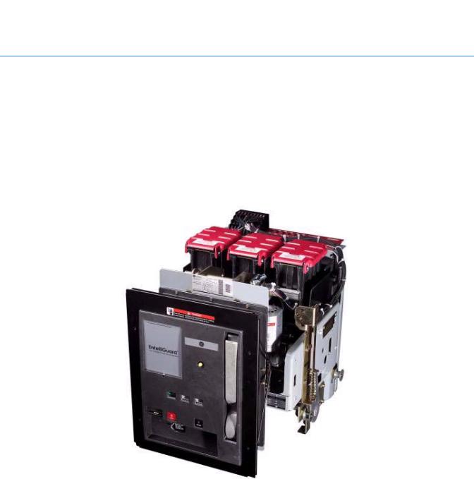
1.3.1 EntelliGuard circuit breaker
EntelliGuard low-voltage power circuit breakers control and protect power circuits up to 600 volts. They will safely switch loads and automatically clear circuits when abnormal conditions occur. These include short circuits, sustained overloads, ground faults, and other programmable conditions.
The EntelliGuard circuit breakers are available in 800 ampere, 1,600 ampere, 2,000 ampere, 3,200 ampere, 4,000 ampere, and 5,000 ampere frame sizes. These values represent the maximum continuous-current rating of each frame.
Circuit breakers may be equipped with a combination of accessories and interlocking devices.
Figure 1-3 EntelliGuard small frame circuit breaker
•The network interlock accessory selectively prevents the closing of specific circuit breakers in the electrical distribution network. The CPU sets and resets network interlock devices remotely while continuously monitoring their status. For example, in a double-ended substation, these devices could be used to interlock the main and tie circuit breakers to prevent connecting two unsynchronized power sources.
•The bell alarm lockout accessory prevents a circuit breaker from closing after receiving a trip command from the EntelliGuard Messenger. Closing of the circuit breaker is permitted only after the lockout is reset manually at the front of the circuit breaker.
For more information, see the following EntelliGuard Circuit Breaker Instruction Books:
•DEH-201 EntelliGuard Power Circuit Breakers 800-2,000A Frames, 240-600Vac Users Guide
•DEH-202 EntelliGuard Power Circuit Breakers 3,200-5,000A Frames, 240-600Vac Users Guide
System components |
15 |

1 1.3.2 Current transformers
Current transformers (CTs) are sensors that measure current. Each circuit breaker requires input from three CTs (one per phase) and an optional neutral CT. Unlike traditional switchgear, this single set of CTs provides the necessary current sensing for all needs including protection, metering, and control.
The CTs are attached to the power bus behind the circuit breaker in the circuit breaker compartment. Only Entellisys CTs may be used with the Entellisys system.
CTs either come in a 3-pack (shown in Figure 1-4) or as single CTs.
Figure 1-4 CT 3-pack
16 System architecture
|
|
1 |
1.3.3 Potential transformers |
||
|
|
|
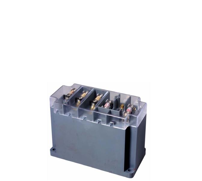
Potential or voltage transformers (PTs) are sensors that measure voltage. Unlike traditional switchgear, only the main (or source) circuit breakers in the system require PTs. This hardware and wiring reduction is possible because of the central processor architecture and the sampling synchronization maintained by the system.
Three PTs, one for each phase, are required on the main circuit breakers in the system. The remaining circuit breakers reference one circuit breaker with physical PTs and use that source's voltage readings for metering calculations. This source reference may change as the system topology changes.
The PTs are located outside the circuit breaker compartments in auxiliary compartments.
Figure 1-5 Entellisys PT
System components |
17 |
1 1.3.4 EntelliGuard Messenger
The EntelliGuard Messenger electronic device provides the interface between the circuit breakers and the CPUs in the Entellisys system.
The following is a summary of the Messenger’s functionality:
• Digitizes all switchgear signals
• Communicates the raw samples to CPUs via the Messenger network
• Controls the circuit breaker
• Performs independent backup trip capability at all times
• Powered by dual 120v control power sources or self-powered from the current sensors
• Provides LED illumination of circuit breaker status, power status, communication status, and GE “Locator” information
• Provides seal-able switches to set CT rating, and (long time) multiplier setting
• Provides a test connector for trip curve testing using the Entellisys System Test Kit
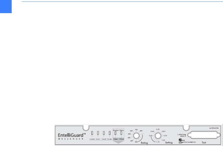
1.3.4.1 Messenger User Interface
The Messenger User Interface, as show in Figure 1-6, is described below.
Figure 1-6 Messenger front
LED Indicator Lights
•Locate: LED blinks for 10 or 30 seconds on command from the HMI to help operator physically locate a circuit breaker in the switchgear lineup.
•Com1, Com2: Illuminates when Ethernet communication is plugged in and ready to communicate.
•Power: Illuminates when either Control Power A or Control Power B sources are powering the messenger.
•Circuit Breaker Status Open: Illuminates when the circuit breaker is Open. This sensor is independent of the circuit breaker Close sensor.
•Circuit Breaker Status Closed: Illuminates when the circuit breaker is Closed. This sensor is independent of the circuit breaker Open sensor.
Switches
•Rating: Ampere rating of the circuit in use. Maximum value is the CT Rating.
•Setting: Multiplier setting for Long Time Overcurrent Protection, specified as X times the Rating switch value.
Rating Label
•Frame: Circuit breaker frame size, in Amperes, represents the maximum continuous-current rating.
•CT: Maximum Ampere rating of the CTs.
18 System architecture

Test Connector |
1 |
Connection point between the Entellisys System Test Kit and the Messenger. |
Figure 1-7 EntelliGuard Messenger
The Messenger is located directly above the circuit breaker compartment.
1.3.5 Compartment ID button
The Compartment ID button stores compartment configuration information in non-volatile memory. It informs the system about the circuit breaker residing in the cubicle.
The Compartment ID button is shipped inserted into the EntelliGuard Messenger, tethered to the equipment, and does not require any user interface during normal operation. It remains within the switchgear cubicle at all times.
WARNING! Compartment ID buttons are set at the factory and are not interchangeable between compartments. Failure to utilize the correct compartment ID button can result in personal injury and damage to equipment.
The ID button provides the system with necessary information such as circuit breaker frame size, CT size, and overcurrent protection capabilities as follows:
•Ground fault protection always on
•Ground fault protection always off
•Ground fault protection switchable (enabled/disabled) in the HMI
If the ground fault protection options need to change, a replacement ID button must be ordered (GE CAT# ETSCOMPID).
System components |
19 |

Figure 1-8 Compartment ID Button un-tethered from switchgear
1
1.3.6 Messenger communications network
The Messenger communications networks are closed, dedicated LANs for transmitting information between the Messengers and the CPUs in the system. The LANs are for the Entellisys system only and should never be connected to other networks.
CAUTION: Failure to maintain a dedicated LAN will result in the EntelliGuard Messenger reverting to back-up Overcurrent protection.
A Messenger switch is required to route information appropriately. The communication wiring required is 100BaseT, CAT5 cables.
Each CPU resides on a separate network, providing redundant communications.
1.3.7 Messenger switch
The Messenger switch enables the communication network between the Messengers and corresponding CPU. A Messenger switch is required for each of the two redundant networks. The number of ports provided is determined by the number of circuit breakers in the system. Each circuit breaker requires its own port in the switch.
The largest switch provides only 24 ports. If the number of circuit breakers in the system exceeds 22, a pyramid switch scheme, utilizing multiple switches, is required.
20 System architecture
|
|
1 |
1.3.8 CPU |
||
|
|
|
The CPU is a rack-mount industrial computer running a real-time operating system. The CPU provides the processing capability to support all switchgear functions. Two redundant CPUs (CPU A and CPU B) are used per lineup, supporting up to 30 circuit breakers.
The CPUs run simultaneously. If one CPU has an issue, the other continues to run providing redundancy. One CPU should be running at all times to maintain the highest level of protection. In the event that the Messenger-to-CPU communication network is down or power to the CPU is not available, the EntelliGuard Messenger will provide back-up overcurrent protection functionality.
The redundant CPUs are synchronized by a common connection to a synch clock. Each CPU has a slot for synch clock, although only one synch clock is used per system. The synch clock is programmed for either 60 Hertz or 50 Hertz frequency operation.
Each CPU has two slots for optional discrete I/O cards.
Figure 1-9 Redundant CPUs with synch clock connection
1.3.9 Synch clock
To maintain system synchronization, a mechanism exists to provide a single sampling time source. This time source is provided on a separate hardware card, called the Synch Clock. The Synch Clock sits in CPU A and has a connection to CPU B.
In the event of an issue with the Synch Clock or its connections, the CPUs fall-back to software synch functionality. When this occurs CPU A maintains full functionality. As time drifts, CPU B may suspend advanced multi-source protection and may not be able to provide metering information for the circuit breakers without PTs. If CPU A is powered down to provide maintenance, CPU B will continue to run all functions.
System components |
21 |

1 1.3.10 Discrete I/O
The discrete I/O equipment provides programmable input and output logic for customer-specific requirements.
Examples include the following:
• Sound a horn when a circuit breaker is open
• Trigger an output when voltage exceeds a value
The redundant discrete I/O option provides signal processing to/from either CPU. One CPU (the Master) processes the information and responds. The other provides a backup of the Master fails. Redundant discrete I/O is recommended if any of the signals are critical to the operation of the system. Critical I/O examples include the following:
• Inputs to automatic throw-over schemes
• Inputs that must trip circuit breaker (such as high transformer pressure) For more information on discrete I/O, see Discrete I/O on page 149.
1.3.10.1 Discrete I/O cards
The input and output signals from the CPU are transferred through the discrete I/O cards. Each card supports 64 bi-directional points that range from 0 to 5 volts. A maximum of two cards may be inserted for a total of 128 I/O points. The cards come installed in the CPU upon purchase.
1.3.10.2 Discrete I/O cable
This cable connects the discrete I/O card to the terminal block. Each cable transmits 64 I/O points.
1.3.10.3 Terminal block
The terminal block accepts 64 I/O signals from the discrete I/O card through a single cable and breaks out the individual signals into 64 terminals for wiring.
1.3.10.4 “OR” boards
These boards are only required for redundant discrete I/O. The output signals from both CPUs must be “Horde” together, between the terminal blocks and the relay blocks, to prevent increased voltages from damaging the relays. Each “OR” board supports 16 output signals.
1.3.10.5 Relay blocks
The relay blocks hold solid state input and output relays (16 per block).
Relay blocks are configured as all inputs or all outputs. Unused discrete I/O points may have relays left off.
1.3.10.6 Relays
The input relays transform the customer input (120 Vac or 24-125 Vdc) to 5V inputs for the
Entellisys system.
The output relays are either opened or closed based on programmable logic in the Entellisys system.
22 System architecture
1.3.10.7 Discrete I/O customer interface wiring
The customer interface to the discrete I/O is provided at the I/O module relay blocks. These relay blocks and the customer wire termination points are mounted in the discrete I/O cubicle and are accessed from the front of the switchgear. Control conduits are terminated in the rear cable compartment and the discrete I/O wiring is routed to the front of the switchgear through an opening in the discrete I/O cubicle rear barrier.
1
1.3.11 System interface Ethernet communication network
The system interface Ethernet communication network is a 10/100 Mbps Ethernet LAN that provides an interface into the Entellisys system for systems such as the Entellisys HMI, SCADA systems, building automation, HVAC systems or other. The system interface Ethernet communication network provides information and control of all circuit breakers in the system. The external communications network will use 100BaseT (copper twisted pair) CAT5 or better cabling. A fiber optic connection is available as an option.
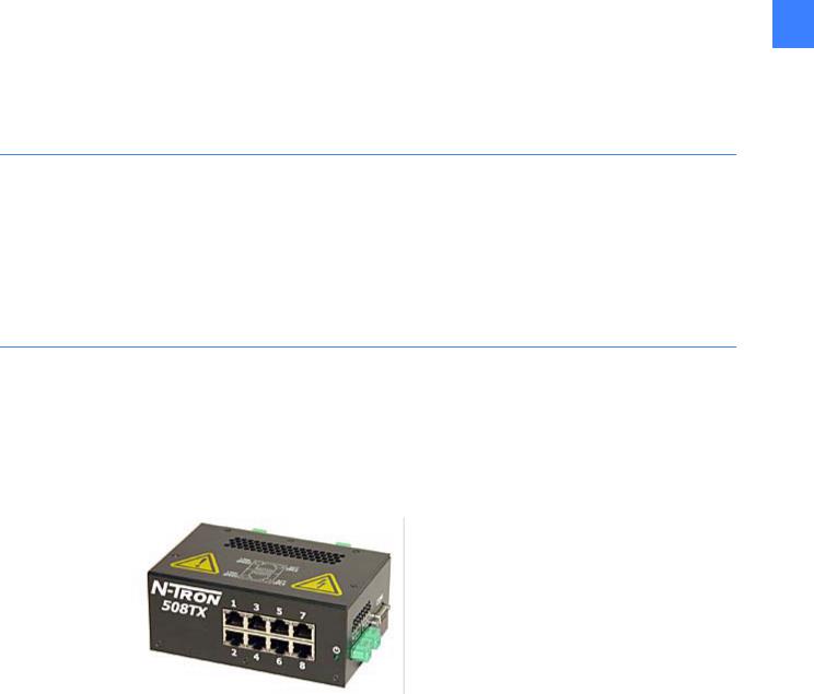
1.3.12 System interface Ethernet switch
The interface between the Entellisys system and the external world is through the system interface Ethernet switch, an industrial hardened 10/100 Mbps Ethernet switch. An 8-port copper model is standard. Optionally customers may choose a 9-port model with an additional fiber port for external gear communication. The fiber port supports 100FL connections only.
Figure 1-10 Ethernet switch, 8-port
System components |
23 |

1 1.3.13 Touchscreen HMI
The system interface for the Entellisys switchgear will be through one or more touchscreen computer displays. The display is driven by a separate computer and communicates to the CPUs through an Ethernet connection. The System Interface Ethernet Switch provides the physical interface.
The HMI communicates primarily with one of the CPUs but can switch to the other in event of a failure. Functionality provided by the HMI includes:
•Programmable user login to grant/deny access to specific features
•Animated one-line that shows the current status of the entire system
•Circuit breaker status, circuit breaker control
•Metering, demand logging, harmonics
•User settings for overcurrent protection, relay protection, advanced multi-source protection. This may be writable or read-only depending on permissions granted.
•Customer-specific discrete I/O programming and status
•Customer-specific control scheme programming and status
•Sequence of events
•System health – showing the health of the Entellisys equipment
•Alarm panel – setup, panel status, e-mail configuration for alarms
NOTE: The HMI is not critical to the protection functionality of the system. The HMI can be brought down for service with no loss of protection in the system.
1.3.13.1 In-gear HMI
Typically a touchscreen HMI is installed in the switchgear. This is deemed an “in-gear” HMI.
A redundant in-gear HMI is available as an option. The redundant HMI is also a touchscreen HMI located in the gear.
1.3.13.2 Near-gear HMI
Optionally, a touchscreen HMI may be installed near the switchgear equipment, but away from the hazardous arc flash zone. This can be in a separate stack or in a wall-mount box up to
250 feet from the switchgear. This is deemed a “near-gear” HMI.
24 System architecture

|
|
1 |
1.3.14 Remote HMI |
||
|
|
|
The Entellisys system offers desktop access to the switchgear with the same HMI software installed in the gear. The remote HMI software can be installed on any Windows 2000 desktop computer and requires an intranet connection to the switchgear. The intranet connection is connected to the system interface Ethernet switch.
Two versions of remote HMI are offered:
•User Interactive
Permissions are programmable and can be set for full Administrator access down to Guest access.
•Viewer
Allows read-only access to the system.
1.3.15VPN firewall device
Virtual Private Network (VPN) firewall device provides business-class network security providing Denial of Service (DoS) protection and intrusion detection using Stateful Packet Inspection (SPI), URL access and content filtering, logging, reporting, and real-time alerts. Up to eight users can access the system simultaneously.
It is strongly recommended that anytime an Entellisys system is connected to the intranet, a
VPN firewall be installed to protect the Entellisys system from network threats.
For more information, see DEH-430 Entellisys Low Voltage Switchgear System Administrator
Manual.
1.3.16 Control power
Control Power is 120 Vac, 50 and 60 Hz only. Uninterruptible power is provided standard with each system. The control power scheme is specific to each installation and constructed from standard elements using defined practices for Entellisys control power distribution.
1.3.17 UPS
Two Universal Power Supplies are installed in the switchgear to provide backup power to the control power network. The UPSs are powered from the primary power buses (utility or generator) and are redundant.
The UPS serves all 120 Vac control power network devices. It does not power the charging motors of electrically operated circuit breakers.
For more information on the Control Power Network, see Control power and UPS configuration on page 209.
For more information on the UPS, see the “GE Digital Energy GT Series™ - UL, Product
Description” at www.gedigitalenergy.com.
System components |
25 |

1 |
|
|
|
1.3.18 UPS to HMI connection |
|
|
|
The Entellisys system provides event/alarm/e-mail information when the UPS A has gone on |
|
|
|
|
|
battery backup and when the batteries are low. When the batteries are low, the HMI safely shuts |
|
|
down to avoid abrupt power interruption. To enable this communication, a link between UPS A |
|
|
and the primary touchscreen HMI is established. This link is a serial connection between the |
|
|
DB-9 serial port connection on the UPS and the DB-9 serial port connection on the HMI. Since |
|
|
distances between the HMI and UPS may exceed serial cable distances, a pair of RS-232 to |
|
|
RS-485 converters are installed at each end to accommodate the cabling distance through the |
|
|
switchgear. |
1.3.19 RS-232 to RS-485 converter
This device converts RS-232 signals to RS-485 signals. This is required to support the cable lengths in the switchgear. RS-232 imposes a distance limitation of only 15 meters. RS-485 can transmit data over distances up to 1.2 km.
1.3.20 Entellisys System Test Kit
The Entellisys System Test Kit is a portable test instrument designed for field testing of the Entellisys Low-Voltage Switchgear system.
The test kit includes the following features:
•Simulate power-line characteristics for a single circuit breaker in the Entellisys Low-Voltage System
•Verify the function/operation of the protection system
•Overcurrent protection tests – long time, short time, instantaneous and ground fault protection tests
•Single point relay protection tests (overvoltage, undervoltage, over frequency, under frequency, power reversal and phase loss, high current test)
•Verify the calibration of the trip time current curve
•Verify the operation of the circuit breaker actuation in “Trip mode”
•Perform tests without trips in “No Trip mode”
•Ground Fault Defeat function provides temporarily suspension of all ground fault protection in the system
•Automatically retrieves system configuration for increased productivity
•Displays a summary of all protection configuration
•Saves test results to be reviewed later
•Windows Interface for ease of use
•Operation from 120 Vac
For more information, see DEH-233 Entellisys Low Voltage Switchgear System Test Kit User
Manual.
1.3.21 Clamp circuit
The clamp circuit is an intermediary device between the CTs with 150ampere and 400ampere ratings only. The clamp circuit protects the Messenger from large current outputs from the CTs. The clamp circuit is installed in the circuit breaker compartment on the left-hand side sheet.
26 System architecture

2 Specifications
2
2.1 Environmental
Storage/shipping temperatures
–40 to 85° C
Operating temperatures
0 to 40° C ambient, indoor use
Humidity
5% to 95%, non-condensing, indoor use
2.2 Type tests
Tests are split into two categories:
•EntelliGuard Messenger Tests – the primary protection control element
•Entellisys System Tests – the complete system
Table 2-1 Type tests
Type |
Name |
EntelliGuard Messenger |
Entellisys System Tests |
|
|
Tests |
|
|
|
|
|
EMC/Transient |
Harmonic Currents |
IEC60947-2 sec.F.4.1.2 |
|
|
|
|
|
EMC/Transient |
Current Dips and |
IEC60947-2 sec. F.4.2 |
|
|
Interruptions |
|
|
|
|
|
|
EMC/Transient |
Fast Transient Burst |
IEC61000-4-4 |
ANSI C37.90.1 |
|
|
ANSI C37.90.1 |
ANSI C62.41 |
|
|
|
IEC61000-4-4 |
|
|
|
|
EMC/Transient |
Voltage/Current Surge |
IEC61000-4-5 |
ANSI C62.41 |
|
Immunity |
IE255-22-5 |
IEC61000-4-4 |
|
|
|
|
EMC/Transient |
Electrostatic Discharge |
IEC60947-2 sec. F.4.3 |
EN61000-4-2 |
|
Immunity |
IEC60255-6 |
|
|
|
|
|
EMC/Transient |
1MHz Oscillatory SWC |
IEC 60255-22-1 |
ANSI C37.90.1 |
|
|
ANSI C37.90.1 |
|
|
|
|
|
EM emission |
Conducted |
|
FCC part 15, subpart B, Class A |
|
|
|
|
EM emission |
Radiated |
|
FCC part 15, subpart B, Class A |
|
|
|
|
RFI |
Electromagnetic Field |
IEC60947-2 sec. F.4.4 |
|
|
Immunity |
|
|
|
|
|
|
Environmental 27

Table 2-1 Type tests
|
|
Type |
Name |
EntelliGuard Messenger |
Entellisys System Tests |
|
|
|
|
Tests |
|
2 |
|
|
|
|
|
|
|
|
|
|
|
|
RFI |
RFI with portable |
IEC60255-6 |
|
|
|
|
|
|||
|
|
|
transmitters |
|
|
|
|
|
|
|
|
|
|
RFI |
ANSI Radiated |
ANSI C37.90.2 |
ANSI C37.90.2 |
|
|
|
Susceptibility |
|
|
|
|
|
|
|
|
|
|
RFI |
Conductive RF Immunity |
IEC60255-22-6 |
|
|
|
|
|
|
|
|
|
Environment |
Dry Heat |
IEC60947-2 sec. F.7 |
|
|
|
|
|
|
|
|
|
Environment |
Thermal Shock |
IEC60947-2 sec. F.9 |
|
|
|
|
|
IEC60068-2-1 |
|
|
|
|
|
IEC60068-2-2 |
|
|
|
|
|
|
|
|
|
Environment |
Damp Heat |
IEC60947-2 sec. F.8 |
|
|
|
|
|
|
|
|
|
Environment |
Humidity |
IEC60947-1 |
|
|
|
|
|
IEC60947-2 sec. F.8 |
|
|
|
|
|
|
|
|
|
Mechanical |
Sinusoidal Vibration |
IEC255-21-1 |
|
|
|
|
|
|
|
|
|
Safety |
Dielectric Strength |
IEC60255-6 |
ANSI C37.20.2 Paragraph 5.3 |
|
|
|
|
|
|
|
|
Safety |
Insulation Resistance |
IEC60255-6 |
|
|
|
|
|
|
|
|
|
Safety |
Impulse Voltage Withstand |
IEC60255-6 |
|
|
|
|
|
|
|
|
|
Magnetic |
Power Frequency |
IEC61000-4-8 |
|
|
|
|
Magnetic Field |
|
|
|
|
|
|
|
|
|
|
Magnetic |
Power Magnetic Field |
IEC61000-4-9 |
|
|
|
|
Immunity |
|
|
|
|
|
|
|
|
|
|
Voltage |
Overvoltage |
|
ANSI C84.1 |
|
|
|
|
|
IEC 61000-4-11 |
|
|
|
|
|
|
|
|
Voltage |
Undervoltage |
|
ANSI C84.1 |
|
|
|
|
|
|
|
|
Voltage |
Ramp voltage |
|
ANSI C84.1 |
|
|
|
|
|
|
|
|
Voltage |
Line Interruption |
|
ANSI C84.1 |
|
|
|
|
|
IEC 61000-4-11 |
|
|
|
|
|
|
2.3 Approvals
UL Listed – Low Voltage AC Power Circuit Breaker Trip Unit - E-48428
FCC Class A listed
28 Specifications

3 HMI Basics
3.1 Entellisys HMI Overview |
3 |
When the user approaches the HMI, the HMI is logged in as guest and the default screen will be displayed.
Figure 3-1 One-Line diagram
Entellisys HMI Overview |
29 |
3.1.1 The Header Pane
Figure 3-2 The header pane
3
Navigation buttons
Forward and back buttons
Opens a dynamic floating menu. The menu options very depending on the current login credentials
On-line help
About - displays current HMI software revision
Login/Logout
Standard Display Screen buttons
Each of the status screens below are viewable before logging into the system.
•One-Line
•Elevation
•Control Status
•Events
•System Health
•Alarm Status
Enables/disables Reduced Energy Mode, see Reduced Energy Let-Thru Mode on page 129
30 HMI Basics
Loading...