


GEH–6281E
g
Power Break® II Circuit Breaker Accessories
Motor Operator Mechanism
Introduction |
Remote Operation |
The Motor Operator Mechanism, shown in Figure 1, can be installed in 800–4000 A frame Power Break® II circuit breakers. It provides a means of remotely or automatically charging the springs that close the breaker. Table 1 lists the catalog numbers and corresponding electrical data for the available models. Note that the Remote Close and Shunt Trip accessories are not included with the Motor Operator Mechanism; they must be ordered separately.
The circuit breaker closing springs can be charged remotely by shorting terminals 17 and 35 on the terminal block on the right side of the breaker, with a push button or similar device, for a minimum of five seconds. Power for the Motor Operator must also be applied to terminals 18 and 36, as shown in the wiring diagram in Figure 6.
Automatic Operation
Connect terminals 17 and 35 on the terminal block on the right side of the breaker with a jumper wire. The Motor Operator will automatically recharge the breaker closing springs whenever the breaker closes.
CAUTION: Do not wire breakers for both automatic charge and automatic close.
ATTENTION: Ne pas câbler les disjoncteurs pour tous les deux l’armement automatique et la fermeture automatique.
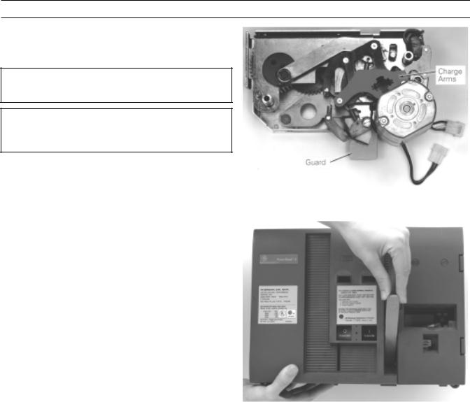
Figure 1. Motor Operator Mechanism.
|
|
Control |
|
|
|
|
|
|
|
|
|
|
|
Rated Voltage |
|
|
Peak |
|
|
|
(50–60 Hz) |
Voltage |
Peak Inrush |
Full-Load |
Average |
Charge Time |
Recommended |
|
Rating |
Current, A |
Current, A |
Current, A |
(sec) |
Fuse (Slo-Blo) |
24 Vdc |
21–27 Vdc |
30.0 |
14.0 |
11.0 |
3.0 (nom) |
12 A, 125 V |
|
|
|
|
|
|
|
48 Vdc |
41–53 Vdc |
18.0 |
7.0 |
4.5 |
3.0 (nom) |
7 A, 125 V |
72 Vdc |
62–80 Vdc |
10.0 |
4.5 |
3.0 |
3.0 (nom) |
5 A, 125 V |
120 Vac |
102–132 Vac |
7.5 |
4.0 |
2.0 |
3.0 (nom) |
4 A, 125 V |
125 Vdc |
106–137 Vdc |
8.0 |
2.5 |
1.8 |
3.0 (nom) |
2.5 A, 125 V |
240 Vac |
204–264 Vac |
6.0 |
2.5 |
1.0 |
3.0 (nom) |
2.5 A, 250 V |
Charging times apply to nominal voltage only; times may vary at maximum and minimum voltages.
Table 1. Electrical data for the Motor Operator Mechanism.
Power Break® II Motor Operator Mechanism
Installation in 800–4000 A Stationary Breaker
Installation in 800–4000 A Stationary
Breaker
WARNING: Before installing any accessories, turn the breaker off, disconnect it from all voltage sources, and discharge the closing springs.
AVERTISSEMENT: Avant d’installer tout accessoire, mettre le disjoncteur en position OFF, le déconnecter de toute tension d’alimentation, et décharger les ressorts d’armement.
Use the following procedure to install the Motor Operator Mechanism onto a stationary circuit breaker.
1 . Verify that the rating on the Motor Operator Mechanism identification plate matches the voltage rating required for the application, as listed in Table 1.
Figure 2. Motor Operator Mechanism charge arms in the discharged position.
2 . Check that the package contains all the parts listed in Table 2. If any components are missing, contact the ED&C Customer Support Center at 800-843- 3742. Note that the Remote Close and Shunt Trip accessories are not included with the Motor Operator Mechanism; they must be ordered separately.
Description |
Quantity |
|
|
|
|
Motor Operator Assembly |
1 |
|
|
|
|
1⁄4 |
-20 x 3-inch Flat-Head Screw |
2 |
1⁄4 |
-inch Conical Lock Washer |
2 |
Mounting Bracket |
1 |
|
#10-32 x 1⁄4 inch Screw |
6 |
|
#10 Lock Washer |
6 |
|
Labels |
2 |
|
Table 2. Parts list for the Motor Operator Mechanism.
3 . Verify that the charge arms of the Motor Operator Mechanism are in the discharged position, as illustrated in Figure 2.
4 . Turn the breaker off and discharge the closing spring by depressing the OFF and ON buttons in the sequence OFF-ON-OFF. Verify that the breaker OFF-ON indicator shows OFF on a green background and that the charge indicator shows DISCHARGED on a white background.
5 . Loosen the four #8-32 screws on the trim-plate assembly and remove the trim plate.
6 . Loosen the four screws at the corners of the breaker cover. Crank the operating handle one time and hold it extended to remove the cover from the breaker face, as illustrated in Figure 3. The Motor Operator can be safely installed with such a partially charged mechanism.
Figure 3. Removal of the breaker top cover.
7 . Remove the screw holding the left secondary terminal block to the midcover and lift the terminal block up and away from its mounting ridge on the midcover.
8 . Install the Remote Close accessory at this time if the breaker is to be equipped with this option.
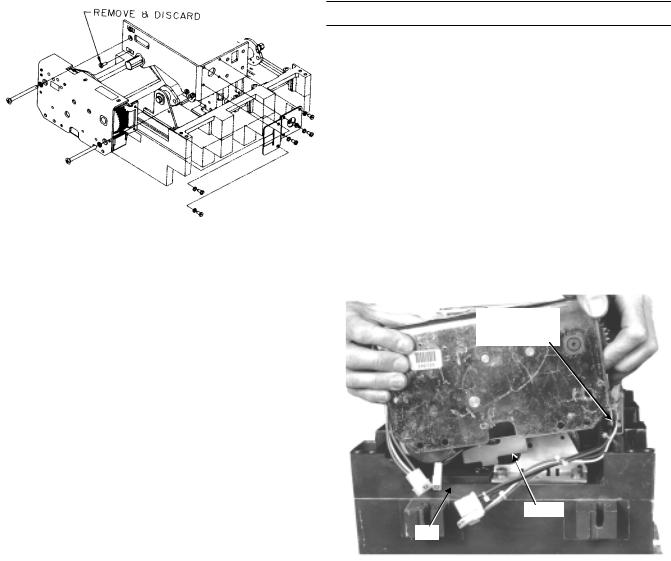
9 . Remove and discard the bottom screw, shown in Figure 4, that attaches the stop block to the spring frame.
10. Position the charge interlock rod of the breaker down against the midcover.
11. While holding the charge arm of the Motor Operator Mechanism in the discharged position, align the splined closing shaft of the breaker with the splined cutout in the hub of the charge arm, as shown in Figure 4. Tilt the right end of the mechanism up so that the guard (see Figure 2) clears the lip on the side of the breaker, as shown in Figure 5. Push the Motor Operator Mechanism in past the lip, rotate it back down, then push it
2
Power Break® II Motor Operator Mechanism
Installation in 800–4000 A Stationary Breaker
onto the breaker until the spacers engage the spring frame and the stop block.
12. Attach the Mounting Bracket to the four holes |
|
|
opposite the stop block on the spring frame with |
|
|
#10-32 screws tightened to 32 in-lb torque. The |
|
|
bend of the bracket must be outward from the |
|
|
spring frame. |
|
|
13. Align the two holes in the Mounting Bracket with |
|
|
the two holes in the Motor Operator Mechanism |
|
|
and attach with two #10-32 screws tightened to 32 |
|
|
in-lb torque. |
|
|
14. Thread a 1⁄4–20 flat-head screw and conical lock |
|
|
washer through the spacer and into the stop block, |
|
|
as illustrated in Figure 4. Thread the other 1⁄4–20 |
|
|
flat-head screw and conical lock washer through |
|
|
the spacer into the captive nut in the spring frame. |
Figure 4. Installing the Motor Operator Mechanism onto the breaker. |
|
Tighten both screws to 70 in-lb. |
||
|
15. Plug the color-coded, numbered Motor Operator Mechanism wires into the corresponding numbered sockets, as illustrated in Figure 6. Mating connector wires are installed at the factory and are located in the gray-painted channel, shown in Figure 5
16. Dress the wires and install cable ties as shown in the illustration in Figure 7. Ensure that wires are clear of all moving parts.
17. Reinstall the secondary terminal block onto the breaker midcover terminal block mounting ridge and fasten with the screw previously removed.
18. Crank the operating handle once and hold the handle extended to reinstall the breaker top cover. Tighten the four #10-32 mounting screws to 15 in-
lb.
Lip
19. Replace the trim plate and tighten the four #8-32 screws to 20 in-lb.
Motor Operator
Wires in Gray
Channel
Guard
20. Affix the accessory rating label to the breaker cover above the right-side secondary terminal block.
21. Affix the “Electrically Operated” label to the top cover over the knock-out space above the ON-OFF indicator flag.
22. Crank the operating handle until the closing springs are completely charged.
23. Close and trip the breaker.
24. Test the Motor Operator Mechanism electrically according to Table 1.
Figure 5. Rotating the Motor Operator Mechanism so that the guard clears the lip on the side of the circuit breaker.
3

Power Break® II Motor Operator Mechanism
Installation in 800–4000 A Stationary Breaker
Figure 6. Wiring diagram of the Motor Operator Mechanism and Remote Close accessories.
Figure 7. Installing the Motor Operator wires.
4
 Loading...