


GE Energy
Industrial Solutions
GEH-702 Users Manual
Spectra® RMS Molded Case
Circuit Breakers
with microEntelliGuardTM Trip Units

GEH-702 Users Manual
Spectra® RMS Circuit Breakers with microEntelliGuardTM Trip Unit
The microEntelliGuardTM Trip Unit is the latest and most advanced trip unit available in the Spectra line of molded case circuit breakers. The trip unit design is based on the EntelliGuard trip unit platform. The microEntelliGuardTM Trip Unit incorporates many of the advanced features and protective functions available on the EntelliGuard Trip Unit and is available in the 600-amp Spectra G and 1200-amp Spectra K frames. Spectra breakers with microEntelliGuardTM Trip Units allow you to select the enhanced system protection, coordination, and communication options required for the application.
|
Standard Protection |
Advanced Protection |
Advanced Features |
||||||||||||||||||||||||||
|
Long Time |
Neutral Protection |
Metering (Basic/Advanced) |
||||||||||||||||||||||||||
|
Short Time |
Zone Selective Interlock (ST/GF/INST) |
Communications (Modbus) |
||||||||||||||||||||||||||
|
Instantaneous |
Reduced Energy Let-through |
Waveform Capture |
||||||||||||||||||||||||||
|
Ground Fault (trip or alarm) |
|
|
|
|
|
|||||||||||||||||||||||
|
Table 1. Catalog Number Nomenclature |
|
|
|
|
||||||||||||||||||||||||
|
|
|
|
|
|
|
|||||||||||||||||||||||
SK PC 36 12 L4 R 6 |
|
|
|
Function |
|
|
|||||||||||||||||||||||
|
|
|
|
|
|
|
|
|
|
|
|
|
|
|
|
|
|
|
|
|
|
|
|
Code |
Description |
|
|
||
|
|
|
|
|
|
|
|
|
|
|
|
|
|
|
|
|
|
|
|
|
|
|
|
SK |
SK1200 |
|
Frame Designation |
|
|
|
|
|
|
|
|
|
|
|
|
|
|
|
|
|
|
|
|
|
|
|
|
|
|
|
|||||
|
|
|
|
|
|
|
|
|
|
|
|
|
|
|
|
|
|
|
|
|
|
|
|
HC |
35kA at 480Vac |
|
Interruption Rating |
|
|
|
|
|
|
|
|
|
|
|
|
|
|
|
|
|
|
|
|
|
|
|
|
|
|
LC/TC1 |
65kA at 480Vac |
Standard UL Rating |
|
||
|
|
|
|
|
|
|
|
|
|
|
|
|
|
|
|
|
|
|
|
|
|
|
|
|
|
|
|||
|
|
|
|
|
|
|
|
|
|
|
|
|
|
|
|
|
|
|
|
|
|
|
|
PC/SC1 |
100kA at 480 Vac |
|
|
|
|
|
|
|
|
|
|
|
|
|
|
|
|
|
|
|
|
|
|
|
|
|
|
|
|
|
|
|
|||
|
|
|
|
|
|
|
|
|
|
|
|
|
|
|
|
|
|
|
|
|
|
|
|
HH |
35kA at 480Vac |
|
|
|
|
|
|
|
|
|
|
|
|
|
|
|
|
|
|
|
|
|
|
|
|
|
|
|
|
LL/TT1 |
65kA at 480Vac |
100% Continuous UL Rating |
|
|
|
|
|
|
|
|
|
|
|
|
|
|
|
|
|
|
|
|
|
|
|
|
|
|
|
PP/SS1 |
100kA at 480 Vac |
|
|
|
|
|
|
|
|
|
|
|
|
|
|
|
|
|
|
|
|
|
|
|
|
|
|
|
|
3, 4 or 6 |
3 Poles, 480Vac or 600Vac |
Poles, Max UL Voltage |
|
||
|
|
|
|
|
|
|
|
|
|
|
|
|
|
|
|
|
|
|
|
|
|
|
|||||||
|
|
|
|
|
|
|
|
|
|
|
|
||||||||||||||||||
|
|
|
|
|
|
|
|
|
|
|
|
|
|
|
|
|
|
|
|
08 |
800 Amps |
|
|
|
|
||||
|
|
|
|
|
10 |
1000 Amps |
SK Frame |
Max Amps |
|
||||||||||||||||||||
|
|
|
|
|
|
|
|
|
|
|
|
12 |
1200 Amps |
|
|
|
|
||||||||||||
|
|
|
|
|
|
|
|
|
|
|
|
|
|
||||||||||||||||
|
|
|
|
|
|
|
|
|
|
|
|
|
|
|
|
|
|
|
|
|
|
|
|
L3 |
LSI |
L = Long Time |
Standard Protection |
|
|
|
|
|
|
|
|
|
|
|
|
|
|
|
|
|
|
|
|
|
|
|
|
|
|
S = Short Time |
|
|
|||
|
|
|
|
|
|
|
|
|
|
|
|
|
|
|
|
|
|
|
|
|
|
|
|
|
|
|
|||
|
|
|
|
|
|
|
|
|
|
|
|
|
|
|
|
|
|
|
|
|
|
|
|
|
|
Functions |
|
|
|
|
|
|
|
|
|
|
|
|
|
|
|
|
|
|
|
|
|
|
|
|
|
|
|
L4 |
LSIG |
I = Instantaneous |
|
||
|
|
|
|
|
|
|
|
|
|
|
|
|
|
|
|
|
|
|
|
|
|
|
|||||||
|
|
|
|
|
|
|
|
|
|
|
|
|
|
|
|
|
|
|
|
|
|
|
|
|
|
|
|
|
|
|
|
|
|
|
|
|
|
|
|
|
|
|
|
|
|
|
|
|
|
|
|
|
|
L5 |
LSIA |
G = Ground Fault |
|
|
|
|
|
|
|
|
|
|
|
|
|
|
|
|
|
|
|
|
|
|
|
|
|
|
|
A = Ground Fault Alarm |
|
|
|
||
|
|
|
|
|
|
|
|
|
|
|
|
|
|
|
|
|
|
|
|
|
|
|
|
|
|
|
|
|
|
|
|
|
|
|
|
|
|
|
|
|
|
|
|
|
|
|
|
|
|
|
|
|
|
L7 |
LSI-CP |
CP = Control Power |
|
|
|
|
|
|
|
|
|
|
|
|
|
|
|
|
|
|
|
|
|
|
|
|
|
|
|
|
|
|
|
|
|
|
|
|
|
|
|
|
|
|
|
|
|
|
|
|
|
|
|
|
|
|
|
|
|
X |
None |
|
|
|
|
|
|
|
|
|
|
|
|
|
|
|
|
|
|
|
|
|
|
|
|
|
|
|
|
K |
Neutral Protection |
|
|
|
|
|
|
|
|
|
|
|
|
|
|
|
|
|
|
|
|
|
|
|
|
|
|
|
|
Z |
ZSI (ST/GF) |
|
|
|
|
|
|
|
|
|
|
|
|
|
|
|
|
|
|
|
|
|
|
|
|
|
|
|
|
T |
ZSI (ST/GF/INST) |
|
|
|
|
|
|
|
|
|
|
|
|
|
|
|
|
|
|
|
|
|
|
|
|
|
|
|
|
R |
RELT |
|
Advanced Protection |
|
|
|
|
|
|
|
|
|
|
|
|
|
|
|
|
|
|
|
|
|
|
|
|
|
|
|
|
||||
|
|
|
|
|
|
|
|
|
|
|
|
|
|
|
|
|
|
|
|
|
|
|
|
L |
ZSI (ST/GF) + RELT |
|
|
||
|
|
|
|
|
|
|
|
|
|
|
|
|
|
|
|
|
|
|
|
|
|
|
|
|
Functions |
|
|
||
|
|
|
|
|
|
|
|
|
|
|
|
|
|
|
|
|
|
|
|
|
|
|
|
M |
ZSI (ST/GF) + Neutral Protection |
|
|||
|
|
|
|
|
|
|
|
|
|
|
|
|
|
|
|
|
|
|
|
|
|
|
|
|
|
|
|||
|
|
|
|
|
|
|
|
|
|
|
|
|
|
|
|
|
|
|
|
|
|
|
|
N |
ZSI (ST/GF) + RELT + Neutral Protection |
|
|
|
|
|
|
|
|
|
|
|
|
|
|
|
|
|
|
|
|
|
|
|
|
|
|
|
|
V |
RELT + Neutral Protection |
|
|
|
|
|
|
|
|
|
|
|
|
|
|
|
|
|
|
|
|
|
|
|
|
|
|
|
|
P |
ZSI (ST/GF/INST) + RELT |
|
|
|
|
|
|
|
|
|
|
|
|
|
|
|
|
|
|
|
|
|
|
|
|
|
|
|
|
S |
ZSI (ST/GF/INST) + Neutral Protection |
|
|
|
|
|
|
|
|
|
|
|
|
|
|
|
|
|
|
|
|
|
|
|
|
|
|
|
|
W |
ZSI (ST/GF/INST) + RELT + Neutral Protection |
|
|
|
|
|
|
|
|
|
|
|
|
|
|
|
|
|
|
|
|
|
|
|
|
|
|
|
|
X |
Metering (Basic) |
|
Advanced Features & |
|
|
|
|
|
|
|
|
|
|
|
|
|
|
|
|
|
|
|
|
|
|
|
|
|
|
2 |
Metering (Basic) + Modbus |
|
|||
|
|
Communication |
|
|
|||||||||||||||||||||||||
|
|
|
|
|
|
|
|
|
|
|
|
|
|
|
|
|
|
|
|
|
|
|
|
6 |
Metering (Adv) + Modbus + Waveform Capture |
|
|||
|
|
|
|
|
|||||||||||||||||||||||||
|
8 |
Metering (Adv) + Modbus + Waveform Capture + Protective Relays |
|
|
|
||||||||||||||||||||||||
|
|
|
|
|
|
|
|
|
|
|
|
|
|
|
|
|
|
|
|
|
|
|
|
|
|
|
|
|
|
1. SKT and SKS catalog codes are optimized for selectivity and will carry a 480Vac maximum voltage rating.

GEH-702 Users Manual
Warnings, Cautions, and Notes as Used in this Publication
Warnings - Warning notices are used in this publication to emphasize that hazardous voltages, currents, or other conditions that could cause personal injury are present in this equipment or may be associated
with its use.
Warning notices are also used for situations in which inattention or lack of equipment knowledge could cause either personal injury or damage to equipment.
Cautions - Caution notices are used for situations in which equipment might be damaged if care is not taken.
Notes - Notes call attention to information that is especially significant to understanding and operating the equipment.
This document is based on information available at the time of its publication. While efforts have been made to ensure accuracy, the information contained herein does not cover all details or variations in hardware and software, nor does it provide for every possible contingency in connection with installation, operation, and maintenance. Features may be described herein that are not present in all hardware and software systems. GE Industrial Solutions assumes no obligation of notice to holders of this document with respect to changes subsequently made.
GE Industrial Solutions makes no representation or warranty, expressed, implied, or statutory, with respect to, and assumes no responsibility for the accuracy, completeness, sufficiency, or usefulness of the information contained herein. No warrantees of merchantability or fitness for purpose shall apply.
2

GEH-702 Users Manual
Table of Contents
Spectra RMS Circuit Breakers with microEntelliGuard™ Trip Unit ……………………………… 1
Section 1
Read This First ………………………………………………………… 5
Trip Unit Functions…………………………………………………… 5
Standard Protection Functions …………………………………… 5 Advanced Protection Functions …………………………………… 5 Advanced Features And Communications ……………….. 6
Rating Plugs……………………………………………………………… 6
Equipment Interfaces ……………………………………………… 8
Neutral Current Transformers ……………………………………… 8
Terminal Blocks ………………………………………………………………… 8
Distribution Cable Junction Boxes ……………………………… 9
Power Supplies ………………………………………………………………… 9
Voltage Conditioners …………………………………………………… 10 Voltage Modules …………………………………………………………… 11 Distribution And Extension Cables …………………………… 11 Auxiliary Switches ………………………………………………………… 11 Communications …………………………………………………………… 12 Reduced Energy Let-Through …………………………………… 12 Zone Selective Interlock ……………………………………………… 12
Section 2
microEntelliGuard™ Trip Unit ……………………………… 14
Overview ………………………………………………………………………… 14 HMI …………………………………………………………………………………… 14 Liquid Crystal Display and Power Requirements ….. 14 Led Status Indicator ……………………………………………………… 15 Trip Unit Operating Modes ………………………………………… 15 Setup Mode……………………………………………………………………… 15
Language (Standard) ………………………………………………… 16 Long Time Pickup (Standard)…………………………………… 16 Long Time Delay (Standard) ………………………………….... 16 Short Time Pickup (Standard) ………………………………… 17 Short Time Delay (Standard) ……………………………………. 17 Instantaneous Pickup (Standard)…………………………… 18 Reduced Energy Let-Through (RELT)
Instantaneous Pickup (Optional)………………………… 18 Ground Fault Pickup (Trip Or Alarm) (Optional)…… 18 Ground Fault Delay (Trip Or Alarm) (Optional) ……. 19 Zone Selective Interlock (ZSI) (Optional) ………………. 19
Neutral Protection Pickup (Optional) …………………… 20 Protective Relays (Optional) …………………………………… 20 Output Relays (Optional) ………………………………………… 21 Waveform Capture (Optional) ………………………………… 21 Frequency (Standard) ……………………………………………… 21 Potential Transformer Primary Voltage
(Optional) ……………………………………………………………….. 21 Potential Transformer Connection (Optional) …… 21 Power Direction (Optional) …………………………………….. 22 Phase Rotation (Standard) ……………………………………... 22 Thermal Memory (Standard) …………………………………… 22 Auxiliary Switch (Standard)……………………………………… 22 Modbus (Optional) ……………………………………………………. 22 Date And Time (Standard)…………………………………………22
Metering Mode ……………………………………………………………. 23 Operating Mode ………………………………………………………. 23 Current (On All Trip Units) ………………………………………. 23 Voltage (Advanced Metering Only)………………………… 23 Real Power (Advanced Metering Only) ………………… 23 Reactive Power (Advanced Metering Only) ………… 23 Apparent Power (Advanced Metering Only) ……… 23 Peak Power Demand (Advanced Metering Only) . 23 Energy (Advanced Metering Only) ………………………… 24 Frequency (Advanced Metering Only) ………………… 24 Power Factor (Advanced Metering Only)……………… 24
Settings Mode ……………………………………………………………….. 24 Setting Status ……………………………………………………………. 24 Pickup Status ……………………………………………………………. 24 Error Status ………………………………………………………………. 24 Version ………………………………………………………………………. 24 Comm Settings …………………………………………………………. 24
Events Mode …………………………………………………………………. 24
Appendix A. Display Screen Flow ………………………….. 25 Appendix B. Modbus Register Map ……………………….. 28 Appendix C. Breaker Harness Pin-Outs ……………….. 45 Appendix D. Metering …………………………………………….. 47 Appendix E. Troubleshooting. ……………………………….. 48
Appendix F. Replacing MicroVersaTrip with microEntelliGuard™………………………………………………. 49 Appendix G. Additional Information …………………….. 50
3

GEH-702 Users Manual
Table of Figures |
Table of Tables |
Figure 1. Typical Neutral CT Connection ……………………… 9
Figure 2. Typical Power Supply Connection
Using a Terminal Block ……………………………………………… 10 Figure 3. Typical RELT Wiring Diagram…………………………. 12 Figure 4. Typical microEntelliGuard System ……………….. 13 Figure 5. LED Location……………………………………………………… 14 Figure 6. Keypad Definition ……………………………………………. 14 Figure 7. Typical LCD Screen …………………………………………. 14 Figure 8. Long Time Pickup……………………………………………… 16 Figure 9. Long Time Delay ………………………………………………. 16 Figure 10. Short Time Pickup ………………………………………… 17 Figure 11. Short Time Delay with Slope Off…………………. 17 Figure 12. Short Time Delay Set to Maximum ……………. 17 Figure 13. Instantaneous Pickup …………………………………... 18 Figure 14. Ground Fault Pickup ……………………………………… 18 Figure 15. Ground Fault Delay ………………………………………. 19 Figure 16. System With Voltage Swap Cable ……………. 22
Figure 17. Signal Definitions 20-Pin Harness
(Breaker Pigtail)……………………………………………………………… 45
Figure 18. Signal Definitions 12-Pin Harness
(Breaker Pigtail)……………………………………………………………… 46 Figure 19. DB15 Connector …………………………………………… 46
Figure 20. MicroVersaTrip vs. microEntelliGuard Conversion……………………………………………………………………… 49
Figure 21. MicroVersaTrip Commnet Wiring ………………. 49
Figure 22. microEntelliGuardTM Modbus
Connection …………………………………………………………………… 50
Table 1. Catalog Number Nomenclature ……………………… 1 Table 2. Rating Plug Catalog Numbers…………………………… 7 Table 3. Harness Type Definition………………………………………. 8 Table 4. Neutral CT’s …………………………………………………………… 8 Table 5. Terminal Block Descriptions ……………………………… 8 Table 6. Junction Box Descriptions ………………………………… 9 Table 7. Power Supply Plate Catalog Numbers ……………. 9 Table 8. Voltage Conditioner Plate Assemblies ………….. 10 Table 9. Voltage Module Catalog Numbers………………….. 11 Table 10. Distribution Cable Harness Options …………….. 11 Table 11. Extension Cable Harness Options ……………….. 11 Table 12. Voltage Exchange Harness Options…………….. 11 Table 13. Auxiliary Switch Options ………………………………... 11 Table 14. LED Status Flash Sequence ………………………….. 15 Table 15. Nominal Time Delays………………………………………… 16 Table 16. Available Instantaneous Pickup…………………….. 18 Table 17. ZSI Settings ……………………………………………………….. 20 Table 18. Output Relay Group Assignments ………………… 21 Table 19. Waveform Capture Setup……………………………….. 21 Table 20. Setup Mode Programming …………………………….. 25 Table 21. Wye Configuration Metering………………………….. 27 Table 22. Delta Configuration Metering ………………………. 27 Table 23. Status Screen Definitions ………………………………. 28 Table 24. Event Mode Screen Definitions ……………………. 28 Table 25. Discrete Input, Function Code 2 …………………. 29
Table 26. Communication Parameters:
Modbus Function 3 (Read Only)………………………………… 30
Table 27. Communication Parameters:
Modbus Function 3 (Read/Write Parameters) ………. 31
Table 28. Communication Parameters:
Modbus Function 4 ……………………………………………………… 40
Table 29. Communication Parameters:
Modbus Function 5 ……………………………………………………… 44 Table 30. Metering Accuracy …………………………………………. 47
4

GEH-702 Users Manual
Section 1
Read This First
Proper circuit protection depends on setting up and installing the circuit breaker correctly. Do not attempt to energize the circuit breaker before thoroughly understanding all of the trip unit setup parameters and ensuring that they are set correctly and that associated equipment and interfaces are also installed and connected correctly.
Spectra breakers with microEntelliGuardTM Trip Units use rating plugs to set the breaker current rating. Ensure that an appropriately sized rating plug is installed into the trip unit prior to programming the trip unit. Failure to install a rating plug can result in unwanted trips. Installing a rating plug that is not intended for the frame rating can result in unwanted trips, and could result in improper protection.
When setting up the trip unit for the first time, use external 24Vdc control power (via external control power, test kit, or portable batter pack) to ensure that all protection parameters are programmed correctly.
CAUTION - Removal of the rating plug while the breaker is carrying current reduces the breaker’s current-carrying capacity to the minimum rating plug value of the current sensor. This may result in unwanted tripping.
NOTE - Trip Units as received may have settings that are undesirable for the specific application. Ensure that settings are appropriately adjusted before energizing the breaker.
Trip Unit Functions
This section describes the standard and advanced protective functions and the advanced features and communication capabilities offered on the microEntelliGuardTM Trip Unit.
Standard Protection Functions
Adjustable Long Time (pickup and time delay) is standard. Three different sets of curve shapes are available with slopes that mimic traditional MicroVersaTrip® long time curves (I2t), recursive thermal curves (thermal-mag circuit breaker) and fuse emulation (I4t).
Adjustable Short Time (pickup and time delay) is standard. An option to turn the short time function off is also included. Multiple slope functions are available with I2t IN or OUT.
Adjustable Instantaneous (pickup) is standard. Adjustable Ground Fault (pickup and time delay) is optional. This feature causes the breaker to TRIP when responding to a ground fault.
Adjustable Ground Fault Alarm (pickup and time delay) is optional. This feature causes the breaker to ALARM (programmable output contact closure) when responding to a ground fault (the breaker will NOT trip).
Advanced Protection Functions
Neutral Protection (pickup and time delay) is optional. This protection function is designed to protect
the neutral from an overload condition (typical in applications where there are harmonics).
Zone Selective Interlock (ZSI) is optional. Restraint signals are available on Short Time, Ground Fault and Instantaneous.
Reduced Energy Let-Through (RELT) is optional. This feature allows a second instantaneous pickup setting at a reduced level and is enabled via an external signal (contact closure or communications).
5

GEH-702 Users Manual
Advanced Features and Communications
Basic Metering is standard. The metering option displays current for all three phases.
Advanced Metering is optional. This feature displays current, voltage, real power, reactive power, apparent power, peak power demand, energy, frequency, and power factor for all three phases. Proper operation of the advanced metering function requires multiple system accessories including power supplies, voltage conditioners, junction boxes, and interconnect cables.
Modbus Communications is optional. The communications option allows the breaker/trip unit to communicate all breaker data to an outside network.
Waveform Capture is optional. This option stores eight cycles worth of data into digital memory that can be output via the trip unit’s DB-15 connector, or over the Modbus interface.
Two Programmable Output Contacts (two) are optional. This feature is included on breakers/trip units that are optioned with any of the following functions or features
•Ground Fault Alarm
•Zone Selective Interlock
•Reduced Energy Let-Through
•Protective Relays
Breakers/trip units optioned with any of the above features have a 20-pin harness/connector and require accessories that accommodate the 20-pin connector (see section on equipment interfaces).
Rating Plugs
The microEntelliGuardTM Trip Unit uses a rating plug to establish or change the current rating of the breaker. Each breaker frame/sensor combination has multiple rating plugs available that are interchangeable within the trip unit. Rating plugs available for microEntelliGuardTM Trip Units are shown in Table 2.
These rating plugs are compatible with EntelliGuard trip units. Note that the same rating plug catalog number can be used across multiple breaker sensor ratings. For example, GTP0150U0104 is a 150 amp-rating plug that can be used in the Spectra microEntelliGuardTM G frame with 150 amp or 400 amp sensors.
6

GEH-702 Users Manual
Table 2.Rating Plug Catalog Numbers |
|
|
|
|
|
|
|
|
|
||
|
|
|
|
|
|
|
|
|
|
|
|
|
|
|
|
SG (Max Amps) |
|
|
SK (Max Amps) |
||||
|
Rating Plug |
Trip |
150 |
|
400 |
|
600 |
800 |
|
1000 |
1200 |
|
Product Numbers |
Amps |
|
|
|
||||||
|
|
|
|
|
|
|
|
|
|
||
|
|
|
|
|
|
|
|
|
|
|
|
|
GTP0060U0101 |
60 |
X |
|
|
|
|
|
|
|
|
|
GTP0080U0101 |
80 |
X |
|
|
|
|
|
|
|
|
|
GTP01OOU0103 |
100 |
X |
|
|
|
|
|
|
|
|
|
GTP0125U0103 |
125 |
X |
|
|
|
|
|
|
|
|
|
GTP0150U0104 |
150 |
X |
|
X |
|
|
|
|
|
|
|
GTP0200U0204 |
200 |
|
|
X |
|
|
|
|
|
|
|
GTP0225U0306 |
225 |
|
|
X |
|
X |
|
|
|
|
|
GTP0250U0407 |
250 |
|
|
X |
|
X |
|
|
|
|
|
GTP0300U0408 |
300 |
|
|
X |
|
X |
X |
|
|
|
|
GTP0350U0408 |
350 |
|
|
X |
|
X |
X |
|
|
|
|
GTP0400U0410 |
400 |
|
|
X |
|
X |
X |
|
|
|
|
GTP0450U0612 |
450 |
|
|
|
|
X |
X |
|
X |
X |
|
GTP0500U0613 |
500 |
|
|
|
|
X |
X |
|
X |
X |
|
GTP0600U0616 |
600 |
|
|
|
|
X |
X |
|
X |
X |
|
GTP0700U0816 |
700 |
|
|
|
|
|
X |
|
X |
X |
|
GTP0750U0820 |
750 |
|
|
|
|
|
X |
|
X |
X |
|
GTP0800U0820 |
800 |
|
|
|
|
|
X |
|
X |
X |
|
GTP0900U1020 |
900 |
|
|
|
|
|
|
|
X |
X |
|
GTP1OOOU1025 |
1000 |
|
|
|
|
|
|
|
X |
X |
|
GTP11OOU1225 |
1100 |
|
|
|
|
|
|
|
|
X |
|
GTP1200U1232 |
1200 |
|
|
|
|
|
|
|
|
X |
7
GEH-702 Users Manual
Equipment Interfaces
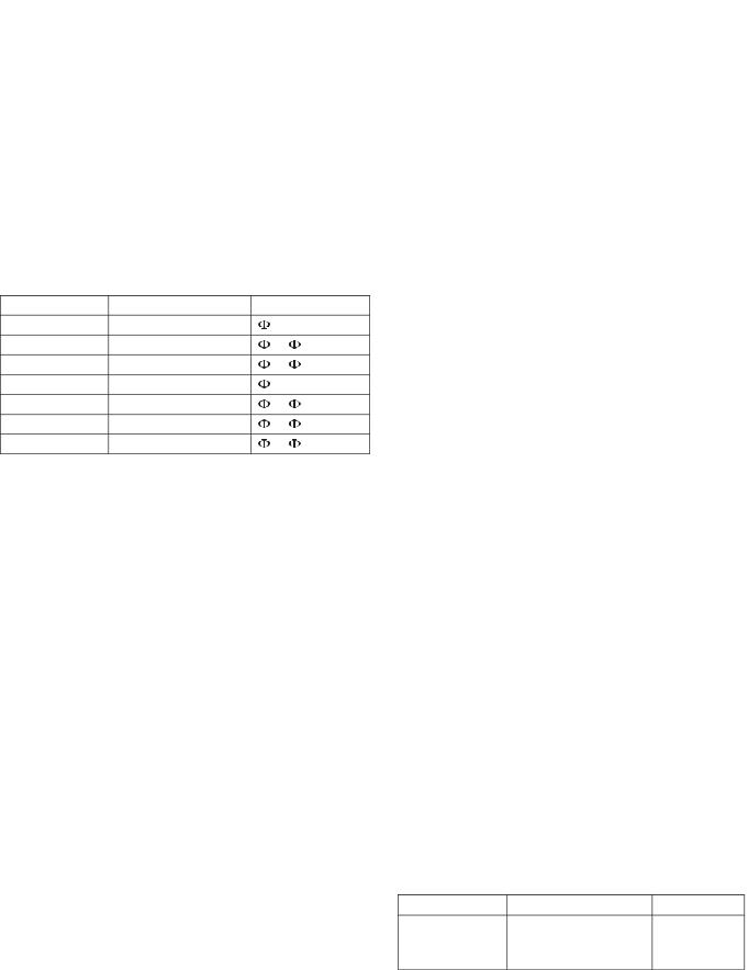
Equipment interfaces for Spectra microEntelliGuard™ breakers require special attention be paid to the wiring harness arrangement on the circuit breaker which depends on the features and functions that are selected for the microEntelliGuard™ Trip Unit. The three wiring harness arrangements are NO harness, 12-Pin harness, and 20-Pin harness. Table 3 identifies the harness arrangement based on the last four digits of the circuit breaker catalog number.
CAUTION: Neutral-current sensors are required for three-phase/four-wire and single-phase/three-wire systems. When the trip unit is connected to a three phase/three-wire system, the neutral-current sensor terminals are left open. Do not short any neutralcurrent sensor terminals in a three-phase/three- wire system, as this could result in damage to or malfunction of the electrical system.
Table 3. Harness Type Definition
|
Std. |
|
Adv. |
|
Adv. |
|
Protect |
|
Protect |
|
Features |
|
Function |
|
Function |
|
& Modbus |
Example: SGHC3601…. |
L3 |
|
X |
|
X |
|
|
|
|
|
|
No Harness |
L3 |
|
X |
|
X |
20-Pin Harness |
L5 |
|
Any |
|
Any |
20-Pin Harness |
Any |
|
Z,T,R, L,M,N, |
|
Any |
|
V,P,S,W |
|
|||
|
|
|
|
|
|
|
|
|
|
|
|
20-Pin Harness |
Any |
|
Any |
|
8 |
12-Pin Harness |
|
All Other Cases |
|
||
Note: Find the last four digits of the breaker catalog number in the table to identify the harness type.
Neutral Current Transformers
Neutral CT’s are required on breakers optioned for neutral protection. Neutral CT’s are also required on breakers optioned for Ground Fault/Ground Fault Alarm where the system voltage is three-phase/four-wire or single phase/three-wire. The list of available neutral CT’s is shown in Table 4.
Table 4. Neutral CT’s
Breaker |
Breaker Current |
Catalog |
Type |
Sensor Rating (S) |
Number |
|
150 |
TSRG201 |
SG |
400 |
TSRG204 |
|
600 |
TSRG206 |
|
800 |
TSKG408 |
SK |
1200 |
TSKG412 |
Connection to the neutral CT is made via a distribution cable terminal block (three options) or a distribution cable junction box (two options). Note: Terminal block and junction box selection depends on the breaker wiring harness, either a 12-Pin harness or 20-Pin harness. Refer to Figure 1 for an example neutral CT wiring connection diagram using a terminal block.
Terminal Blocks
Three different terminal block options are available for Spectra microEntelliGuardTM breakers. Breakers with a 12-Pin harness have one option for a terminal block where breakers with a 20-Pin harness have two terminal block options. The table below shows the terminal descriptions for each terminal block catalog number.
Table 5. Terminal Block Descriptions |
|
|
|
|
|
Termi al |
CTB |
CTB |
C |
CTB |
C |
-Pi |
-Pi |
|
-Pi |
|
|
escrip |
|
|
|||
arness |
arness |
|
arness |
|
|
|
|
|
|||
POWER (+24Vdc) |
X |
X |
|
X |
|
POWER (common) |
X |
X |
|
X |
|
Communications + |
X |
X |
|
X |
|
Communications - |
X |
X |
|
X |
|
Aux Switch (red) |
X |
|
|
X |
|
Aux Switch (white) |
X |
|
|
X |
|
Voltage – Ph A |
X |
|
|
X |
|
Voltage – Ph B |
X |
|
|
X |
|
Voltage – Ph C |
X |
|
|
X |
|
Neutral CT (black) |
X |
X |
|
X |
|
Neutral CT (white) |
X |
X |
|
X |
|
ZSI input + |
|
|
|
X |
|
ZSI input - |
|
|
|
X |
|
ZSI output + |
|
|
|
X |
|
ZSI output - |
|
|
|
X |
|
RELT input + |
|
X |
|
X |
|
RELT input - |
|
X |
|
X |
|
RELT output + |
|
X |
|
X |
|
RELT/GFA output - |
|
X |
|
X |
|
GFA output + |
|
X |
|
X |
|
Terminal blocks are used for input and output connections for multiple trip unit functions, metering, and communications.
8

GEH-702 Users Manual
Figure 1. Typical Neutral CT Connection Using a Terminal Block
Distribution Cable Junction Boxes
Two different distribution cable junction boxes are available for Spectra microEntelliGuardTM breakers. Breakers with a 12-Pin harness use catalog number SDCJBB. Breakers with a 20-Pin harness use catalog number SDCJBBC. The junction box serves as the interconnection point between various shared input and output signals, and also acts as the interface between multiple breakers within a system.
Table 6. Junction Box Descriptions |
|
|
Description |
SDCJBB |
SDCJBBC |
Breaker Harness (qty. 1) |
12-Pin |
20-Pin |
Output Harness (qty. 2) |
12-Pin |
12-Pin |
Aux Switch (red/white) |
X |
X |
Neutral CT (black/white) |
X |
X |
Communications |
X |
X |
ZSI input +/- |
|
X |
ZSI output +/- |
|
X |
RELT input |
|
X |
Prog Contact output +/- |
|
X |
Prog Contact output +/- |
|
X |
9 |
|
|
The programmable contact output connections on the SDCJBBC are dedicated if ground fault alarm and/ or reduced energy let-through features are optioned in the trip unit. Otherwise, the output contacts can be programmed to signal on various overcurrent trip conditions and protective relays.
Power Supplies
An outside source of 24Vdc control power is required for communications and waveform capture. Control power is also required for programming the trip unit under no-load or low-load conditions (less than 20% of sensor rating). Control power connections to the breaker can be made through the terminal block or the distribution cable junction box. Five different power supply plate assemblies are available. The power supplies are rated 24 watts (+24 Vdc at 1.0 amps)
and have the capacity to power 20 Spectra breakers/ trip units over a length of 40 feet (total distance from power supply to last breaker). The power supply plate assemblies include the power supply, fuse protection and a control power transformer for ac source voltages over 240 VAC. All of these components are mounted on a base plate. Table 7 lists the available power supply plate assemblies. Figure 2 shows a typical power supply connection using a terminal block.
Table 7. Power Supply Plate Catalog Numbers
Cat. No. |
AC Source Rating |
|
|
SPSAl20 |
120 Vac, one-phase input & one neutral input1 |
SPSA208 |
208 Vac, two-phase inputs |
|
|
SPSA240 |
240 Vac, two-phase inputs |
|
|
SPSA480 |
480 Vac, two-phase inputs2 |
SPSA600 |
600 Vac, two-phase inputs2 |
1.Fuse protection on one leg only.
2.Contain a control power transformer to step the voltage down.
The power supply used in the power supply plate assemblies is available as a stand-alone component (catalog number SPSAA) and requires an 85-240 Vac, 60 Hz input.
GEH-702 Users Manual
Figure 2. Typical Power Supply Connection Using a Terminal Block
Voltage Conditioners
System voltage inputs are required in order for some advanced metering and protective relay functions to operate correctly (any calculation involving voltage such as power or undervoltage). Seven different voltage conditioner plate assemblies are available. The voltage conditioner used in the assembly has the capacity to provide voltage-sensing signals to 20
Spectra breaker/trip units over a length of 40 feet (total distance from voltage conditioner to last breaker). The voltage conditioner requires +24 Vdc control power (see section on Power Supplies). The voltage conditioner plate assemblies include the voltage conditioner, fuse protection and three 1-VA high-accuracy potential transformers.
Table 8 lists the available voltage conditioner plate assemblies. The voltage conditioner used in the voltage conditioner plate assemblies is available as a stand-alone component (catalog number SPSAA).
Table 8. Voltage Conditioner Plate Assemblies
Catalog |
Source Voltage Rating Comments |
|
Number |
||
|
SVCA120Y |
120 Vac |
conn. |
SVCA208Y |
208 Vac |
conn. |
SVCA240D |
240 Vac Delta conn. |
|
SVCA277Y |
277 Vac |
conn. |
SVCA480Y |
480 Vac |
conn. |
SVCA480D |
480 Vac Delta conn. |
|
SVCA600D |
600 Vac Delta conn. |
|
 to N potential)
 to
to  potential)
 to
to  potential)
 to N potential)
 to
to  potential)
 to
to  potential)
  to
to  potential)
10
GEH-702 Users Manual
Voltage Modules
For Spectra SeriesTM Switchboard applications involving Spectra microEntelliGuardTM breakers that require control power and voltage signals, modules are available that incorporate both the power supply and voltage conditioner (see Table 9). The modules are 5 “X” units high (6 7/8 inches) and mount in 45-inch wide distribution sections. The modules connect to the vertical bus bars in the switchboard and provide control power and voltage signals to the system.
Table 9. Voltage Module Catalog Numbers |
|
|
|
Catalog Number |
Source Voltage Rating |
Comments |
|
ADSVMA120Y |
120 Vac Wye conn. |
to N potential |
|
ADSVMA208Y |
208 Vac Wye conn. |
to |
potential |
ADSVMA240D |
240 Vac Delta conn. |
to |
potential |
ADSVMA277Y |
277 Vac Wye conn. |
to N potential |
|
ADSVMA480Y |
480 Vac Wye conn. |
to |
potential |
ADSVMA480D |
480 Vac Delta conn. |
to |
potential |
ADSVMA600D |
600 Vac Delta conn. |
to |
potential |
Mounting a distribution cable junction box in the front vertical upright of the switchboard across from the
Spectra microEntelliGuardTM breaker/trip unit permits group mounting of the breaker. Group mounted Spectra breakers with an auxiliary switch that connects to a junction box require a 1 “X” filler plate adjacent
to the breaker’s right-hand side to accommodate the auxiliary switch wiring.
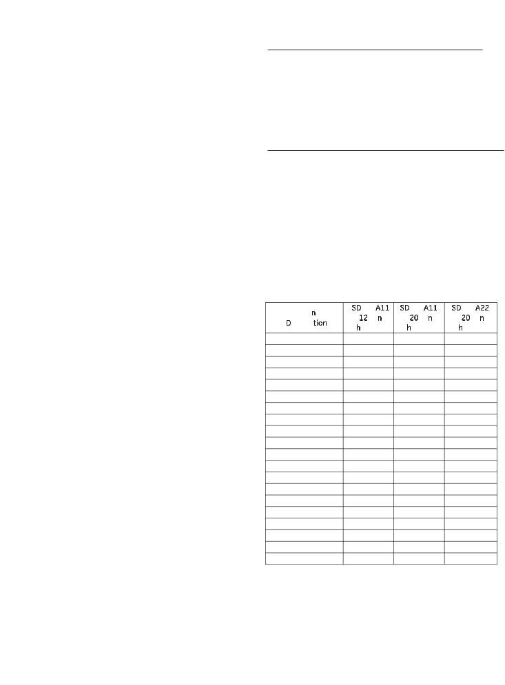
Distribution and Extension Cables Interconnection cables are required if equipment interfaces such as the distribution cable junction box, power supply plate assembly, voltage conditioner plate assembly are used. These cables transmit electronic signals and/or control power between the various interconnected components. There are two different types of interconnection cables available for Spectra microEntelliGuardTM breakers – distribution cables and extension cables.
Distribution cables are used to interconnect the junction box, power supply plate assembly, and voltage conditioner plate assembly. These cables have 12-
Pin connectors and are available in three different lengths. Table 10 shows the different lengths and their associated catalog numbers.
11
Table 10. Distribution Cable Harness Options
Catalog Number |
Length (in) |
Wire Connectors |
|
|
|
SDCHA11 |
11 |
12-Pin |
|
|
|
SDCHA30 |
30 |
12-Pin |
SDCHA60 |
60 |
12-Pin |
|
|
|
Extension cables are used to increase the length of an existing cable. Because the Spectra microEntelliGuardTM breakers come with both 12-Pin and 20-Pin wiring harnesses, there are two different extension cables available.
Table 11. Extension Cable Harness Options
Catalog Number |
Length (in) |
Wire Connectors |
|
|
|
SDCEA30 |
30 |
12-Pin |
|
|
|
SDCEA30C |
30 |
20-Pin |
|
|
|
Voltage exchange cables are available and are necessary for breakers with advanced metering when installed in group-mounted equipment. These cables connect between the breaker and the distribution cable junction box and reverse the voltage signals being input to the breaker (from VAV BVC to VCVBVA). Refer to the Phase Rotation description in the Setup Mode section of this manual.
Table 12. Voltage Exchange Harness Options
Catalog Number |
Length (in) |
Wire Connectors |
|
|
|
SDCAA6 |
6 |
12-Pin |
|
|
|
SDCAA6C |
6 |
20-Pin |
Auxiliary Switches
An auxiliary switch is used to monitor the state of the circuit breaker main contacts. Spectra microEntelliGuardTM breakers with communications are capable of communicating the breaker position when an auxiliary switch is installed and connected via a terminal board or junction box. Note: auxiliary switches with gold plated contacts are required.
Table 13. Auxiliary Switch Options |
|
||
Catalog Number |
No. of Switch Elements Switch Rating |
||
SAUXGAB1 |
1 form C |
Gold-Plated |
|
Contacts |
|||
SAUXGAB2 |
2 form C |
||
0.5 A @ 30 V |
|||
|
|
||

GEH-702 Users Manual
All Spectra circuit breakers use the same auxiliary switches, which are installed in the breaker’s righthand accessory compartment. Group mounted Spectra breakers with an auxiliary switch that connects to a junction box require a 1 “X” filler plate adjacent
to the breaker’s right-hand side to accommodate the auxiliary switch wiring.
Communications
The Spectra microEntelliGuardTM breaker is available with Modbus communications, which allows connection to an external Modbus network and monitoring platform. Connection to the network requires the appropriate terminal board or junction box. Proper operation of the circuit breaker’s protective functions is not dependent on the communications network.
Spectra microEntelliGuardTM breakers are compatible with EnerVista Viewpoint power system software allowing for remote monitoring and control of the breaker. Viewpoint Monitoring automatically detects Spectra microEntelliGuardTM breakers, generates custom tailored monitoring screens, monitors power quantities in real time (current, voltage, VARs, etc.), and identifies the status of protected assets.
Reduced Energy Let-Through
Reduced energy let-through, or RELT, is an advanced protective function that allows the trip unit to have an alternate instantaneous pickup value. This feature is intended to allow the user to set a lower instantaneous pickup level and reduce the amount of breaker let-through energy in the event of a fault. Trip units optioned with the RELT function require either a
terminal board or junction box in order to wire the RELT input and output signals. The RELT switch is enabled via a 24V (AC or DC) signal across the input contacts or via the Modbus communications network. This signal can be derived from the power supply plate assembly or it can be from a separate source. Trip units optioned with the RELT function have dedicated input and output contacts. The output contacts change state when the RELT function is enabled. The output contacts are rated 1 amp, 60 Vac/Vdc. A RELT kit (catalog number GTURSK) is available that provides an illuminated 3-position selector switch allowing the user to select between NORMAL, TEST, and ON positions. A typical wiring diagram for the RELT connections is shown in Figure 3.
Figure 3. Typical RELT Wiring Diagram
Caution: Setting the RELT instantaneous pickup value greater than the standard instantaneous pickup value will result in higher breaker let-through energy in the event of a fault . The factory default setting for RELT instantaneous is 1.5 x sensor rating which is the minimum setting value.
Zone Selective Interlock
Zone Selective Interlocking, or ZSI, is an advanced protective function that allows one ZSI enabled trip unit to communicate with another ZSI enabled trip unit. The microEntelliGuardTM trip unit is available with ZSI signaling on the short time, ground fault, and instantaneous functions. In the event of an overcurrent pickup condition, the downstream ZSI trip unit signals the upstream ZSI trip unit to temporarily change the affected pickup settings to values that allow the downstream trip unit/breaker to respond to
the overcurrent condition (and the upstream breaker to remain closed and continue to service other loads).
Trip units optioned with the ZSI function require either a terminal board or junction box in order to wire the ZSI input and output signals and +24Vdc control power. A ZSI module (catalog number TIM1) is available that allows multiple ZSI enabled trip units to communicate with one another for optimal system selectivity.
12

GEH-702 Users Manual
Figure 4. Typical microEntelliGuardTM System
13

GEH-702 Users Manual
Section 2 microEntelliGuardTM Trip Unit
Overview
The microEntelliGuardTM Trip Unit is the latest and most advanced trip unit available in the Spectra line of molded case circuit breakers. The trip unit design is based on the EntelliGuardTM Trip Unit platform. Unlike the EntelliGuardTM Trip Unit (which is removable), the microEntelliGuardTM Trip Unit is integral to the Spectra G & K frame circuit breakers. The next sections of this instruction review the trip unit’s HMI (Human Machine Interface), power requirements, operating modes, and communications. If you are familiar with the EntelliGuardTM Trip Unit, then many of the following sections will be familiar to you.
LED
Figure 5. LED Location
HMI
The microEntelliGuardTM HMI consists of a five-button membrane keypad, a liquid crystal display (LCD), and an LED indicator.
The membrane keypad has five pushbuttons that are used to navigate between the various operating modes and set up screens. The pushbuttons are raised, which helps with programming in low-light conditions. The effects of each pushbutton are shown in the following figure.
Up Scroll up or increment value
↓Down Scroll down or decrement value
→Right Next function or next page
←Left Previous function or previous page
Enter Save or set into memory
Figure 6. Keypad Definition
Pushing and holding the UP and DOWN buttons causes the displayed value to continuously increment or decrement. The RIGHT, LEFT, and ENTER buttons operate with individual keystrokes. Pressing and holding the LEFT button causes the trip unit to return to the “home” screen.
Figure 7. Typical LCD Screen
It is important to note that any programmable value that is changed is NOT saved until the ENTER key
is pushed and that the ENTER key is pushed before proceeding to the next or previous programming screen. Advancing to the next screen or returning to a previous screen without hitting the ENTER key causes any changes to be lost.
Liquid Crystal Display and Power Requirements
The LCD is the visual interface that displays the operating modes and setup screens of the trip unit. Input power is required in order to illuminate the microEntelliGuardTM Trip Unit’s LCD for viewing the display screens or making changes to setup values. Any of the following power sources can be used.
Load Current – the trip unit will “self power” and illuminate the LCD when sufficient current passes through the circuit breaker. Sufficient current is defined as 20% of the breaker’s sensor rating. A breaker
with 150 amp sensors requires at least 30 amps to illuminate the LCD.
24 Vdc Control Power – microEntelliGuardTM Trip Units with 12-Pin and 20-Pin wiring harnesses can be connected to 24 Vdc control power via a terminal board connection or a junction box to illuminate the LCD.
14

GEH-702 Users Manual
Digital Test Kit – the EntelliGuard test kit (catalog number GTUTK20) connects to the microEntelliGuardTM DB-15 connector and provides 24 Vdc power to illuminate the LCD.
Portable Battery Pack – the Spectra portable battery pack (catalog number TVPBP) in conjunction with an adapter cable (TVPBPACC) connects to the microEntelliGuardTM DB-15 connector and provides 24 Vdc power to illuminate the LCD.
LED Status Indicator
The microEntelliGuardTM HMI includes a green LED status indicator, which signals the status of the trip unit/breaker. There are four different status conditions. NORMAL status means the breaker and trip unit are functioning properly and that the trip unit is NOT in a pickup condition. PICKUP status means that one of the over-current protective functions or protective relays has gone into pickup and that a trip is imminent. TRIP status means that the breaker/trip unit has tripped due to an over-current protective function, protective relay, or trip unit error. ERROR status can mean any number of conditions (for example, the rating plug is missing or an improper rating plug is installed). In the event that the LED sequence indicates an ERROR, check the error code in the trip unit’s status menu. To reset the LED pattern, once the issue is corrected, hold down the right arrow key for two seconds.
Table 14. LED Status Flash Sequence
Breaker/Trip Unit Status |
LED Sequence |
NORMAL |
ON-OFF-ON-OFF (wait for 2 sec) |
PICKUP |
ON-OFF-ON-OFF (continuous) |
TRIP |
ON-OFF (wait 2 sec) |
ERROR |
ON-OFF-ON-OFF-ON-OFF (wait 2 sec) |
Trip Unit Operating Modes
The microEntelliGuardTM trip unit has four different operating modes. They are SETUP, METERING, STATUS, and EVENTS. The SETUP mode is used to make changes to all of the adjustable parameters optioned in the trip unit. The METERING mode displays the current in each phase of the breaker. Trip units that are optioned with advanced metering can display voltage, power, and other pertinent parameters associated with the system voltage. The STATUS mode displays pertinent information on trip unit protection settings, if the trip unit is in pickup mode, the position of the breaker’s main contacts (requires installation of
15
auxiliary switch) and communications settings. The EVENTS mode displays information regarding overcurrent events.
Setup Mode
The following instructions describe setup procedures for all of the available trip unit functions. All microEntelliGuardTM Trip Units have adjustable long time, short time and instantaneous over-current protection options as well as a selectable ammeter. All other functions are optional and depend on how the trip unit is optioned. If a specific trip unit function has not been optioned, that function will not appear in the display. Setting for the over current protective parameters (long time, short time, instantaneous, and ground fault) establish the shape of the trip unit/ breaker’s time current curve. All optioned trip unit parameters are factory preset values (reference appendix A for factory preset values).
Prior to setting up the trip unit, ensure that
•An appropriate rating plug is installed (the trip unit automatically checks and records the value of the installed rating plug and will issue an error if the rating plug is not appropriate or missing).
•A professional engineer has performed a system coordination study and provided the appropriate setup values to be programmed into the trip unit (inappropriate setup values can cause the breaker to trip unexpectedly or not provide the intended circuit protection).
•The LCD is illuminated via an appropriate power source.
When the LCD is first illuminated, the “home” page displays SETUP, METERING, STATUS, EVENTS. Use the buttons on the keypad to move up and down the menu. When STATUS is highlighted, push the right button to get into the SETUP screens. Use the RIGHT and LEFT buttons to move to the various setup options. Use the UP and DOWN buttons to change parameter values. Any value that is changed using the UP or DOWN buttons will flash to indicate that a change has been made. Note: values that are changed must be saved to memory on the screen in which they were changed. Press and hold the ENTER button to save changes. Failure to save setting changes before proceeding
to the next screen causes the setting to return to its previous setting. Always confirm trip unit settings after making changes by exiting and re-entering the SETUP mode and rechecking each setting.
 Loading...