


 Loading...
Installation Guide for Galaxy Power Systems
Note: Instructions in this manual reference installation and setup of GPS systems with Galaxy Millennium Controllers and 596 or 596 rectifiers. For installation and setup with other controllers and rectifiers refer to
these product manuals. |
|
GalaxyMillennium II Product Manual |
167-792-181 |
GalaxyPulsar Plus Product Manual |
CC848815341 |
NE Rectifiers |
|
GPS2436 Product Manual |
850022020 |
GPS4827 Product Manual |
850022019 |
Installation Guide
Select Code 167-792-157
Comcode 108327362
Issue 12
August 2012
Installation Guide
Select Code 167-792-157
Comcode 108327362
Issue 12
August 2012
Installation Guide for Galaxy Power Systems
Notice:
The information, specifications, and procedures in this manual are subject to change without notice. Lineage Power assumes no responsibility for any errors that may appear in this document.
© 2011 Lineage Power
All International Rights Reserved
Printed in U.S.A.

Installation Guide for Galaxy Power Systems
Table of Contents
1 |
Introduction |
|
|
Product Documentation |
1-1 |
|
This Installation Guide |
1-1 |
|
Revisions |
1-1 |
|
Related Documentation |
1-1 |
|
Customer Service Contacts |
1-3 |
|
Customer Service, Technical Support, Product Repair and Return, |
|
|
and Warranty Service |
1-3 |
|
Customer Training |
1-3 |
|
Downloads and Software |
1-3 |
2 Safety |
|
Safety Statements |
2-1 |
Warning and Safety Symbols |
2-3 |
Precautions |
2-4 |
Special Installation Notes |
2-9 |
Deutsch - German |
2-9 |
Español - Spanish |
2-11 |
3 Getting Started
Tools and Hardware |
3-1 |
Torque Settings for Hardware |
3-3 |
Unpacking |
3-4 |
Location |
3-4 |
4 System Electrical Architecture Overview
Introduction |
4-1 |
Bonding Network |
4-1 |
Facility |
4-1 |
Single Cabinet System |
4-2 |
Distributed Architecture |
4-3 |
Centralized Architecture |
4-6 |
5 Cabinet Floor Mounting and Battery Stand
Connection
Cabinet Installation |
5-2 |
Mounting Plates for Unigy Batteries |
5-13 |
Mounting Specifications |
5-14 |
Procedure |
5-15 |
Cabinet Ground and Central Office Ground |
5-17 |
|
5-17 |
Issue 12 August 2012 |
Table of Contents - 1 |

Installation Guide for Galaxy Power Systems
Cabinet Ground Procedure |
5-17 |
Central Office Ground Procedure |
5-17 |
Recommended Cable Rack Layout |
5-20 |
6 Centralized or Distributed Architecture Connections
|
Multiple-Cabinet Installations |
6-1 |
|
Special Requirements |
6-1 |
|
Centralized Architecture |
6-2 |
|
DC Power Connections to Central Bus Bar |
6-2 |
|
Remote Voltage Sense and System Shunt |
|
|
for Galaxy Millennium Controller |
6-4 |
|
Remote Voltage Sense and System Shunt |
|
|
for Galaxy Vector Controller |
6-6 |
|
Distributed Architecture |
6-8 |
|
Intercabinet DC Power Bus Connections |
6-8 |
|
Intercabinet Alarm and Serial Bus Connections |
6-10 |
|
BLJ2/3 to BLJ2/3 (Millennium Controller) |
6-10 |
|
BLJ3 to BLJ3 (Vector Controller) |
6-12 |
7 |
AC Connection and Wiring |
|
|
Safety |
7-1 |
|
Reference Information |
7-1 |
|
Wire Sizing and Ampacity |
7-2 |
|
AC Input Schemes |
7-3 |
|
595 Rectifiers (48V, 200A) and 595LT Rectifiers (48V, 220A) |
7-3 |
|
596 Rectifiers (24V, 100A/125A and 48V, 50A/100A) |
7-3 |
|
AC Cable Routing |
7-4 |
|
Rectifier Positions |
7-6 |
|
AC Input Panels Cross Reference |
7-8 |
|
AC Input Panels |
7-10 |
|
|
7-26 |
Field Modification of the 1-Phase Circuit Breaker AC Panel for use with Phase-Neutral Input Circuits - ED83142-30 G-6, G7, G19, G21, or
G23 |
7-27 |
Bottom Cable Feed Options for GPS 4848/100 |
7-28 |
Completing the AC Connection |
7-29 |
8 DC Distribution Assembly and Connections
Overview |
8-1 |
DC Distribution Panels Cross Reference |
8-2 |
Connecting Loads |
8-3 |
Cable Routing Strategy |
8-3 |
Capacitor Charge Unit |
8-3 |
Mounting Large Circuit Breakers |
8-4 |
2 - Table of Contents |
Issue 12 August 2012 |

|
Installation Guide for Galaxy Power Systems |
|
|
Mounting Small Plug-in Circuit Breakers and Fuses |
8-4 |
|
Disrtibution Panels |
8-5 |
|
Low Voltage Disconnect Feature |
8-20 |
|
EBV Circuit Pack |
8-20 |
9 |
Converters |
|
|
Introduction |
9-1 |
|
Installing the Converter Carrier |
9-2 |
|
Setting the CIC ID |
9-4 |
|
Converter Wiring |
9-5 |
10 |
Remote Peripheral Monitoring |
|
|
Overview |
10-1 |
|
RPM Modules |
10-1 |
|
Current Limiting Resistors |
10-2 |
|
Mounting Locations |
10-2 |
|
RPM Installation |
10-3 |
11 |
Battery Connection Panels |
|
|
Connecting and Disconnecting Batteries |
11-1 |
|
Battery Connection Panels Cross Reference |
11-2 |
|
Additional Battery Leads |
11-3 |
|
Battery Connection Panel Options |
11-4 |
|
Connecting (+) and (-) Conductors |
11-7 |
|
+24-volt Systems |
11-7 |
|
-48-volt Systems |
11-7 |
|
Installing Battery Connection Panels |
11-8 |
|
Contactor Control Board |
11-9 |
|
Full-Height Cabinet |
11-9 |
|
Half-Height Cabinet |
11-10 |
|
Battery and Alarm Fuses and Circuit Breakers |
11-11 |
12 |
Thermal Probe and 210E Connections |
|
|
Introduction |
12-1 |
|
Cable Letter Codes |
12-2 |
|
Connecting Thermal Probe Cable Assembly |
12-3 |
|
Millennium Controller |
12-3 |
|
Vector Controller |
12-4 |
|
Wiring Schematic for Extender Cable |
12-5 |
|
Cable Routing |
12-5 |
|
Connecting Thermal Probe Assembly |
12-6 |
|
BLJ Board |
12-6 |
|
Millennium Controller |
12-7 |
|
Connecting a 210E Module to the Controller or BLJ Board |
12-8 |
|
Connecting Cable Assembly to the 210E |
12-11 |
Issue 12 August 2012 |
Table of Contents - 3 |

Installation Guide for Galaxy Power Systems
Connecting Cable Assembly to Thermal Probes |
12-12 |
Monitoring a 210E Alarm Signal, BLJ-BIC7/8 with Millennium |
12-13 |
13 Fascia Cover Installation
Introduction |
13-1 |
Installing the Fascia Covers |
13-2 |
14 Connection of Office Alarms
Introduction |
14-1 |
Connecting Controller Alarms |
14-1 |
15 Power Up and Installation Completion
Initial System Checkout and Preparation for Power Up |
15-1 |
Controller Front Panels |
15-1 |
Millennium |
15-2 |
Vector |
15-3 |
Initial Power Up of the System |
15-4 |
Rectifier Installation Notes |
15-4 |
Install First Rectifier |
15-5 |
Install Converter Cards |
15-6 |
Verify Controller |
15-6 |
Set Rectifier ID |
15-7 |
Installing Rectifiers and Converters |
15-9 |
Lamp Test |
15-11 |
Voltage Calibration |
15-12 |
Setting the System Float Voltage |
15-13 |
Setting the System Shunt |
15-14 |
Setting the Low-Voltage Battery Disconnect Feature |
15-15 |
Setting the Low-Voltage Load Disconnect Feature |
15-17 |
Connecting Batteries |
15-19 |
Testing Rectifiers and Load Share |
15-21 |
Testing Temperature Compensation (Optional Feature) |
15-22 |
Testing Additional Alarms |
15-23 |
Testing the BD Alarm and High Voltage Shutdown |
15-24 |
Galaxy Millennium Controller System Alarm Test |
15-25 |
Connecting to Load |
15-25 |
16 Addition or Modification to a Galaxy Power System
Upgrading a GPS4848 System to a GPS4848/100 System |
16-1 |
Adding an ED83143-31 Distribution Panel to a GPS |
16-2 |
Installing an LVLD Contactor (if required) |
16-5 |
Adding a Cabinet to an Existing GPS System with |
|
Distributed Architecture. |
16-6 |
4 - Table of Contents |
Issue 12 August 2012 |

Installation Guide for Galaxy Power Systems
Replacing the Bay Interface Card (BIC) or BLJ3 |
|
Terminal Board |
16-7 |
Issue 12 August 2012 |
Table of Contents - 5 |

Installation Guide for Galaxy Power Systems
6 - Table of Contents |
Issue 12 August 2012 |
Installation Guide for Galaxy Power Systems
List of Figures
Figure 2-1: Short Circuit Current Calculations |
2-5 |
Figure 4-1: Single-Cabinet Configurations |
4-2 |
Figure 4-2: Two-Cabinet Configuration, |
|
Distributed Architecture |
4-4 |
Figure 4-3: Three-Cabinet (or more) Configuration, |
|
Distributed Architecture |
4-5 |
Figure 4-4: Centralized Architecture |
4-6 |
Figure 5-1: Footprint for Galaxy Power System Cabinets |
|
(without a Battery Stand) |
5-2 |
Figure 5-2: Footprint for a European Battery Stand |
5-3 |
Figure 5-3: Half-Height Cabinet on a European Battery Stand |
5-4 |
Figure 5-4: Footprint for a 12IR125/12IR125LP (Low Profile) |
|
Battery Stand |
5-5 |
Figure 5-5: Half-Height Cabinet on a 12IR125 Battery Stand |
5-6 |
Figure 5-6: Half-Height Cabinet on a 12IR125LP |
|
(Low Profile) Battery Stand |
5-7 |
Figure 5-7: Footprint for a 2VR375 Battery Stand |
5-8 |
Figure 5-8: Half-Height Cabinet on a 2VR375 Battery Stand |
5-9 |
Figure 5-9: Footprint for a 2VR250 Battery Stand |
5-10 |
Figure 5-10: Half-Height Cabinet on a 2VR250 Battery Stand |
5-11 |
Figure 5-11: Half-Height Cabinet on a Unigy Battery |
|
Module Assembly |
5-12 |
Figure 5-12: Cabinet Installation Procedure |
5-16 |
Figure 5-13: Full-Height Cabinet and System Central Office |
|
Ground |
5-18 |
Figure 5-14: Half-Height Cabinet and System Central Office |
|
Ground |
5-19 |
Issue 12 August 2012 |
List of Figures - 1 |

Installation Guide for Galaxy Power Systems
Figure 5-15: Various Cable Rack Arrangements |
5-20 |
Figure 6-1: DC Power Connections to Centralized Bus Bars |
6-3 |
Figure 6-2: System Shunt and Remote Voltage Sense |
|
for Galaxy Millennium Controller |
6-5 |
Figure 6-3: System Shunt and Remote Voltage Sense |
|
for Galaxy Vector Controller |
6-7 |
Figure 6-4: Distributed Architecture Intercabinet DC Power |
|
Bus Connections (Full-Height Cabinets Only) |
6-9 |
Figure 6-5: BLJ2 or BLJ3 Board Connections, |
|
Millennium Controller |
6-10 |
Figure 6-6: BLJ2/3 DIP Switch Settings When Using a |
|
Millennium Controller |
6-11 |
Figure 6-7: BLJ3 to BLJ3 Board Connections, |
|
Vector Controller |
6-13 |
Figure 6-8: BLJ3 DIP Switch Settings When Using a |
|
VectorController |
6-15 |
Figure 7-1: Attaching AC Conduit |
7-5 |
Figure 7-2: 595 and 596 Series Rectifier Positions |
7-6 |
Figure 7-3: Dual Shelf Rectifier Positions |
7-7 |
Figure 7-4: ED83142-30 Group 2 (H569-434 G22, G322) |
|
AC Input Panel for 595A or LTA Series Rectifiers |
7-10 |
Figure 7-5: ED83142-30 Group 3 (H569-434 G20, G220, G320) |
|
AC Input Panel for 595B, LTB, or C (DA) Series Rectifiers |
7-11 |
Figure 7-6: ED83142-30 Group 4 (H569-434 G21, G23, G321, G323, G421)
AC Input Panel for 595A, B, LTA, LTB, or C (DA) Series Rectifiers 7-12
Figure 7-7: ED83142-30 Group 24 or 25 (H569-434 G334, G335)
AC Input Panel for 595LTA or LTB Series Rectifiers |
7-13 |
Figure 7-8: ED83142-30 Group 5
(H569-434 G24, G25, G26, G27, G224, G226, G324, G325, G326,
G327, G425, G429) |
|
AC Input Panel for 595A, B, or C (DA) Series Rectifiers |
7-14 |
2 - List of Figures |
Issue 12 August 2012 |

Installation Guide for Galaxy Power Systems
Figure 7-9: ED83142-30 Groups 6/6M |
|
|
(H569-436/H569-437 G71H, G73F, G74H, G74F) |
|
|
AC Input Panel for |
596A or B Series Rectifiers |
7-15 |
Figure 7-10: ED83142-30 Group 7 (H569/436/H569-437 G72F) |
|
|
AC Input Panel for |
596A Series or 596B Series Rectifiers |
7-16 |
Figure 7-11: ED83142-30 Group 8 or 9
(H569-436 G76H, G77F, G78F, G79F; H569-437 G76H, G77F,
G78F) |
|
AC Input Panel for 596A Series or 596B Series Rectifiers |
7-17 |
Figure 7-12: Wire Termination for ED83142-30 G-8, G9, G20, G22 (H569-436 G76H, G77F, G78F, G79F, G175H, G176H, G177F,
G178F, G179F; |
|
H569-437 G76H, G77F, G78F) |
7-18 |
Figure 7-13: ED83142-30 Group 10 (H569-434 G70, G270, G370) |
|
AC Input Panel for 595A Series Rectifiers |
7-19 |
Figure 7-14: ED83142-30 Group 11 (H569-434 G71, G371, G471) |
|
AC Input Panel for 595A Series Rectifiers |
7-20 |
Figure 7-15: ED83142-30 Group 18 (H569-434 G128, G129, G130, |
|
G131, G224, G226, G330, G331) |
|
AC Input Panel for 595A or 595B Series Rectifiers |
7-21 |
Figure 7-16: ED83142-30 Group 26 (H569-434 G328, G329, G332, |
|
G333) |
|
AC Input Panel for 595LTA or 595LTB Series Rectifiers |
7-22 |
Figure 7-17: ED83142-30 Group 19 (H569-436 G172F) |
|
AC Input Panel for 596D Series Rectifiers |
7-23 |
Figure 7-18: ED83142-30 Group 20, 22 (H569-436 G175H, G176H, |
|
G177F, G178F, G179F) |
|
AC Input Panel for 596D Series Rectifiers |
7-24 |
Figure 7-19: ED83142-30 Group 21 (H569-436 G171H) |
|
AC Input Panel for 596D series Rectifiers |
7-25 |
Figure 7-20: ED83142-30 Group 23 (H569-436 G173F) |
|
AC Input Panel for 596D Series Rectifiers |
7-26 |
Figure 7-21: Neutral AC Input for ED83142-30 G6, G7, G19, G21 or
G23 H569-436 G71H, G72F, G73F, G171H, G172F, G173F; |
|
H569-437 G71H, 72F, or G73F |
7-27 |
Figure 7-22: Bottom Cable Feed Option for GPS4848/100 |
7-28 |
Issue 12 August 2012 |
List of Figures - 3 |

Installation Guide for Galaxy Power Systems
Figure 8-1: Installation of Large Circuit Breakers |
|
||
and Capacitor Charge Unit |
|
8-3 |
|
Figure 8-2: ED83143-31 Group 1 DC Distribution Panel |
8-5 |
||
Figure 8-3: ED83143-31 Group 2 DC Distribution Panel |
8-6 |
||
Figure 8-4: ED83143-31 Group 5 DC Distribution Panel |
8-7 |
||
Figure 8-5: ED83143-31 Group 11 |
DC Distribution Panel |
8-8 |
|
Figure 8-6: ED83143-31 |
Group 12 |
DC Distribution Panel |
8-9 |
Figure 8-7: ED83143-31 |
Group 15 |
DC Distribution Panel |
8-10 |
Figure 8-8: ED83143-31 |
Group 16 |
(14 position) and |
|
Group 17 (22 position) DC Distribution Panels |
8-11 |
||
Figure 8-9: ED83143-31 |
Group 21 |
DC Distribution Panel |
8-12 |
Figure 8-10: ED83143-31 Group 22 DC Distribution Panel |
8-13 |
||
Figure 8-11: ED83143-31 Group 53 DC Distribution Panel |
8-14 |
||
Figure 8-12: ED83143-31 Group 54 (5 position) DC Distribution Panel
8-15 |
|
Figure 8-13: ED83143-31 Group 55 DC Distribution Panel |
8-16 |
Figure 8-14: ED83143-31 Group 56 DC Distribution Panel |
8-17 |
Figure 8-15: ED83143-31 Group 58 (6 positionGMT) DC Distribution
Panel |
8-18 |
Figure 8-16: ED83143-31 Groups 71 and 171 |
|
DC Distribution Panel |
8-19 |
Figure 8-17: EBV Circuit Pack for Load Disconnect |
8-20 |
Figure 9-1: Converter Position |
9-3 |
Figure 9-2: Installing a Second Carrier |
9-3 |
Figure 9-3: Setting the CIC ID Switch |
9-4 |
Figure 9-4: Converter Connection for System Ground |
9-6 |
Figure 9-5: Connection Point for System Ground Wire |
9-7 |
Figure 9-6: Installation of Load Circuit Breakers into 597A |
|
Converter Carrier |
9-8 |
Figure 10-1: Possible RPM Mounting Locations |
10-2 |
4 - List of Figures |
Issue 12 August 2012 |

Installation Guide for Galaxy Power Systems
Figure 10-2: Connection of Voltage, Shunt, Transducer, |
|
and Binary Modules |
10-5 |
Figure 10-3: Connection of Temperature Module |
10-6 |
Figure 10-4: Connection of Control Relay Module |
10-7 |
Figure 10-5: Connection to the Controller (All Modules) |
10-8 |
Figure 10-6: RPM Module Assembly |
10-9 |
Figure 11-1: Additional Battery Leads |
11-3 |
Figure 11-2: H569-434 Battery Connection Panel Options |
11-4 |
Figure 11-3: H569-436 Battery Connection Panel Options |
11-5 |
Figure 11-4: H569-437 Battery Connection Panel Options |
11-6 |
Figure 11-5: BJN Low Voltage Battery Disconnect |
|
Contactor Control Board (Full-Height Cabinet) |
11-9 |
Figure 11-6: BJN Low Voltage Battery Disconnect |
|
Contactor Control Board (Half-Height Cabinet) |
11-10 |
Figure 12-1: Thermal Probe Cable Assembly Connection |
|
to Millennium Controller |
12-3 |
Figure 12-2: Thermal Probe Cable Assembly Connection |
|
to Vector Controller |
12-4 |
Figure 12-3: Wiring Schematic for Extender Cable |
12-5 |
Figure 12-4: Thermal Probe and 210E Cable Routing |
12-5 |
Figure 12-5: Thermal Probe Connection to BLJ Board |
12-6 |
Figure 12-6: Thermal Probe Connection to Millennium |
|
Controller |
12-7 |
Figure 12-7: 210E Connection to Vector Controller or BLJ |
12-9 |
Figure 12-8: 210E Connection to the Millennium Controller |
12-10 |
Figure 12-9: Cable Assembly Connection to 210E |
12-11 |
Figure 12-10: Cable Assembly Connection to Thermal Probes |
12-12 |
Figure 12-11: Monitoring a 210E Alarm off the BLJ-BIC7/8 in a |
|
Millennium System |
12-13 |
Figure 13-1: Fascia Cover Installation |
13-2 |
Issue 12 August 2012 |
List of Figures - 5 |

Installation Guide for Galaxy Power Systems
Figure 14-1: Galaxy Millennium Controller |
|
with Insulation Displacement Alarm Board |
14-2 |
Figure 14-2: Galaxy Millennium Controller |
|
with Wire Wrap Alarm Board |
14-3 |
Figure 14-3: Galaxy Vector Controller With Insulation |
|
Displacement Alarm Board |
14-4 |
Figure 15-1a: Galaxy Millennium Controller Front Panel , Square Keys |
|
(DA) |
15-2 |
Figure 15-1b: Galaxy Millennium Controller Front Panel, Round Keys
15-2
Figure 15-2a: Galaxy Vector Controller Front Panel, Square Keys (DA) 15-3
Figure 15-2b: Galaxy Vector Controller Front Panel, Round Keys
15-3
Figure 15-3: Installing 595A/B Rectifiers, 596 Rectifiers, and 597A
Converter Carriers |
15-9 |
Figure 15-4: Installing 595LTA and 595LTB Rectifiers |
15-10 |
Figure 15-5: Battery Connection Panel |
15-20 |
Figure 16-1: Adding an ED83143-31 Distribution Panel to GPS |
16-3 |
Figure 16-2: Adding an LVLD to a Distribution Panel |
16-5 |
Figure 16-3: BLJ3 Terminal Board |
16-7 |
Figure 16-4: BIC/BLJ3 Mounting on a GPS |
16-8 |
6 - List of Figures |
Issue 12 August 2012 |

Installation Guide for Galaxy Power Systems
List of Tables
Table 2-A: Cable Run Lengths |
2-6 |
Table 2-B: Interrupt Current Ratings for Fuses |
|
and Circuit Breakers |
2-7 |
Table 3-A: Torque Settings for Hardware |
3-3 |
Table 5-A: Mounting Plates for Unigy Batteries |
5-13 |
Table 5-B: GPS Mounting Specifications |
5-14 |
Table 7-A: Wire Sizing and Ampacity |
7-2 |
Table 7-B1: AC Panels Cross Reference - GPS4848/100 |
7-8 |
Table 7-B2: AC Panels Cross Reference - GPS4812/24 and GPS2424/ |
|
30 (208/240Vac) |
7-9 |
Table 8-A: DC Distribution Panels Cross Reference |
8-2 |
Table 10-A: RPM Modules and Connection Units |
10-1 |
Table 11-A: Battery Connection Panels Cross Reference |
11-2 |
Table 12-A: Cable Letter Codes |
12-2 |
Issue 12 August 2012 |
List of Tables - 1 |

Installation Guide for Galaxy Power Systems
1 Introduction
Product Documentation
This Installation
Guide
This Installation Guide provides instructions for installing Lineage Power Galaxy Power Systems that use 595A or 595B series (-48V/200A), 595LTA or 595LTB series (-48V/220A), 596A series (-48V/50A), 596B series (+24V/100A or 125A), or 596D series (-48V/100A) rectifiers.
Revisions |
For information on systems components that are no longer available |
|
(Discontinued Availibility DA) see earlier issues of this manual: |
|
Galaxy RC or SCF Controllers - see Issue 5 |
|
Plastic Door - see Issue 8 |
|
595C Rectifier - see Issue 8 |
Related
Documentation
|
GPS2424/30 |
|
|
|
|
Ordering Guide |
|
H569-437 |
Manufacturing Drawings |
|
ED83142-30 (AC) |
|
|
ED83143-31 (DC) |
|
|
J85582E-1 (System) |
Wiring Diagram |
|
T83314-30 |
User’s Guide |
|
167-792-159 |
|
GPS4812/24 |
|
|
|
|
Ordering Guide |
|
H569-436 |
Manufacturing Drawings |
|
ED83142-30 (AC) |
|
|
ED83143-31 (DC) |
|
|
J85582E-1 (System) |
Wiring Diagram |
|
T83314-30 |
User’s Guide |
|
167-792-161 |
|
GPS4848/100 |
|
|
|
|
Ordering Guide |
|
H569-434 |
Manufacturing Drawings |
|
ED83142-30 (AC) |
|
|
ED83143-31 (DC) |
|
|
J85582C-1 (System) |
Wiring Diagram |
|
T83314-30 |
User’s Guide |
|
167-792-155 |
Issue 12 August 2012 |
Introduction 1 - 1 |
Installation Guide for Galaxy Power Systems
Product Documentation, continued
Related Product |
Galaxy Millennium Controller |
||
Manuals, |
|||
continued |
|
|
|
Manufacturing Drawing |
J85501K-1 |
||
|
|||
|
Wiring Diagram |
T83413-30 |
|
|
Product Manual |
167-792-180 |
|
Galaxy Vector Controller
Wiring Diagram |
T83314-30 |
Product Manual (BIC2, BIC3) |
167-792-112 |
Product Manual (GCM2, GCM3) |
167-792-115 |
Remote Peripheral Monitoring System
Manufacturing Drawing |
J85501G-1 |
Wiring Diagram |
T83275-30 |
Schematic Drawing |
SD-83275-01 |
Product Manual Select Code |
167-790-063 |
|
EasyView Software |
|
|
|
|
Product Manual |
|
193-104-105 |
Galaxy Gateway Card (Internet) |
||
|
|
|
Product Manual |
|
193-104-106 |
1 - 2 Introduction |
Issue 12 August 2012 |
Installation Guide for Galaxy Power Systems
Customer Service Contacts
Customer Service,
Technical Support,
Product Repair and
Return, and
Warranty Service
Customer Training
Downloads and
Software
For customers in the United States, Canada, Puerto Rico, and the US Virgin Islands, call 1-800-THE-1PWR (1-800-843-1797). This number is staffed from 7:00 am to 5:00 pm Central Time (zone 6), Monday through Friday, on normal business days. At other times this number is still available, but for emergencies only. Services provided through this contact include initiating the spare parts procurement process, ordering documents, product warranty administration, and providing other product and service information.
For other customers worldwide the 800 number may be accessed after first dialing the AT&T Direct country code for the country where the call is originating, or you may contact your local field support center or your sales representative to discuss your specific needs.
Lineage Power offers customer training on many Power Systems products. For information call 1-972-284-2163. This number is answered from 8:00 a.m. until 4:30 p.m., Central Time Zone (Zone 6), Monday through Friday.
To download the latest product information, product software and software upgrades, visit our web site at http://www.lineagepower.com
Issue 12 August 2012 |
Introduction 1 - 3 |

Installation Guide for Galaxy Power Systems
1 - 4 Introduction |
Issue 12 August 2012 |

Installation Guide for Galaxy Power Systems
1 - 6 Introduction |
Issue 12 August 2012 |

Installation Guide for Galaxy Power Systems
2 Safety
Safety Statements
Please read and follow all safety instructions and warnings before installing, maintaining, or repairing a Galaxy Power System. Reference the individual module product manuals for additional safety statements specific to the modules.
•The Galaxy Power System is Underwriters Laboratories (UL) Listed per Subject Letter 1801, DC Power Distribution Centers for Telecommunications Equipment, and VDE Licensed to EN60950 (H569-436 and H569-437 only). Rectifiers are individually UL Recognized and/or CSA Certified to UL1950 and CSA C22.2 No. 234/950. Rectifiers are also approved to IEC-950/EN60950 by an EC Notified Body and have outputs classified as SELV.
•Install only in restricted access areas (dedicated equipment rooms, equipment closets, or the like) in accordance with articles 110-16, 110-17, and 110-18 of the U.S. National Electric Code (NEC), ANSI/NFPA No. 70, and pursuant to applicable local codes.
•Use this equipment in a controlled environment (an area where the humidity is maintained at levels that cannot cause condensation on the equipment, the contaminating dust is controlled, and the steady-state ambient temperature is within the range specified). GPS4848/100 has been evaluated for use in a continuous ambient temperature not to exceed 40°C. Short-term excursions to 45°C are acceptable. GPS4848/100 with Dual Rectifier Shelf has been evaluated for use in a continuous ambient temperature not to exceed 40°C. Short-term excursions to 50°C are acceptable. GPS2424/30 and GPS4812/24 have been evaluated for use in a continuous ambient temperature not to exceed 45°C. Short-term excursions to 50°C are acceptable.
•Do not install this equipment over combustible surfaces.
Issue 12 August 2012 |
Safety 2 - 1 |

Installation Guide for Galaxy Power Systems
Safety Statements, continued
•Fuses/circuit breakers may not be provided with the equipment. Refer to the Galaxy Power System documentation for the proper hardware. Use only the parts specified in the Galaxy Power System (GPS) documentation. Installing fuses or circuit breakers not specified for use in this equipment may result in injury to service personnel or equipment damage.
•For installations in the U. S. or Canada, use Listed/Certified compression connectors to terminate Listed/Certified field-wire conductors where required. For all installations, apply the appropriate connector to the correct size conductor as specified by the connector manufacturer, using only the connector manufacturer’s recommended tooling or tooling approved for that connector. If the proper connector for the country of installation is not provided, obtain appropriate connectors and follow manufacturer’s and all local requirements for proper connections. Follow all national and local rules and regulations when making field connections.
•Torque electrical connections to the values specified on labels or in the product documentation.
•Battery input cables must be dressed to avoid damage to the conductors (caused by routing around sharp edges or routing in areas where wires could get pinched) and undue stress on the connectors.
•Either external fuses or external circuit breakers must be sized as required by the National Electric Code (NEC) and/or local codes. Refer to the equipment ratings to assure rating of equipment will not exceed 80% of the value of the protector chosen. Refer to the system T-drawing (wiring diagram) for recommended circuit protection for the different options.
•The ac input distribution has been evaluated for connection of minimum 90°C conductors sized according to the US National Electrical Code using the 90°C ampacity tables. Torque electrical connections to the values specified on labels or in the product documentation.
•Provide an accessible ac disconnect/protection device to remove ac power from the equipment in the event of an emergency. This device must open all poles and be connected together. When connecting to 3-wire plus neutral supply systems, the neutral must be readily earthed at the supply, i.e., this equipment is not intended to be connected to IT supply systems.
2 - 2 Safety |
Issue 12 August 2012 |
Installation Guide for Galaxy Power Systems
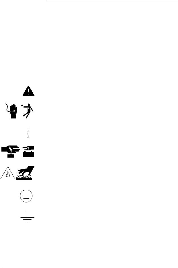
Warning and Safety Symbols
The symbols may sometimes be accompanied by some type of statement; e.g., “Hazardous voltage/energy inside. Risk of injury. This unit must be accessed only by qualified personnel.” Signal words as described below may also be used to indicate the level of hazard
DANGER
WARNING
CAUTION
Indicates the presence of a hazard that will cause death or severe personal injury if the hazard is not avoided.
Indicates the presence of a hazard that can cause death or severe personal injury if the hazard is not avoided.
Indicates the presence of a hazard that will or can cause minor personal injury or property damage if the hazard is not avoided.
This symbol identifies the need to refer to the equipment instructions for important information.
These symbols (or equivalent) are used to identify the presence of hazardous ac mains voltage.
This symbol is used to identify the presence of hazardous ac or dc voltages. It may also be used to warn of hazardous energy levels.
One of these two symbols (or equivalent) may be used to identify the presence of rectifier and battery voltages. The symbol may sometimes be accompanied by some type of statement, for example: “Battery voltage present. Risk of injury due to high current. Avoid contacting conductors with uninsulated metal objects. Follow safety precautions.”
One of these two symbols may be used to identify the presence of a hot surface. It may also be accompanied by a statement explaining the hazard. A symbol like this with a lightning bolt through the hand also means that the part is or could be at hazardous voltage levels.
This symbol is used to identify the protective safety earth ground for the equipment.
This symbol is used to identify other bonding points within the equipment.
This symbol is used to identify the need for safety glasses and may sometimes be accompanied by some type of statement, for example: “Fuses can cause arcing and sparks. Risk of eye injury. Always wear safety glasses.”
Issue 12 August 2012 |
Safety 2 - 3 |

Installation Guide for Galaxy Power Systems
 Precautions
When working on or using this type of equipment, the following precautions should be noted:
•The Galaxy Power System must be installed, serviced, and operated only by skilled and qualified personnel who have the necessary knowledge and practical experience with electrical equipment and who understand the hazards that can arise when working on this type of equipment.
•The Galaxy Power System may be powered by multiple ac inputs. Make sure that the appropriate circuit protection device for each ac input being serviced is disconnected before servicing the equipment.
•If batteries are connected to the Galaxy Power System, disconnecting the ac alone will not necessarily remove power to the equipment. Make sure the equipment is not also powered by the batteries or the batteries are not connected to the output of the equipment.
•High leakage currents may be possible on this type of equipment. Make sure the equipment is properly safety earth grounded before connecting power.
•Hazardous energy and voltages are present in the Galaxy Power System and on the interface cables that can shock or cause serious injury. Exercise care and follow all safety warnings and practices when servicing this equipment.
•Load cables must be sized in accordance with the cable lengths shown in Table 2-A and Figure 2-1 to keep short circuit currents less than the interrupt ratings of dc protectors in each panel (as shown in Table 2-B).
2 - 4 Safety |
Issue 12 August 2012 |

Installation Guide for Galaxy Power Systems
Precautions, continued
Figure 2-1: Short Circuit Current Calculations
Issue 12 August 2012 |
Safety 2 - 5 |

Installation Guide for Galaxy Power Systems
Precautions, continued
Note: Provide cable run lengths as least as long as the minimum length indicated in Table 2-A to assure that the short circuit currents are less than the interrupt current rating of the fuse or circuit breaker chosen.
1.Find the interrupt current rating of the chosen fuse or circuit breaker from Table 2-B.
2.See Table 2-A for the minimum length (L) for the engineered cable size to be run at the interrupt rating found in Step 1.
A minimum cable length for a given cable size and protector type must be used to ensure proper short circuit protection in the case of a bolted fault.
Table 2-A: Cable Run Lengths
|
|
|||
|
Minimum Length “L” Required to Limit the Current to an |
|||
Cable Size |
|
Interrupt Rating of: |
|
|
|
100KA |
25KA |
10KA |
|
10 GA |
-- |
-- |
5 feet |
|
(6mm2) |
||||
|
|
|
||
8 GA |
-- |
-- |
8 feet |
|
(10 mm2) |
||||
|
|
|
||
6 GA |
-- |
5 feet |
12 feet |
|
(16 mm2) |
||||
|
|
|
||
4 GA |
-- |
8 feet |
19 feet |
|
(25 mm2) |
||||
|
|
|
||
2 GA |
3 feet |
12 feet |
30 feet |
|
(35 mm2) |
||||
|
|
|
||
1/0 GA |
5 feet |
19 feet |
-- |
|
(50 mm2) |
||||
|
|
|
||
2/0 GA |
6 feet |
24 feet |
-- |
|
(70 mm2) |
||||
|
|
|
||
4/0 GA |
10 feet |
38 feet |
-- |
|
(120 mm2) |
||||
|
|
|
||
(2) 4/0 GA |
19 feet |
76 feet |
-- |
|
((2) 120 mm2) |
||||
|
|
|
||
(3) 4/0 GA |
29 feet |
113 feet |
-- |
|
((3) 120 mm2) |
||||
|
|
|
||
350 MCM |
17 feet |
63 feet |
-- |
|
(2) 350 MCM |
32 feet |
125 feet |
-- |
|
(3) 350 MCM |
47 feet |
188 feet |
-- |
|
2 - 6 Safety |
Issue 12 August 2012 |
Loading...