


GE Industrial Solutions Spectra II Series Plug-in and Feeder Busway with BlueCoat Epoxy Insulation System User Manual
GE Energy
Industrial Solutions
Spectra and Spectra II Series™
Plug-in and Feeder Busway
With BlueCoat® Epoxy Insulation System
DEH-40087
Installation and Maintenance Instructions
i

WARNINGS, CAUTIONS AND NOTES AS USED IN THIS PUBLICATION
WARNINGS
Warning notices are used in this publication to emphasize that hazardous voltages, currents, or other conditions that could cause personal injury are present in this equipment or may be associated with its use.
Warning notices are also used for situations in which inattention or lack of equipment knowledge could cause either personal injury or damage to equipment.
CAUTIONS
Caution notices are used for situations in which equipment might be damaged if care is not taken.
NOTES
Notes call attention to information that is especially significant to understanding and operating the equipment.
This document is based on information available at the time of its publication. While efforts have been made to ensure accuracy, the information contained herein does not cover all details or variations in hardware, nor does it provide for every possible contingency in connection with installation, operation, and maintenance. Features may be described herein that are not present in all busway systems. GE Consumer & Industrial assumes no obligation of notice to holders of this document with respect to changes subsequently made.
GE Energy makes no representation or warranty, expressed, implied, or statutory, with respect to, and assumes no responsibility for the accuracy, completeness, sufficiency, or usefulness of the information contained herein. No warrantees of merchantability or fitness for purpose shall apply.
To request a busway installation video or to ask questions about your installation, contact the GE factory at (731) 645-6121.
The following are trademarks of GE Company: Spectra Series™, Spectra RMS™, BlueCoat®, Weathershield™, Joint-Guard™, Spectra II™
© 2007 GE Company
All Rights Reserved
ii
Spectra and Spectra II Series™ Plug-In and Feeder Busway
Table of Contents
Contents |
|
Installing Spectra Series Busway ............................................................... |
3 |
Storage Precautions ......................................................................... |
3 |
Pre-Installation Procedure ............................................................. |
3 |
Installation of Spectra Series Busway....................................... |
3 |
Installing Indoor Busway ............................................................................... |
5 |
Horizontal Mounting ......................................................................... |
5 |
Vertical Mounting............................................................................... |
5 |
Joining Lengths................................................................................... |
8 |
Expansion Lengths ............................................................................ |
9 |
Busway Field Check Pieces and Replacement Pieces ..... |
10 |
Installing an End Box ...................................................................... |
10 |
Installing and Removing Busway Plugs ................................................ |
11 |
Installing a Plug Not Equiped with Plug-Assist.................... |
12 |
Installing a Plug Equipped with Plug-Assist.......................... |
12 |
Removing a Plug............................................................................... |
12 |
Installing Dripproof, Splashproof, and Outdoor Busway............... |
14 |
Installation Tips ................................................................................. |
15 |
Installing an End Box ...................................................................... |
18 |
Installing Spectra II Series Busway.......................................................... |
21 |
Horizontal Mounting ....................................................................... |
21 |
Vertical Mounting............................................................................. |
21 |
Installing an End Box ...................................................................... |
22 |
Joining Lengths................................................................................. |
22 |
Remove the Joint or Captive Piece of Busway.................... |
23 |
Busway Plugs..................................................................................... |
25 |
Busway Maintenance Procedures........................................................... |
26 |
Protecting the Busway from Contamination....................... |
26 |
Maintenance Procedures ............................................................. |
26 |
Inspecting the Busway .................................................................. |
26 |
Inspecting Current-Carrying Components ........................... |
26 |
Busway Installation Checklist .................................................................... |
28 |
1
Spectra and Spectra II Series™ Plug-In and Feeder Busway |
|
|
List of Figures and Tables |
|
|
Figures |
|
|
1. |
The bar end and joint end of the busway .................................................................................................................. |
3 |
2. |
Minimum clearances to be maintained in various installations. ..................................................................... |
4 |
3. |
Dimensions between drop rods for dual-hanger installations......................................................................... |
5 |
4. |
Single-rod hanger with one stack (a) (standard) mounted flat and (b) mounted edgewise................ |
5 |
5. |
Rigid riser hanger installation.......................................................................................................................................... |
6 |
6. |
Spring riser hanger installation....................................................................................................................................... |
6 |
6A. |
Seismic spring riser hanger installation………………………………………………………………………………….…………………..….6 |
|
7. |
Bus plugs with door hinges at the left end ................................................................................................................ |
7 |
8. |
Bus plugs with door hinges at the top......................................................................................................................... |
7 |
9. |
Indoor joint cap. ..................................................................................................................................................................... |
8 |
10. |
Outdoor joint cap. ................................................................................................................................................................. |
8 |
11. |
Busway joint at the standard distance ....................................................................................................................... |
8 |
12. |
Busway joint at the minimum distance. ..................................................................................................................... |
9 |
13. |
Busway joint at the maximum distance. .................................................................................................................... |
9 |
14. |
Installing an expansion length. .................................................................................................................................... |
10 |
15. |
Measuring Spectra busway for a field check ........................................................................................................ |
10 |
16. |
Installing an end box. ....................................................................................................................................................... |
10 |
17. |
Plug handle positions. ...................................................................................................................................................... |
12 |
18. |
Mounting a bus plug on Spectra Series busway.................................................................................................. |
13 |
19. |
Assembly of a typical dripproof, splashproof, or outdoor busway joint.................................................... |
16 |
20. |
Assembly shown without joint caps, wireform springs connected............................................................. |
16 |
21. |
View of completed joint assembly with joint caps installed. .......................................................................... |
17 |
22. |
View of completed joint assembly showing joint caps. .................................................................................... |
17 |
23. |
End box installed on the end of a run. ...................................................................................................................... |
18 |
24. |
Edge wise outdoor Elbow Joint.................................................................................................................................... |
19 |
25 |
Edge wise outdoor Elbow Joint asm instructions................................................................................................ |
19 |
26 |
Edge wise outdoor Elbow Joint.................................................................................................................................... |
20 |
27 |
Edge wise outdoor Elbow Joint asm instructions................................................................................................ |
20 |
28. |
Minimum clearances Spectra II ................................................................................................................................... |
21 |
29. |
Lowamp busplug data..................................................................................................................................................... |
21 |
30. |
Spectra II flatwise hanger .............................................................................................................................................. |
22 |
31. |
Spectra II edgewise hanger........................................................................................................................................... |
22 |
32. |
Spectra II trapeze edgewise hanger.......................................................................................................................... |
22 |
33. |
Spectra II trapeze flatwise hanger ............................................................................................................................. |
22 |
34. |
Spectra II cross section.................................................................................................................................................... |
22 |
35. |
Spectra II end box .............................................................................................................................................................. |
22 |
36. |
Spectra II busway joint at minimum.......................................................................................................................... |
23 |
37. |
Spectra II busway joint at standard........................................................................................................................... |
23 |
38. |
Spectra II busway joint at maximum ........................................................................................................................ |
24 |
39. |
Joint cap ................................................................................................................................................................................ |
24 |
40. |
Bus plug mounting ............................................................................................................................................................ |
24 |
Tables
1.Selection of spring hanger based on Seismic load……………………………………………………………………………………..5
2.Selection of spring hanger based on Seismic load……………………………………………………………………………………..5
3.Dimensions for Spectra RMS™ circuit breaker bus plugs...................................................................................7
4.Dimensions for Types QMR and QMW fusible switch bus plugs......................................................................7
5.Dimensions for molded-case circuit breaker bus plugs......................................................................................7
6.Busway and hanger mounting dimensions ..............................................................................................................7
7.Number of busway springs required per busway weight ..................................................................................7
8.Busway weights.....................................................................................................................................................................7
9.Busway torque requirements....................................................................................................................................... 10
10.Lowamp plug sizes ............................................................................................................................................................ 21
11.Spectra II busway cross section.................................................................................................................................. 22
12.Lowamp plug weight........................................................................................................................................................ 22
13.Spectra II busway weight ............................................................................................................................................... 22
2
Spectra and Spectra II Series™ Plug-In and Feeder Busway
Installing Spectra Series Busway
Installing Spectra Series™ Busway
Storage Precautions
Before storing, unpack sufficiently to make a check of the busway for possible concealed damage resulting from shipping and handling. If damage has occurred, notify the shipper immediately. If the busway is free of damage, restore the packing until ready for installation.
Store indoors in a clean, dry area, preferably close to the installation points.
Protect the busway from mechanical damage and any contact with or exposure to corrosive fumes, liquids, salts, or concrete.
Failure to store and protect the busway properly can cause serious damage and will void the warranty.
Installation of Spectra Series Busway
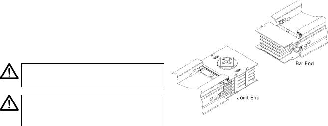
Establish the bus bar phase sequence (Ø side is labeled) to determine how the busway is to be installed, so that correct phasing is maintained throughout the system. Note that phase transposition lengths, when furnished, may relocate the Ø to the opposite side of a busway run.
Each busway piece has a ―bar end‖ and a ―joint end,‖ as illustrated in Figure 1. Normally the busway is oriented end for end with bar ends pointing away from the source. Also, the ø side should be oriented down for horizontal plug-in applications.
NOTE: No busway, including outdoor rated, is |
|
weatherproof until completely and properly |
|
installed. |
|
NOTE: Aucune canalisation pour barres omnibus, |
|
incluant celles classées pour l'extérieur, n'est à |
|
l'épreuve de l'eau jusqu'à ce qu'elle soit installée |
|
complètement et correctement. |
Figure 1. The bar end and joint end of the busway. |
|
Pre-Installation Procedure
When possible, deliver the busway to its installation location before unpacking. Large labels on each shipping carton or crate designate the items contained. Additionally, each busway piece is identified with an item number label.
Inspect each busway piece for possible damage or contamination. Contact surfaces must be clean. However, do not attempt to polish tarnished contact surfaces.
Check to ensure that joint insulators are not damaged or cracked and are firmly in place.
Megohm test each piece before installation.
In vertical riser installations, it is easier to lower the busway into place than it is to raise it.
If installation drawings have been furnished, information regarding the orientation of the busway and location of the ø side, as well as other pertinent data, will be furnished. These drawings should be followed carefully to ensure a proper busway system.
Where to Start
Start the installation, if at all possible, at the most critical point, such as a main feed box, switchboard or switchgear, elbow, or other critical fitting or termination.
3
Spectra and Spectra II Series™ Plug-In and Feeder Busway
Installing Spectra Series Busway
Obstructions
Where a busway run must pass through a wall or floor, an opening one inch larger than the busway cross-section should be provided. Joints may not occur inside walls or floors per the NEC. A flange is available to mask the opening after the busway is installed.
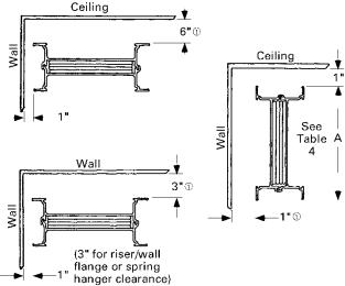
Minimum Clearances
Figure 2 illustrates the minimum clearances that must be maintained in various installation situations.
4‖ minimum provides clearance for 30–100 A fusible plugs. 7‖ minimum for 200 A fusible plugs. 8‖ minimum for all other plugs. See Tables 1, 2, and 3.
Figure 2. Minimum clearances to be maintained in various installations.
4

Spectra and Spectra II Series™ Plug-In and Feeder Busway
Installing and Removing Spectra Busway Plugs
Installing Indoor Busway
Horizontal Mounting
Overhead Support
For overhead-supported busway, 1/2-inch drop rods are recommended with a maximum 10-foot spacing. Drop rods and other hardware must be furnished by the installer. Figure 3 illustrates mounting dimensions for typical installations.
•Maintain good alignment of the drop rods along the busway run.
•Do not support busway at the joints.
•After the busway is secured in the hangers, adjust the hangers on the rods for the correct elevation.
•Sway braces (furnished by the installer) may be required to keep the run straight or to prevent rotation.
Table 4, Table 5 and Table 8. Select the spring hanger based on the seismic load; amperage and Vertical support spacing mentioned in table 1 & 2.
Table 1: Selection of spring hanger based on Seismic load and amperage.
Table 2: Selection of spring hanger based on Seismic load.
Wall or Column Support
Single-rod hangers, as shown in Figure 4, may be used for mounting busway on walls or columns with the addition of an angle support supplied by the installer.
Figure 3. Dimensions between drop rods for dual-hanger installations.
After placing the length of busway through the floor, follow this procedure to assemble hangers to the busway, as illustrated in Figure 5 Figure 6 & 6A. For convenience in assembly, step 8 may be completed before the hangers are attached to the busway.
NOTE: Check that the initial height is 8 inches, as shown in Figure 6.
NOTE: Veuillez vous assurer que la hauteur initiale est de 8 pouces, tel que montré à la Figure 6.
Figure 4. Single-rod hanger with one stack (a) (standard) mounted flat and (b) mounted edgewise.
Vertical Mounting
Support Busway on maximum 16-foot centers. Use Table 7 to determine the number of springs required based on busway weight, as listed in
1.Loosen the hanger bolt A, shown in Figure 5.
2.Assemble the hangers to each side of the busway.
3.Position the hangers on the busway so that the base channel (B) rests on the floor or other support. A floor flange (C) may be placed under the hanger, but it will not support the busway weight.
4.Fit the hanger clamps (G) to the busway housing and hand tighten the hanger bolts (A).
5.Anchor the base channels to their supports.
6.Tighten the hanger bolts (A).
5

Spectra and Spectra II Series™ Plug-In and Feeder Busway
Installing and Removing Spectra Busway Plugs
7.Install the next length and make the joint assembly (see the instructions for joining lengths below).
8.If springs are furnished, they must be adjusted as shown in Figure 6 at this time. Determine the required dimension H of the hanger springs, found on the layout drawing or by using the formula,
H = 55 8 – 150W
|
Busway wt / ft ft /floor + devices on floor |
W = |
Total number of springs / floor |
|
Using the final adjusting nuts (E), set the springs on the hangers to the dimension H. With the springs adjusted, hold nut (E) in position and tighten jam nut (F) against nut (E) to retain the spring setting. Tighten all jam nuts (F) using this procedure.
Note that when you are calculating the dimension H for the bottom floor of a riser with an elbow and busway directly below the floor, the following must be included in the footage calculation:
•Busway below the floor to the elbow,
•The elbow,
•8 feet of horizontal busway.
For the riser to function as a free end, the last horizontal hanger must be 8 feet from the bottom elbow.
9.After the busway run is installed and all ―H‖ dimensions are set to the required settings, starting at the top hanger raise the initial adjusting nuts (D) of all hangers to the top of the spring studs. The studs are crimped to hold the nuts in the uppermost position.
NOTE: Failure to properly adjust the spring hangers could damage the bus and void the warranty.
Figure 5. Rigid riser hanger installation.
Figure 6. Spring riser hanger installation
Figure 6A. Seismic Spring riser hanger installation (Cat No:
SBSR”X”)
6

Spectra and Spectra II Series™ Plug-In and Feeder Busway
Installing and Removing Spectra Busway Plugs
Table 3. Dimensions for Spectra RMS™ circuit breaker bus plug.
Frame |
Dimensions, in. |
Handle |
Wt., |
Outlets |
Fig. |
|||
W |
L |
D |
Ht . |
lb. |
||||
|
|
|
||||||
SED, SEH, SEL, SEP |
11.00 |
13.00 |
8.00 |
11.00 |
25 |
1 |
7 |
|
SFH, SFL, SFP |
11.00 |
21.25 |
9.00 |
12.00 |
41 |
1 |
7 |
|
SGH, SGL, SGP |
16.75 |
26.50 |
12.50 |
20.50 |
91 |
2 |
8 |
|
SKH. SKL, SKP |
16.75 |
36.50 |
12.50 |
20.50 |
160 |
2 |
8 |
|
Maximum distance from the busway housing to the handle tip.
For ground fault option, increase width by 2.125 inches and length by 6.00 inches.
Table 4. Dimensions for Types QMR and QMW fusible switch bus plugs, as illustrated in Figure and Figure 8.
|
|
|
Dimensions, in. |
|
|
|
|||
Rating, |
Amps |
|
|
L |
|
Handle |
Wt., |
Fig. |
|
W |
Std |
|
Ext |
D |
|||||
Volts |
|
|
Ht. |
lb |
|
||||
|
|
|
Gutter |
|
Gutter |
|
|
|
|
|
|
|
|
|
|
|
|
||
|
|
|
|
|
|
|
|
|
|
|
30 |
11.25 |
13.00 |
|
18.63 |
8.75 |
11.00 |
24 |
7 |
|
60 |
11.25 |
13.00 |
|
18.63 |
8.75 |
11.00 |
25 |
7 |
240 & |
100 |
11.25 |
18.75 |
|
NA |
8.75 |
11.00 |
28 |
7 |
600 |
200 |
16.00 |
18.75 |
|
24.50 |
8.75 |
11.00 |
46 |
7 |
|
400 |
20.50 |
18.75 |
|
NA |
18.75 |
24.00 |
135 |
8 |
|
600 |
20.50 |
24.50 |
|
NA |
18.75 |
28.00 |
160 |
8 |
Table 5. Dimensions for molded-case circuit breaker bus plugs.
|
|
|
Dimensions, in. |
Wt., |
|
|
|||
Frame |
|
|
|
Handle |
Outlets |
Fig. |
|||
W |
L |
D |
lb |
||||||
|
|
Height |
|
|
|||||
|
|
|
|
|
|
|
|
||
|
|
|
|
|
|
|
|
||
TEB, TED, THED |
11.00 |
13.00 |
8.00 |
11.00 |
24 |
1 |
7 |
||
TFJ, TFK, THFK |
11.00 |
18.50 |
9.50 |
12.00 |
44 |
1 |
7 |
||
TJJ, TJK4, TJK6, |
16.75 |
24.50 |
12.50 |
20.50 |
95 |
2 |
8 |
||
THJK4, THJK6 |
|
|
|
|
|
|
|
||
TKM8, |
THKM8, |
16.75 |
36.50 |
12.50 |
20.50 |
160 |
2 |
8 |
|
THK |
|
|
|
|
|
|
|
|
|
TB1 (fused) |
11.00 |
18.50 |
8.00 |
11.00 |
29 |
1 |
7 |
||
TB4 (fused) |
16.75 |
30.50 |
12.50 |
20.50 |
65 |
2 |
8 |
||
TB6 (fused) |
16.75 |
45.25 |
12.50 |
20.50 |
175 |
2 |
8 |
||
TB8 (fused) |
16.75 |
45.25 |
12.50 |
20.50 |
185 |
2 |
8 |
||
Table 6. Busway and hanger mounting dimensions, as illustrated in Figure 2 and Figure 3.
Bars per |
Ampere Rating |
Dimensions, in. |
||
Phase |
Copper |
Aluminum |
Busway A |
Hanger B |
|
225–800 |
225–600 |
43/8 |
|
|
1000 |
— |
5 |
|
|
1200 |
800 |
55/8 |
101/4 |
|
1350 |
1000 |
61/8 |
|
1 |
1600 |
1200 |
7 |
|
|
2000 |
1350 |
81/2 |
|
|
— |
1600 |
91/4 |
14 |
|
2500 |
— |
101/4 |
|
|
— |
2000 |
11 |
|
|
3000 |
— |
15 |
181/2 |
|
— |
2500 |
151/2 |
|
2 |
4000 |
3000 |
18 |
221/2 |
|
5000 |
— |
211/2 |
26 |
|
— |
4000 |
23 |
|
|
|
|||
Table 7. Number of busway springs required per busway weight.
Busway |
No. of Springs |
Weight, lb |
Required per Floor |
0–600 |
2 |
601–1200 |
4 |
Over 1200 |
6 |
Table 8. Busway weights.
|
|
Busway Weight, lb/ft |
|
|
Amperes |
Copper |
Aluminum |
||
|
3 Wire |
4 Wire |
3 Wire |
4 Wire |
225 |
8 |
9 |
5 |
6 |
400 |
8 |
9 |
5 |
6 |
600 |
8 |
9 |
5 |
6 |
800 |
8 |
9 |
6 |
7 |
1000 |
10 |
12 |
7 |
8 |
1200 |
12 |
15 |
8 |
9 |
1350 |
14 |
17 |
9 |
10 |
1600 |
16 |
20 |
10 |
12 |
2000 |
21 |
26 |
12 |
15 |
2500 |
26 |
33 |
17 |
20 |
3000 |
32 |
40 |
19 |
23 |
4000 |
42 |
52 |
25 |
30 |
5000 |
52 |
66 |
— |
— |
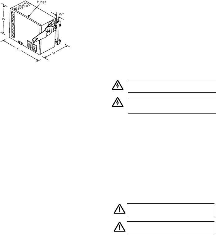
The door hinges at the left end. The L and W dimensions are shown over the largest part of the plug.
Figure 7. Bus plugs with door hinges at the left end.
Important Note:
On vertical riser applications use a Minimun of 18‖ of un-supported flexible conduit connecting to bus plugs.
7
Spectra and Spectra II Series™ Plug-In and Feeder Busway
Installing and Removing Spectra Busway Plugs
The door hinges at the top. The L and W dimensions are shown over the largest part of the plug.
Figure 8. Bus plugs with door hinges at the top.
Joining Lengths
Use the following procedure to join two lengths of busway.
1.Remove at least one joint cap, shown in Figure 9 and Figure 10, from the two pieces to be joined, retaining the bolts.
2.Align the sections to be joined by matching up the Ø SIDE labels attached to the ends of each section.
3.If necessary, loosen the joint bolt slightly.
4.Slide the sections together. Ensure that the busbars interweave the insulators, as shown in Figure 11, Figure 12, and Figure 13.
WARNING: The housing-ground side plates must pass between the outside insulators and the joint-ground side plates to avoid a phase-to-ground short circuit.
AVERTISSEMENT: Les plaques de côté reliant le boîtier à la mise à la terre doivent passer entre les isolateurs extérieurs et les plaques de côté du joint à la terre pour éviter un court -circuit de phase à la terre.
5.In nominal position, the standard distance between the joint cap bolt holes is 10 1/4 inches for outdoor busway, as shown in Figure 11. On indoor busway, the standard distance between the two housings is 8 3/8 inches, in nominal position, as shown in Figure 11. An alignment line marked ―N‖ on the joint cap window should line up with the edge of the housing at nominal position. However, the joint is also adjustable, as shown in Figure 12 and Figure 13. Simply move the sections in or out to the desired length, as shown, and remove the twist-outs in both joint caps (outdoor only) if needed, as shown in Figure 10.
NOTE: If any adjustments are made in Step 5, remove the shipping screws and center the joint between the two housings.
NOTE: Retirer les vis d'expédition et centrer le raccord entre les deux habitacles sitout ajustement est apporté à la fiche-boîtier à l'étape 5.
6.If the joint caps are not already in place, reattach them and hand-tighten the mounting screws.
7.When joining old-style indoor to new-style indoor busway, use a 3/8" x 1/2" bolt to attach
8

Spectra and Spectra II Series™ Plug-In and Feeder Busway
Installing and Removing Spectra Busway Plugs
the joint cap to the housing spacer of old-style indoor and the 5/16" x 2" bolt provided on the new-style indoor and attach to the U clip.
8.When joining Spectra Series Busway to Spectra II Plug-in Busway, a combination joint cap will be provided, use the 5/16‖ X 2‖ bolt to attach this joint cap to the Spectra Series Busway and the M10 X 16 bolts to attach the cap to the Spectra II Busway.
Figure 9. Indoor joint cap.
Figure 10. Outdoor joint cap.
Figure 11. Busway joint at the standard distance.
Figure 12. Busway joint at the minimum distance.
Figure 13. Busway joint at the maximum distance.
9.When joining Style II outdoor to new-style indoor busway, use the existing 3/8" x 1/2" bolt to attach the joint cap to the housing spacer of Style II outdoor and the 5/16" x 2" bolt provided on the new-style indoor and attach to the U clip.
10.Inspect the busway run for straightness in all planes and make any adjustments necessary for good alignment.
11.Grease has been applied to the joint bolt head and threads to reduce friction. Do not remove this grease.
12.Tighten the joint bolt with a 5/8‖ or 16-mm socket wrench until the smaller, top head breaks off. When the Belleville washers on both sides are flattened, the bolt is fully tightened. If the optional Joint-Guard™
9
 Loading...