


g
DEH–40031 Installation Instructions
ProTrip™ Conversion Kits
For Westinghouse® Type DB-25, DBL-
25, DB-50,
DBL-50 Low-Voltage Power Circuit
Breakers
INTRODUCTION
GE Conversion Kits are designed for upgrading existing Westinghouse® low-voltage power circuit breakers, rather than replacing the entire breaker. The Conversion Kits include ProTrip™ Trip Units, the latest advance in GE trip systems.
ProTrip Conversion Kits are designed and tested to conform to ANSI Standard C37.59, allowing the retrofitter to properly install the kit and acceptance test the breaker.
This publication covers installation of ProTrip™ Conversion Kits on Westinghouse Type DB-25, DBL-25, DB-50, and DBL-50 low-voltage power circuit breakers. Each Conversion Kit contains all the components needed to convert from an existing Westinghouse electromechanical trip system.
TABLE OF CONTENTS |
|
SECTION 1. GENERAL INFORMATION ........................................................................................................... |
4 |
SECTION 2. BEFORE INSTALLATION ............................................................................................................. |
4 |
SECTION 3. BACK FRAME BREAKER CONVERSION |
|
Removing the Electromechanical Trip Devices...................................................................................... |
5 |
Installing the Phase Sensors (CTs)........................................................................................................ |
8 |
SECTION 4. FRONT FRAME BREAKER CONVERSION |
|
Installing the Trip Paddle...................................................................................................................... |
11 |
Installing the Trip Unit Mounting Bracket.............................................................................................. |
12 |
Adjusting the Flux Shifter...................................................................................................................... |
14 |
Connecting the Trip Unit Wiring Harness............................................................................................. |
14 |
Installing the Trip Unit........................................................................................................................... |
15 |
Configuring the Trip Unit....................................................................................................................... |
15 |
SECTION 5. FOUR-WIRE GROUND FAULT OPTION................................................................................ |
16 |
SECTION 6. TESTING AND TROUBLE-SHOOTING |
|
Testing.................................................................................................................................................. |
18 |
Trouble-Shooting .................................................................................................................................. |
18 |
Nuisance Tripping on Ground Fault-Equipped Breakers ........................................................ |
18 |
2
LIST OF FIGURES |
|
|
1. |
Westinghouse DB-50 breaker removed from its enclosure and ready for conversion. ................................... |
5 |
2. |
Removal of the load-side draw-out fingers from a DB-25 breaker. ................................................................. |
5 |
3. |
Trip unit mounting bolts to be removed from a DB-50. .................................................................................... |
5 |
4. |
Trip unit mounting bolts to be removed from a DB-25. .................................................................................... |
6 |
5. |
Electromechanical trip devices removed from the breaker.............................................................................. |
6 |
6. |
DB-50 back frame with the electromechanical trip devices removed and ready for conversion. .................... |
7 |
7. |
Assembling a CT to the bus. ............................................................................................................................ |
8 |
8. |
CT assembly for a DB-50 breaker.................................................................................................................... |
8 |
9. |
CT assembly for a DB-25 breaker.................................................................................................................... |
8 |
10. |
CT alignment dowels installed on a DB-25 breaker......................................................................................... |
9 |
11. |
Placing a CT into position on a DB-50 breaker................................................................................................ |
9 |
12. |
CT bolts inserted into a DB-50 breaker back frame......................................................................................... |
9 |
13. |
CT bolts inserted into a DB-25 breaker back frame......................................................................................... |
9 |
14. |
CT assemblies installed into the breaker. ...................................................................................................... |
10 |
15. |
Tightening the CT assembly mounting bolts. on the rear of the breaker....................................................... |
10 |
16. |
Tightening the CT assembly bolts.................................................................................................................. |
10 |
17. |
Installing the trip paddle onto the trip bar....................................................................................................... |
11 |
18. |
Installing the reset sleeve onto the cross bar of a DB-25 breaker................................................................. |
11 |
19. |
Trip unit mounting bracket assembly. ............................................................................................................ |
12 |
20. |
Trip unit bracket installation. .......................................................................................................................... |
12 |
21. |
DB-25 flux shifter reset arm installed on the cross bar. ................................................................................. |
12 |
22. |
DB-25 spring clamp installed on the breaker frame....................................................................................... |
13 |
23. |
Drilling the flux shifter support bracket mounting hole. .................................................................................. |
13 |
24. |
Installed flux shifter and trip unit mounting assembly (DB-50)....................................................................... |
13 |
25. |
Adjusting the flux shifter. ................................................................................................................................ |
14 |
26. |
Wiring harness installed on the CTs. ............................................................................................................. |
14 |
27. |
Trip unit attached to its mounting plate. ......................................................................................................... |
15 |
28. |
Harness connector attached to the trip unit. .................................................................................................. |
15 |
29. |
Trip unit mounted on the breaker................................................................................................................... |
15 |
30. |
Neutral sensor outline for a DB-25 breaker ................................................................................................... |
16 |
31. |
Neutral sensor outline for a DB-50 breaker. .................................................................................................. |
17 |
32. |
Cabling diagram for ProTrip™ trip units with ground fault on four-wire loads ............................................... |
20 |
3

SECTION 1. GENERAL INFORMATION
GE Conversion Kit installation is straightforward, but does require careful workmanship and attention to these instructions. Familiarity with the breaker is highly desirable. Then general approach is to first remove the existing trip devices from the breaker, then install the ProTrip components. Following this procedure, the converted breaker is performance tested before it is returned to service.
The majority of trip unit kit installations do not require any customized assembly work. However, some installations may involve unusual mounting conditions or accessory combinations that require minor modifications and/or relocation of components. In most instances, this supplementary work can be done on site.
In preparation for the conversion, the installer should verify that the appropriate current sensors and trip unit have been furnished. Whenever a ProTrip kit is installed on a breaker with a four-wire system, an associated neutral sensor (CT) is required for separate mounting in the equipment. Ensure that retrofitted breakers are applied within their short-circuit ratings.
Note that all ProTrip trip units supplied with conversion kits are equipped with long-time, short-time, instantaneous, and defeatable ground fault (LSIGX) trip functions. The installer should be aware of how these functions will affect his application before installing the conversion kit.
As a service-related consideration, the installation of a ProTrip kit provides an excellent opportunity to perform normal maintenance on the breaker, particularly when the front and back frames are separated. Such procedures are described in the installation and maintenance manuals supplied with the breaker and equipment.
SECTION 2. BEFORE INSTALLATION
Before starting any work, turn off and lock out all power sources leading to the breaker, both primary and secondary. Remove the breaker to a clean, well-lighted work area.
WARNING: Low-voltage power circuit breakers use high-speed, stored-energy spring operating mechanisms. The breakers and their enclosures contain interlocks and safety features intended to provide safe, proper operating sequences. For maximum personnel protection during installation, operation, and maintenance of these breakers, the following procedures must be followed. Failure to follow these procedures may result in personal injury or property damage.
•Only qualified persons, as defined in the National Electrical Code, who are familiar with the installation and maintenance of low-voltage power circuit breakers and switchgear assemblies, should perform any work on these breakers.
•Completely read and understand all instructions before attempting any breaker installation, operation, maintenance, or modification.
•Turn off and lock out the power source feeding the breaker before attempting any installation, maintenance, or modification. Follow all lock-out and tag-out rules of the National Electrical Code and all other applicable codes.
•Do not work on a closed breaker or a breaker with the closing springs charged. Trip an OPEN breaker and be sure the stored-energy springs are discharged, thus removing the possibility that the breaker may trip OPEN or the closing springs discharge and cause injury.
•Trip the breaker OPEN, then remove the breaker to a well-lighted work area before beginning work.
•Do not perform any maintenance that includes breaker charging, closing, tripping, or any other function that could cause significant movement of a draw-out breaker while it is on the draw-out extension rails.
•Do not leave the breaker in an intermediate position in the switchgear compartment. Always leave it in the CONNECTED, TEST, or DISCONNECTED position. Failure to do so could lead to improper positioning of the breaker and flashback.
4

SECTION 3. BACK FRAME BREAKER CONVERSION
The back frame conversion of a Westinghouse® DB-25, DBL-25, DB-50, or DBL-50 breaker consists of the following steps:
1.Remove the breaker to a clean, well-lighted work bench and place it upright, so that both the front and back are easily accessible, as shown in Figure 1.
2.Remove the existing electromechanical trip devices.
3.Assemble the phase sensors (CTs) to their bus structures.
4.Install the CT assemblies on the breaker.
Removing the Electromechanical Trip
Devices
1.On a draw-out breaker, remove the load-side drawout contact fingers. Use a pair of pliers to squeeze the fingers and release them from the load terminals, as shown in Figure 2.
2.On both a DB-25 and DB-50 breaker, remove and discard the two 1/2-13 bolts above each load terminal, as shown in Figures 3 and 4.
Figure 1. Westinghouse DB-50 breaker removed from its enclosure and ready for conversion.
Load-Side
Draw-Out
Fingers
Figure 2. Removal of the load-side draw-out fingers from a DB-25 breaker.
1/2-13 Bolts
Figure 3. Trip unit mounting bolts to be removed from a DB-50.
5
3.On a DB-50 breaker, remove and discard the two 1/2- 13 bolts under each load terminal, as shown in Figure 3.
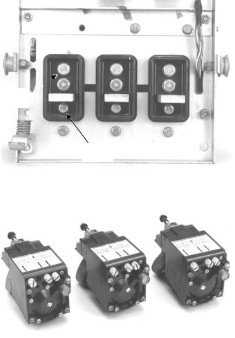
On a DB-25 breaker, remove and discard the single 3/8-16 bolt under each load terminal, as shown in Figure 4.
4.Remove the electromechanical trip devices, shown in Figure 5, from the frame and discard them. The back frame is now ready for conversion, as shown in Figure 6.
1/2-13  Bolts
Bolts
3/8-16 Bolt
Figure 4. Trip unit mounting bolts to be removed from a DB-25.
Figure 5. Electromechanical trip devices removed from the breaker.
6
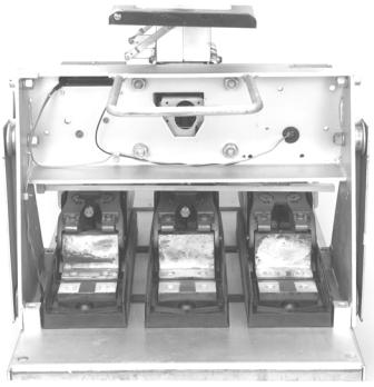
Figure 6. DB-50 back frame with the electromechanical trip devices removed and ready for conversion.
7
 Loading...