


 Loading...
HIGH SPEED DC CIRCUIT BREAKER
GERAPID 8007R, 10007R
WITH ARC CHUTES 1X2, 1X3
USERS GUIDE
2010-02-16 DTR01807 rev.02 |
Design and specifications are subject to change without notice |
1 |
2 |
Design and specifications are subject to change without notice |
DTR01807 rev.02 2010-02-16 |
INDEX
1. WARNINGS........................................................................................................ |
4 |
||
2. GENERAL USAGE CONDITIONS ................................................................ |
4 |
||
2.1 |
Transportation and storing ..................................................... |
4 |
|
2.2 |
Installation....................................................................................... |
5 |
|
2.2.1 Operational environment................................................. |
5 |
||
2.2.2 |
Installation and interfaces............................................... |
5 |
|
2.3 |
Usage................................................................................................. |
5 |
|
2.3.1 Supply and load ................................................................... |
5 |
||
2.3.2 Adjusting the over current release .............................. |
5 |
||
3. TECHNICAL INFORMATION ........................................................................ |
6 |
||
3.1 |
Introduction .................................................................................... |
6 |
|
3.2 |
Components and accessories................................................ |
6 |
|
3.2.1 Contact system .................................................................... |
6 |
||
3.2.2 Arc chute (Code 2)................................................................ |
6 |
||
3.2.3 Mechanism ............................................................................. |
6 |
||
3.2.4 Polarized over current release (Code 7) ................... |
7 |
||
3.2.5 ED impulse coil release (Code 12)................................. |
7 |
||
3.2.6 Auxiliary tripping devices (Code 11)............................ |
7 |
||
3.2.7 Forced tripping release (Code 13) ................................ |
8 |
||
3.2.8 Lever for manual operating (Code 16)...................... |
8 |
||
3.2.9 Auxiliary switches (Code 9).............................................. |
9 |
||
3.2.10 Indicators.............................................................................. |
9 |
||
3.2.11 Solenoid closing drive (Code 3) ................................... |
9 |
||
3.2.12 Electronic control system............................................. |
10 |
||
3.3 |
Technical data tables............................................................... |
11 |
|
4. ELECTRICAL CIRCUITS ................................................................................ |
13 |
||
4.1 |
Controls and plugs layout...................................................... |
13 |
|
4.2 |
Connectors for external wiring............................................ |
14 |
|
4.3 |
Electrical diagrams.................................................................... |
15 |
|
4.3.1 Wiring code........................................................................... |
15 |
||
4.3.2 Controls supply circuit..................................................... |
16 |
||
4.3.3 ED coil with external capacity bank ......................... |
17 |
||
4.3.4 NEKO control circuits ....................................................... |
18 |
||
4.3.5 |
SU control circuit................................................................ |
20 |
|
4.3.6 |
Shunt trip control circuit................................................. |
22 |
|
4.3.7 Zero voltage releases control circuit........................ |
23 |
||
4.3.8 Indicators............................................................................... |
24 |
||
4.3.9 Auxiliary switch................................................................... |
25 |
||
5. DIMENSIONS & SAFETY DISTANCES .................................................... |
26 |
|
5.1 |
Safety distances and outlined dimensions. .................. |
27 |
6. INSPECTIONS AND MAINTENANCE...................................................... |
29 |
|
6.1 |
List of inspections ...................................................................... |
29 |
6.1.1 General visual inspection............................................... |
30 |
|
6.1.2 General functional inspection...................................... |
30 |
|
6.1.3 Inspection of the arc chute........................................... |
30 |
|
6.1.4 Inspection of the contact system .............................. |
31 |
|
6.1.5 Inspection of contacts’ tilt and gap .......................... |
32 |
|
6.1.6 Inspection of the screw connections ....................... |
32 |
|
6.1.7 Inspection of the mechanical components .......... |
32 |
|
6.1.8 Checking the blockade of the POCT........................... |
32 |
|
6.2 |
List of maintenance works. ................................................... |
33 |
6.3 |
Spare parts lists.......................................................................... |
34 |
6.3.1 Mechanical spare parts.................................................. |
34 |
|
6.3.2 Electrical spare parts. ...................................................... |
34 |
|
7. CUSTOMER SUPPORT................................................................................. |
35 |
|
7.1 |
Options overview. ...................................................................... |
35 |
7.2 |
Ordering. ........................................................................................ |
36 |
7.3 |
Glossary ......................................................................................... |
37 |
7.4 |
Troubleshooting.......................................................................... |
38 |
7.5 |
GE service teams........................................................................ |
39 |
7.6 |
Notes................................................................................................ |
40 |
2010-02-16 DTR01807 rev.02 |
Design and specifications are subject to change without notice |
3 |
1. Warnings
Warnings:
During operation, electrical equipment carries dangerous voltages. In addition, circuit breaker emits hot, ionized gases when switching currents, especially short circuit currents.
Installing, commissioning, maintaining, changing or refitting of this equipment must be carried out only by qualified and suitably trained personnel and under strict observation of national and international applicable safety regulations.
During their operation, circuit breakers must be equipped with appropriately fitted covers, e.g. in suitable enclosures or panel boards. Safety distances must be preserved. Suitably trained service personnel shall only carry out certain works.
Non-compliance with these warnings may result in death, and/or severe physical damage and extensive damage to equipment.
Prior to carrying out maintenance, inspection or checks, the circuit breaker must be open, the both terminals must be grounded, the circuit breaker must be switched off and the control plugs removed.
Manual activation of the breaker while energized is forbidden. Manual activation must only be used for maintenance and inspection purposes, when breaker power is off and grounded.
The circuit breaker consists of high energy moving components. Do not touch the circuit breaker while it is being switched ON (closing) or OFF (opening). There is a high risk of major injury.
The control circuits may include capacitor banks, which can be charged with dangerous voltages. Work on this section must be carried out carefully.
2. General usage conditions
2.1 Transportation and storing
•The breaker is transported on wooden palette. It is fixed by shrunken plastic film. A cardboard box covers the breaker on the palette. Truck, railway, airplane and ship transport is possible. In case of sea transport, special protection against salty and humid environment is provided.
•The circuit breaker must always be transported to the installation site vertically and fully packed. The packaging protects the device against damage and dust; it should only be removed prior to installation.
•If the packaging is damaged, the breaker and the arc chute must be inspected for damage. Ensure that all packaging materials have been carefully removed prior to breaker installation.
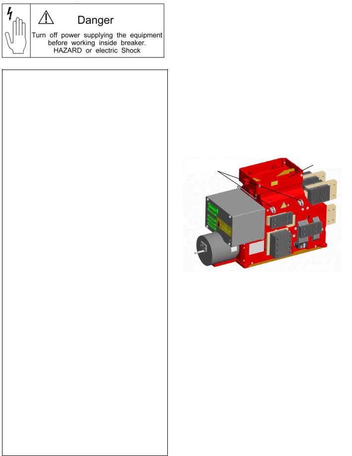
•For handling the unpacked breaker use the lifting rings provided [Fig.0]. The rings are located on both sides of the breaker. For lifting, it is recommended to use 4-leg wire rope slings of 1 m length (max. 8mm diameter) or 4-leg chain slings of 1.5 m length (max. 20 mm chain diameter).
Adaptor
Lifting rings
Fig. 0 Lifting rings for handling the breaker
•WARNING: Breaker and arc chute must be transported separately. Never handle the breaker with arc chute installed!
•Take care that the bottom isolation plate of the unpacked breaker is not damaged during handling. Do not push the breaker back and forth on any rough surface.
•The breaker’s weight, including arc chute is listed in Table 1. Arc chute’s weight is approximately 30 kG (66 lb) for “1x_” type.
WARNING:
•Store in original packaging!
•Do not store outdoors!
•Use protection against crush and impact!
•Do not store the breaker in a damp area!
•Storing temperature-range –25 °C…+60 °C!
4 |
Design and specifications are subject to change without notice |
DTR01807 rev.02 2010-02-16 |
2.2 Installation
2.2.1 Operational environment
•The breaker, as delivered, is IP00 (NEMA 1) protected. It is intended to work in indoor applications, without pollutions, with non-conductive dust, protected against high humidity and condensation. Low conductivity dust deposit due to frequent condensation of humidity is acceptable. General environmental conditions refer to EN 50123-1 - annex B, and IEC 60947, class PD3.
•The breaker can operate at rated current within ambient temperature range of –5 °C to +40 °C (23 to 104 °F).
Maximum operating ambient temperature is |
+55 °C |
(130 °F) with continuous current derated by 10 %. |
|
• The breaker can operate at altitude up to |
2000 m |
(~6500 ft) without derating. |
|
•The breaker shall not be subjected to strong vibrations. Maximum vibrations of 0.5 g per 30 sec are allowed. Resonance frequency is in range of 31 to 33 Hz.
•Air shall be clean and its relative humidity shall be not more than 50 % r.h. at the maximum temperature of +40 °C (104 °F). Relative humidity may be higher if the temperatures are lower, for example, 90 %r.h. at +20 °C (68 °F). Slight condensation might occur during variations of temperature
2.2.2 Installation and interfaces
•The lower and upper main terminals (Code 4) must be connected directly to the main cables or bus bars.
•WARNING: The breaker must only be used in an upright operation position with the arc chute in place and fully secured.
•After arc chute installation check for tightness both connections to the arc probes.
•The safety distances as listed in Table 4 shall be maintained to grounded or insulated parts. Suitable measures must be taken to protect personnel from arcs.
•Strong, external magnetic fields, caused by improperly located supply conductors or stray fields from other devices, can lead to a shift of the trip setting thresholds. This may result in premature tripping, or no tripping at all. This has to be accounted for when installing and operating the device with shielding added if appropriate.
•The control wires must be connected to the control terminals (Code 19), as shown in the schematic circuit diagrams in section 4. The protective grounding wire must be connected at the terminal –X2:3. This point is a common grounding for the drive and control box.
Fig. 1 Polarization markings on the lower main terminals.
2.3 Usage
2.3.1 Supply and load
•The breaker has polarized main connections. The marks are stamped at the ends of the main connections [Fig. 1]. The normal current flow, forward direction, is from plus to minus terminals and does not cause breaker to trip. The reverse current flow, from minus to plus, does cause the breaker to trip.
•In accordance with its type, the breaker has been designed for the current and voltage listed in Table 1.
•During continuous operation, breaker must only be loaded up to its maximum rated current. Load currents in excess of breaker nameplate rating are allowable for brief periods. Refer to the short time currents listed in Table 1.
•Do not exceed the rated operating voltage shown on the breaker’s nameplate.
•Supply voltage for the drive and the auxiliary-tripping devices (Code 8) shall be within the specified control voltage range. Maximum current values for the auxiliarytripping devices are listed in Table 2a.
•WARNING: Plugging in or unplugging of the auxiliary connectors (-X2 :1/:2) (-X3 :4/:5) is only allowed with disconnected primary (mains) and secondary voltages.
2.3.2 Adjusting the over current release
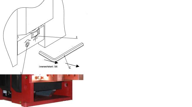
•POCT is a polarized over-current tripping release (Code 7), which trips and releases the breaker in case of over currents for one direction only.. This is an instantaneous and direct acting device.
•If equipped with an adjustable POCT, the response threshold can be easily adjusted [Fig.2], by turning the adjustment nut 1 with a SW6 hexagon wrench 2.
•The adjustment must only be carried out after the breaker has been disconnected from the main circuit. For fixed installations breaker’s main terminals shall be grounded.
•Turning the adjustment screw clockwise increases the trip threshold, turning the screw counter-clockwise decreases the tripping threshold.
•Align the arrow and the desired marking 3, to perform adjustment.
SW 6
Fig. 2 Setting of the POCT release
2010-02-16 DTR01807 rev.02 |
Design and specifications are subject to change without notice |
5 |
3. Technical information
3.1 Introduction
•Gerapid R-type (rectifier type) is a single pole, high-speed DC circuit breaker, designed for use in railway propulsion power distribution systems with operating currents up to 8000 A (Code 1) and operating voltages up to 1200 V (Code 2).
•Gerapid breaker has a very high interruption capacity combined with a current limiting characteristic. The arc chute works on the basis of an asbestos-free arc splitting principle.
•A wide variety of accessories and spares are available for maintenance, repair, or as a possible enhancement.
•Use the catalogue coding system described in section 7.1 to configure the breaker. Each rating, option or accessory has own code.
•Closing of the circuit breaker is performed through a highpower solenoid drive (Code 3).
•During inspections, opening and closing may be carried out by means of a hand lever (Code 16), which is mounted onto the armature of the closing drive.
•Tripping and release is obtained directly by means of the POCT release (Code 7), or optionally by ED impulse release (Code 12). Indirect remote tripping can be achieved by means of a shunt trip, or optionally by a zero voltage release (Code 11).
•Gerapid breakers have a compact and enclosed construction. Gerapid is IP 00 protected. All parts are mounted on thick-walled, non-breakable and fireproof insulation panels.
3.2 Components and accessories
3.2.1 Contact system
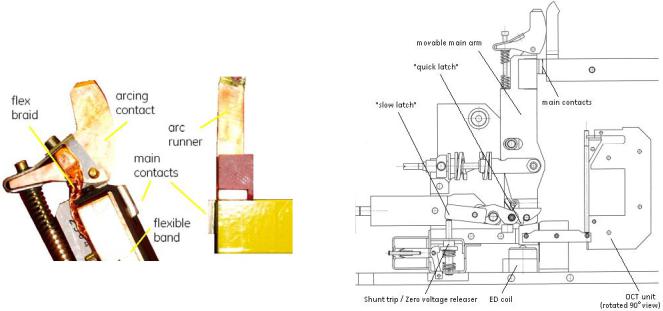
•Gerapid breakers are equipped with a two-stage contact system [Fig. 3], consisting of a main contact and an arcing contact. With this proven design, the main contact is not subjected to any appreciable wear or tear. Each breaker has two such contacts, working as a single pole.
•The main contact is made of a silver composite material. The arcing contact and link braid are made of copper and can be easily replaced.
•The flexible bend is linked to the arcing contact by means of very tight braid.
Fig. 3 Two-stage contact system
3.2.2 Arc chute (Code 2)
•Compact and modular design of the arc system requires no additional magnetic blow out support and allows small safety distances with high breaking capacity.
•An adaptor [Fig. 1] is used to mount the arc chute on the breaker.
•The arc chutes consist of a highly durable, arc-proof material, in which the arc plates have been integrated.
•The arc plates split the arc into partial arcs and increase the arcing voltage by multiplying the anode and cathode voltage drop. Because of their high heat capacity, the plates and arc chute walls absorb a large amount of the arc’s energy.
3.2.3 Mechanism
•Gerapid is equipped with a modular designed mechanism, which is wear-resistant and nearly maintenance-free. This mechanism ensures an extended electrical and mechanical endurance of the breaker as well as a high level of safety under all operation conditions.
•The breaker is rated for 10 000 operations when opened by the shunt trip or zero voltage release, and 500 operations by means of ED impulse coil or POCT releases, before maintenance should be required.
•The mechanism is mechanically latched in the CLOSED position. The principle of a mechanically latched mechanism offers an advantage compared to often used electro magnet holding system. No auxiliary control power source is required to keep breaker closed.
•The mechanism is provided with two tripping latches [Fig. 4]. First latch, called “slow latch”, is used for opening under normal conditions, like actuation of shunt trip or zero-voltage release. The second one, “quick latch”, declutches the main contact arm from the mechanism and opens the contacts with an extremely short delay. This is used when interrupting short-circuit or overloads. All safety releases operate onto “quick latch” latch.
•The mechanisms in rectifier breakers are the same type, but different from standard, feeder breakers mechanisms. Therefore mechanisms cannot be exchanged between rectifier and feeder breakers.
Fig. 4 Latching and tripping system
6 |
Design and specifications are subject to change without notice |
DTR01807 rev.02 2010-02-16 |
3.2.4 Polarized over current release (Code 7)
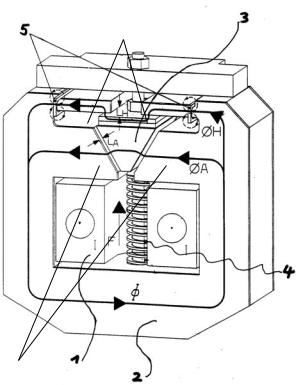
•The POCT release is a magnet with two magnetic circuits. The first one (tripping yoke) provides bi-directional tripping function. The second one (blocking yoke) provides unidirectional blocking function.
•This technology ensures fast tripping in reverse current direction and no tripping in case of forward current. This system does not require an auxiliary control voltage or protection relay to operate. It is a direct acting and instantaneous tripping device.
•The tripping yoke [Fig. 7] consists of the holding circuit [6], the movable armature [3] and the tripping circuit [7]. The holding and the tripping magnetic circuits are both excited by load current [1]. Until the static overload release’s response threshold has been reached, the armature [3] is held in position by the holding flux (ΦH) [2] and the counter spring’s force [4]. Once the load current exceeds the set static response threshold, the attraction flux (ΦA) [2] takes over and rapidly pulls down the flexible armature [3]. During this operation, the armature hits the seesaw, which releases the quick latch in the mechanism. The latch and contacts are opened immediately.
•The response threshold can be easily adjusted by turning the adjustment nut with a SW6 hexagon wrench. The available ranges are described below. Other ranges might be possible on request.
•The blocking system of POCT consists of main magnet circuit, permanent magnet oscillator and blockades. If the main current in forward direction exceeds 250A, the locking system starts to operate and counteracts tripping. This makes the breaker a unidirectional device.
•Following tripping ranges are available: 0.4-1.2 kA; 0.8- 2.5 kA; 2.0-6.0 kA; 4.0-8.0 kA.
6
7
Fig. 5 Tripping yoke of the POCT release.
3.2.5 ED impulse coil release (Code 12)
•To detect high short circuit currents early and to record leakage currents in long peripheral sections (for railway equipment), whose final values are lower than the highest operating currents, protective relays for monitoring a current increase should be utilized. If a fault occurs, a release signal can be passed on to the ED impulse coil and capacitor release (NEKO), which causes the breaker to open rapidly (opening delay <3ms).
•This tripping device can be ordered as an accessory for the breaker, either alternatively, or additionally to a shunt trip or a zero voltage release.
•ED impulse release requires an external protective relay for monitoring a current increase. This relay must be provided and installed by the customer.
•Customer supplied capacitor trip unit may be used. Rated voltage of 300 V and capacity of 2 000 µF per coil is required. Rectifier breakers utilize two ED coils.
•WARNING: ED Firing signal voltage level is between 6 V and 24 V. There should be no spikes on the signal of duration less 3 ms. This can lead to failure of the NEKO board!
•WARNING: Maximum duration of the firing signal must not exceed ~1 sec. Longer signal can lead to NEKO overheating! It is recommended to use an auxiliary contact in serial connection with firing circuits. It will automatically cut off the firing circuits after opening.
3.2.6 Auxiliary tripping devices (Code 11)
•The breaker can be equipped with either a shunt trip (ST, a-release) or a zero voltage release (UVR, r-release).
•Both trips work at a voltage level of 24VDC. A voltage transformer, which is integrated into the breaker, adapts to other voltage levels and provides the energy required by the breaker mechanism (except for the drive).
•Optionally, it’s possible to supply both devices directly to external 24 V DC ( ± 5%). In this case the release signal for ST shall not be longer 100 ms.
•The shunt trip is used for remote actuation. It is designed for intermittent operation (ED=9%) and is always connected through an auxiliary contact to ensure that is only energized during the time until the breaker is opened.
•The UVR’s winding is designed for continuous operation. In case of a control voltage drop, the release mechanism opens the breaker. It is therefore possible to use the release in combination with the electronic trip unit for voltage monitoring, i.e. for motor starters, where an unintended re-start of a motor after a temporary voltage breakdown is to be prevented. Due to their operational mode, UVRs are self-monitoring devices, i.e. the breaker is tripped upon a break of the pilot wire (EMERGENCY-OFF principle).
•WARNING: Manual closing of the breaker with shunt trips installed, while signal OPEN is active and control power is applied, may lead to shunt coil overheating and damage.
2010-02-16 DTR01807 rev.02 |
Design and specifications are subject to change without notice |
7 |

3.2.7 Forced tripping release (Code 13)
•Optionally, the forced tripping release (FT) can be installed in the breaker [Fig. 6]. This mechanical trip releases the breaker, by pressing the pin located in the bottom plate. Force required to trip the breaker is about 110 N (~25 ftlb). The tripping pin position is shown on Fig. 6.
•WARNING: This device, when active, does not prevent breaker from closing. Closing the breaker against activated FT may lead to damage of this release.
•With a correctly designed interlock in an enclosure, FT provides safety-tripping function. During withdrawal operation of the trolley, the breaker is tripped BEFORE its main terminals disconnect from the bus.
Bottom view
Fig. 6 Forced tripping release
3.2.8 Lever for manual operating (Code 16)
•Optionally, a hand lever for manual closing and opening operation during maintenance is available. This tool must not be use while breaker is energized!
•To close the contacts, install hand lever (1) on the drive’s rod, and pull it out smoothly until latches snap [Fig. 7]. Safe manual closing is shown on the Fig. 26, chapter 6.1.2.
•To open the contacts, insert lever’s pin (3) into the ring (2) and push it hard until breaker opens [Fig. 8] and [Fig 27].
•WARNING: Manual closing and opening – only during maintenance!
•Alternative manual closing and opening operation is possible by rotating the main shaft of the breaker mechanism, which is accessible from both side. Use 10 mm hexagon-box wrenches to OPEN/CLOSE [Fig. 9]. To close the breaker, shafts from both sides have to be rotated simultaneously.
•WARNING: Pay attention to control rotation speed of the shaft during manual opening and closing. Impede the wrench to avoid hitting it to the ground, which may lead to a hand injury.
Fig. 7 Closing operation by using a hand lever
Fig. 8 Opening operation by using hand lever
CLOSE
OPEN
Fig. 9 ON/OFF operation by means of a 10 mm wrench
8 |
Design and specifications are subject to change without notice |
DTR01807 rev.02 2010-02-16 |
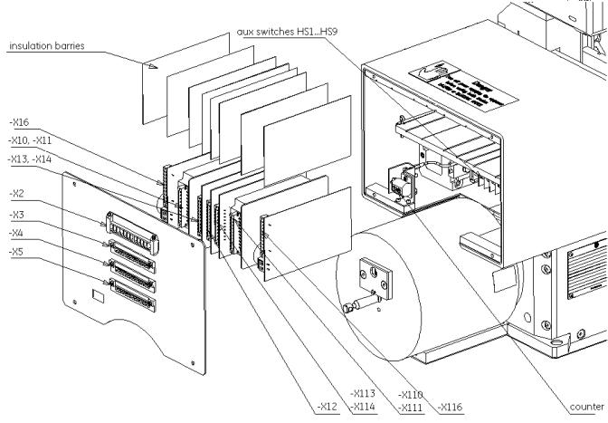
3.2.9 Auxiliary switches (Code 9)
•The breaker can be equipped with up to nine isolated form C auxiliary contacts (1 NO/NC each) [Fig. 10]. The contacts are activated by breaker’s main mechanism.
•The contacts are wired to 15-pin control plugs: -X4 and - X5, with 5 switches to each plug.
•Conventional thermal current Ith=10 A. Maximum electrical interrupting ratings for switches are 1 A/230 V for AC15. For DC13 are 0.5 A/110 V and 0.3 A/220 V.
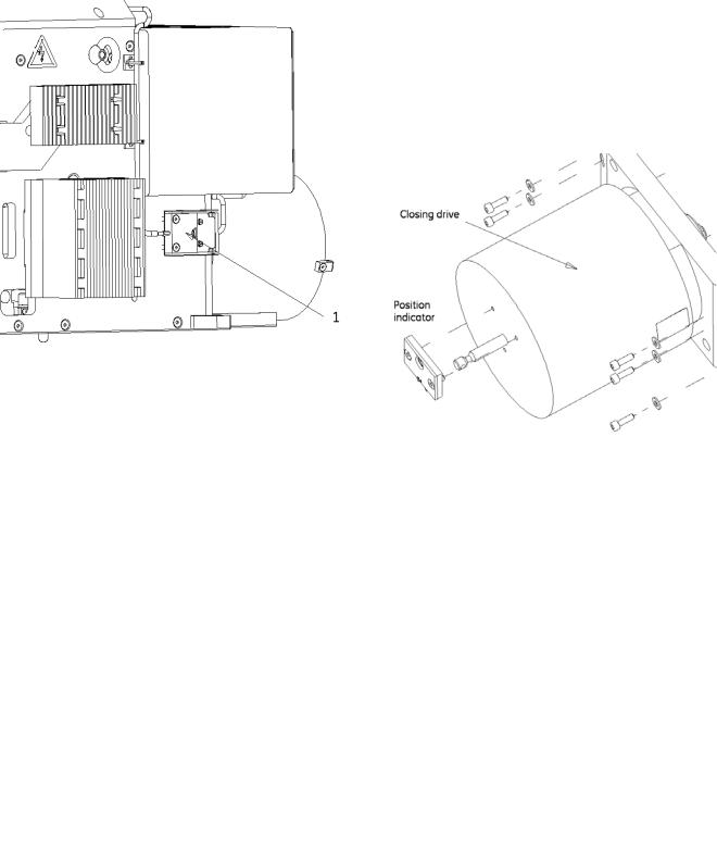
3.2.11 Solenoid closing drive (Code 3)
•The closing drive is mounted at the front of the breaker and is encased in a grounded casing [Fig. 12].
•The closing drive includes a self-interrupt control circuit (SU PCB). This circuit enables a short activation with minimum command duration of approximately 100ms, causing the voltage applied to the solenoid to be switched off after approximately 400ms and prevents, during continuous operation, repeated reclosing (anti-pumping) due to an existing short circuit.
•Closing drive is supplied independently from other controls (-X2 :1/:2), directly from external power source. Voltage level must be defined at order placement. Rated power, depends on breaker type, is 3 kW or 4.5 kW.
•After closing attempt, the switch-in mechanism is electrically blocked for approximately 8 sec. Lock time increases to 14 sec, if internal C-bank (NEKO) is present. This prevents premature closing following a short circuit.
Fig. 10 Auxiliary switches block in the control box.
3.2.10 Indicators
Optionally, the circuit breaker can be equipped with following indicators:
•POSITION INDICATOR (Code 14) - mounted at the front of the closing drive [Fig. 12]. Moving drive’s rod is mechanically switching the indicator.
“OPEN” or “O” – means open main contacts “CLOSED” or “I” – means closed main contacts
•OC TRIP TARGET (Code 10) – a potential free, NO contact mounted at the top of the OCT [Fig. 14]. Provides a signal when OCT trips.
•ARC CHUTE INDICATOR (Code 17) – a potential free, NO contact mounted on the sidewall, item (1) on Fig. 11. Locks electrically the closing drive when arc chute is not installed on. The signal is available at terminal –X3 :12:13.
Fig. 11 Closing drive with position indicator.
Fig. 12 Closing drive with position indicator.
2010-02-16 DTR01807 rev.02 |
Design and specifications are subject to change without notice |
9 |

• (3) SU control unit.
3.2.12 Electronic control system
All the control PCBs are installed in control box [Fig. 13].
Starting from the left, these are:
1 |
2 |
3 |
4 |
3 |
2 |
1 |
Fig. 13-3 SU control unit.
• (4) ST (a- trip) and UVR (r- release) control unit..
Fig. 13 Control box with control PCBs.
•(1) NEKO control unit [Fig. 13-1] (Code 12) – internal control unit with capacitor bank. Releases firing signal for ED coil and provides indication of the capacitors charging. NEKO control unit also blocks the firing signal until C-bank is fully charged (~15 sec).
•WARNING: NEKO unit requires a high quality signal. Be sure, that voltage level is between 6 V…24 V DC and there are no short spikes on signal (<3 ms). This may lead to major defect of the NEKO control unit!
Fig. 13-1 NEKO control unit
•(2) Internal voltage converter (Code 8) - converts external supply voltage (-X3 :4/:5) to the internal 24 V DC. Required by controls (except for the drive supply).
Fig. 13-2 Voltage converter 110 V/24 V DC.
Fig. 13-4 UVR control unit
Fig. 13-5 ST control unit
10 |
Design and specifications are subject to change without notice |
DTR01807 rev.02 2010-02-16 |
3.3 Technical data tables
Table 1. Technical data, type Gerapid 8007R & Gerapid 10007R
Parameter |
Reference |
Gerapid 8007 R |
Gerapid 10007 R |
||
Arc chute type |
N/A |
1x2 |
1x3 |
1x2 |
1x3 |
Rated continuous current [A] |
ANSI C37.14 p.5.3 |
6.000 |
6.000 |
8.000 |
8.000 |
2 hours current [A] |
N/A |
7.200 |
7.200 |
9.600 |
9.600 |
2 minutes current [A] |
N/A |
12.000 |
12.000 |
16.000 |
16.000 |
20 seconds current [A] |
N/A |
18.000 |
18.000 |
24.000 |
24.000 |
Rated short-time current (250ms) [kA] |
ANSI C37.14 p.5.5 |
90 (149 peak) |
60 (100 peak) |
90 (149 peak) |
60 (100 peak) |
Rated maximum voltage [V] |
ANSI C37.14 p.5.2 |
800 |
1200 |
800 |
1.200 |
Rated insulation voltage - UNm [V] |
EN 50124-1 p.1.3.2.4 |
2.000 |
2.000 |
2.000 |
2.000 |
Rated impulse voltage - UNi [kV] |
EN 50124-1 p.1.3.2.7 |
18 [1,2/50 µs] |
18 [1,2/50 µs] |
18 [1,2/50 µs] |
18 [1,2/50 µs] |
Power frequency voltage – Ua [kV] |
EN 50124-1 a.B 2.2 |
10 [1 minute 50 Hz] |
10 [1 minute 50 Hz] |
10 [1 minute 50 Hz] |
10 [1 minute 50 Hz] |
Mechanical endurance [cycles] a) |
N/A |
10.000 |
10.000 |
10.000 |
10.000 |
Rated short circuit peak / sustained current [kA] c) |
ANSI C37.14 p.5.4 |
200 / 120 |
132 / 80 |
200 / 120 |
132 / 80 |
Short-circuit characteristic |
Tests a, b, c, d ANSI C37.14 annex A |
High-speed |
High-speed |
High-speed |
High-speed |
Maximum arc voltage [V] |
N/A |
2.500 |
2.500 |
2.500 |
2.500 |
Mass ca. |
N/A |
220 kG |
220 kG |
220 kG |
220 kG |
a) 10.000 cycles without parts replacement. Inspection after 5.000 cycles. Max. 5.000 cycles by means of ED impulse coil or POCT release.
c) Trip by means of POCT (direct-acting, instantaneous, electromechanical and polarized OC release) or by means of ED impulse coil with no intentional delay.
2010-02-16 DTR01807 rev.02 |
Design and specifications are subject to change without notice |
11 |

Control box terminals |
(1) 12-pole |
|
|
|
AC 400 V, 20 A |
|
|
(4) 15-pole |
|
|
|
AC 250 V, 8 A |
|
Closing solenoid drive1) |
Rated voltage |
|
|
|
AC 110 V - 240 V |
and DC 60 V - 250 V |
|
Operating range |
|
|
|
80 % - 115 % of rated voltage |
|
|
Power consumption |
60 Vdc drive |
3000 W |
|
||
|
Power consumption |
all other voltages |
4500 W |
|
||
|
Minimum command signal time |
100 ms |
|
|||
|
Minimum interval between two closing operations |
~8 s w/o NEKO installed; ~14 s with NEKO |
||||
Internal voltage converter 1) |
Input: |
|
|
Voltage range |
DC 33 - 85 V |
|
|
Output: |
|
|
Voltage range |
DC 24 V (±5%) |
|
|
|
|
|
Current |
6 A continuous |
|
|
Model description |
|
|
|
PCMD 150 48 S24W-GE |
|
|
|
|
|
|
|
|
|
Input: |
|
|
Voltage range |
DC 88 - 145 V |
|
|
Output: |
|
|
Voltage range |
DC 24 V (±5%) |
|
|
|
|
|
Current |
6 A continuous |
|
|
Model description |
|
|
|
PCMD 150 110 S24W-GE |
|
|
|
|
|
|
|
|
|
Input: |
|
|
Voltage range |
AC 115 - 240 V, |
DC 125 - 353 V |
|
Output: |
|
|
Voltage range |
DC 24 V (±5%) |
|
|
|
|
|
Current |
3 A continuous, |
5 A for 100 ms |
|
Model description |
|
|
|
PCMA 70 S24W-GE or PCMAS 75 S24-GE |
|
External power supply |
with plug and socket unit |
|
requires filtered DC 24 V (±5%) |
|||
Aux. contact HS 1…HS 10, |
Rated operational voltage |
Ue/AC |
230 V |
|
||
OC trip target (code 10) |
Rated operational current |
Ie/AC-15 |
1 A |
|
||
Arc chutes indicator (code 17) |
Conventional thermal current |
Ie/AC-12 (Ith) |
10 A |
|
||
|
Rated operational voltage |
Ue/DC |
110 V / 220 V |
|
||
|
Rated operational current |
Ie/DC-13 |
0.5 A / 0.3 A |
|
||
|
Minimum current/voltage ratings |
0,1 mA / 6 V DC |
|
|||
|
Contact duty (min. value) |
|
DC 10 V / 2 mA |
|
||
Shunt trip (a-release) |
Rated voltage/power |
|
Uc/Pc |
24 V / 100 W |
|
|
|
Operating range: OFF |
|
|
21.6 V - 26.4 V |
|
|
UVR (r-release) |
Rated voltage |
|
|
Uc |
24 V |
|
Zero voltage release |
Operating range: OFF |
|
|
< 4 V |
|
|
|
Operating range: ON |
|
|
24 V (±10%) |
|
|
|
Power consumption |
|
|
~ 10 W |
|
|
ED impulse release |
Energie source: Capacity |
|
2000 µF |
|
||
|
Charging voltage |
|
|
|
300 V |
|
|
Switching interval |
|
|
|
max. 1/min with 10 consecutive operations |
|
|
Endurance |
|
|
|
1 000 operations with 1 operation per 180 s |
|
|
Firing signal |
level / duration |
6 - 24 V / 100 - 1000 ms |
|||
|
Charging signalization relay |
AC duty : |
AC 250 V/ 0.5 A - AC 120 V /1 A |
|||
|
|
|
|
DC duty : |
DC 220V/0.1A - DC 125V/0.3A - DC 10V/3A |
|
1) Standard ambient conditions acc. to EN 50123-1 Attachement B. For meeting outside of this standard range, please contact GE.
Table 2a: Technical data of auxiliary circuits
Components |
|
Technical datas of control circuits |
|
|
|
|
Us / In |
Closing |
push-button -S1 (-X2 :4 / :5) |
DC 24 V / approx. 10 mA |
|
ST releasing |
push-button-S2 (-X2 :6 / :7) |
DC 24 V / approx. 4 A |
|
UVR releasing |
push-button -S2 |
( -X2 :6 / :7) |
DC 24 V / approx. 10 mA |
|
push-button -S2 |
( -X2 :8 / :9 ) |
DC 24 V / approx. 450 mA |
Impulse coil tripping w/o NEKO |
push-button -S3 |
(R=0.18 Ohm, Tau = 0.5ms) |
DC 300 V / ~1100 A / 3 ms |
Impulse coil tripping with NEKO |
"firing signal" at ( -X2 :10 / :11 ) |
DC 6 V…24 V / approx.20 mA |
|
Table 2b: Control circuits ( directional values to rate the components )
12 |
Design and specifications are subject to change without notice |
DTR01807 rev.02 2010-02-16 |
4. Electrical circuits
4.1 Controls and plugs layout
Description |
Designation |
|
|
X2 |
Connector: Auxiliaryand control circuits |
X3 |
Connector: Auxiliaryand control circuits |
X4 |
Connector: Auxiliary contacts HS1...HS5 |
X5 |
Connector: Auxiliary contacts HS6...HS9 |
X10; X110 |
Control board: Voltage converter |
X11; X111 |
Control board: Interface for external DC 24V supply (OPTION) |
X12 |
Control board: SU control unit |
X13, X113 |
Control board: Shunt trip control unit |
X14, X114 |
Control board: Zero voltage release control unit |
X16; X116 |
Control board: NEKO control unit for ED impulse coil |
Fig. 14 Controls and plugs layout
2010-02-16 DTR01807 rev.02 |
Design and specifications are subject to change without notice |
13 |
Loading...