


GE
Entellisys™ Low Voltage Switchgear
System Test Kit
User Manual

DEH-233
Warnings, Cautions, and Notes as used in this publication
Warnings
WARNING! Warning notices are used in this publication to emphasize that hazardous voltages, currents, or other conditions that could cause personal injury exist in this equipment or may be associated with its use.
Warning notices are also used for situations in which inattention or lack of equipment knowledge could cause either personal injury or damage to equipment.
Cautions
CAUTION: Caution notices are used for situations in which equipment might be damaged if care is not taken.
Notes
NOTE: Notes call attention to information that is especially significant to understanding and operating the equipment.
This document is based on information available at the time of its publication. While efforts have been made to ensure accuracy, the information contained herein does not cover all details or variations in hardware and software, nor does it provide for every possible contingency in connection with installation, operation, and maintenance. Features may be described in here that are not present in all hardware and software systems. GE Consumer & Industrial assumes no obligation of notice to holders of this document with respect to changes subsequently made.
GE Consumer & Industrial makes no representation or warranty, expressed, implied, or statutory, with respect to, and assumes no responsibility for the accuracy, completeness, sufficiency, or usefulness of the information contained herein. No warrantees of merchantability or fitness for purpose shall apply.
Entellisys™, EntelliGuard™, and FlexLogic™ are trademarks of the General Electric Company.
Modbus RTU is a registered trademark of AEG Schneider Automation.
©Copyright 2005 General Electric
All Rights Reserved
How to contact us
Please have your Entellisys System Summary # and Sub # ready when calling. This information can be found on the Entellisys HMI on the System Health screen by clicking the Job Info button.
Post Sales Service
GE Switchgear
510 Agency Road
West Burlington, IA 52655
Phone (toll free): 1-888-437-3765
Additional information: www.entellisys.com/support
Contents
1 System Test Kit
1.1 Introduction. . . . . . . . . . . . . . . . . . . . . . . . . . . . . . . . . . . . . . . . . . . . . . . . . . . . . . . . . . . . . . . . . . . . . . . . . . . . . . . . . . . . . . . . . . . 7 1.2 Test overview/architecture. . . . . . . . . . . . . . . . . . . . . . . . . . . . . . . . . . . . . . . . . . . . . . . . . . . . . . . . . . . . . . . . . . . . . . . . . . . . 10 1.3 Test kit hardware/specs . . . . . . . . . . . . . . . . . . . . . . . . . . . . . . . . . . . . . . . . . . . . . . . . . . . . . . . . . . . . . . . . . . . . . . . . . . . . . . 11 1.3.1 Test Unit PC . . . . . . . . . . . . . . . . . . . . . . . . . . . . . . . . . . . . . . . . . . . . . . . . . . . . . . . . . . . . . . . . . . . . . . . . . . . . . . . . . . . . . 11 1.3.2 Test kit power cord . . . . . . . . . . . . . . . . . . . . . . . . . . . . . . . . . . . . . . . . . . . . . . . . . . . . . . . . . . . . . . . . . . . . . . . . . . . . . . 11 1.3.3 Test connector (System Test Kit to EntelliGuard Messenger cable). . . . . . . . . . . . . . . . . . . . . . . . . . . . . . . . . . 12 1.3.4 USB-to-USB cable . . . . . . . . . . . . . . . . . . . . . . . . . . . . . . . . . . . . . . . . . . . . . . . . . . . . . . . . . . . . . . . . . . . . . . . . . . . . . . . 12 1.4 Getting started . . . . . . . . . . . . . . . . . . . . . . . . . . . . . . . . . . . . . . . . . . . . . . . . . . . . . . . . . . . . . . . . . . . . . . . . . . . . . . . . . . . . . . . 13 1.4.1 Start up . . . . . . . . . . . . . . . . . . . . . . . . . . . . . . . . . . . . . . . . . . . . . . . . . . . . . . . . . . . . . . . . . . . . . . . . . . . . . . . . . . . . . . . . . 13 1.4.2 Self Test. . . . . . . . . . . . . . . . . . . . . . . . . . . . . . . . . . . . . . . . . . . . . . . . . . . . . . . . . . . . . . . . . . . . . . . . . . . . . . . . . . . . . . . . . 14 1.4.3 Main Menu . . . . . . . . . . . . . . . . . . . . . . . . . . . . . . . . . . . . . . . . . . . . . . . . . . . . . . . . . . . . . . . . . . . . . . . . . . . . . . . . . . . . . . 15 1.4.4 General navigation . . . . . . . . . . . . . . . . . . . . . . . . . . . . . . . . . . . . . . . . . . . . . . . . . . . . . . . . . . . . . . . . . . . . . . . . . . . . . . 16 1.5 Download switchgear configuration. . . . . . . . . . . . . . . . . . . . . . . . . . . . . . . . . . . . . . . . . . . . . . . . . . . . . . . . . . . . . . . . . . . 16 1.5.1 Direct Connect Download from HMI . . . . . . . . . . . . . . . . . . . . . . . . . . . . . . . . . . . . . . . . . . . . . . . . . . . . . . . . . . . . . . 17 1.5.1.1 System Configuration Download Link communication. . . . . . . . . . . . . . . . . . . . . . . . . . . . . . . . . . . . . . . . 20 1.5.2 Last Download . . . . . . . . . . . . . . . . . . . . . . . . . . . . . . . . . . . . . . . . . . . . . . . . . . . . . . . . . . . . . . . . . . . . . . . . . . . . . . . . . . 20
1.6 Test Menu. . . . . . . . . . . . . . . . . . . . . . . . . . . . . . . . . . . . . . . . . . . . . . . . . . . . . . . . . . . . . . . . . . . . . . . . . . . . . . . . . . . . . . . . . . . . 21 1.6.1 Overcurrent Protection Test . . . . . . . . . . . . . . . . . . . . . . . . . . . . . . . . . . . . . . . . . . . . . . . . . . . . . . . . . . . . . . . . . . . . . . 22 1.6.1.1 Functions . . . . . . . . . . . . . . . . . . . . . . . . . . . . . . . . . . . . . . . . . . . . . . . . . . . . . . . . . . . . . . . . . . . . . . . . . . . . . . . . . . 22 1.6.1.2 Test methods . . . . . . . . . . . . . . . . . . . . . . . . . . . . . . . . . . . . . . . . . . . . . . . . . . . . . . . . . . . . . . . . . . . . . . . . . . . . . . 23 1.6.1.3 Pre-Defined Overcurrent Protection Test. . . . . . . . . . . . . . . . . . . . . . . . . . . . . . . . . . . . . . . . . . . . . . . . . . . . . 23 1.6.1.4 User-Defined Overcurrent Protection test. . . . . . . . . . . . . . . . . . . . . . . . . . . . . . . . . . . . . . . . . . . . . . . . . . . . 26 1.6.1.5 Automatic Trip Time Curve Test . . . . . . . . . . . . . . . . . . . . . . . . . . . . . . . . . . . . . . . . . . . . . . . . . . . . . . . . . . . . . 29 1.6.2 Relay Protection Test . . . . . . . . . . . . . . . . . . . . . . . . . . . . . . . . . . . . . . . . . . . . . . . . . . . . . . . . . . . . . . . . . . . . . . . . . . . . 32 1.6.2.1 Pre Defined Test . . . . . . . . . . . . . . . . . . . . . . . . . . . . . . . . . . . . . . . . . . . . . . . . . . . . . . . . . . . . . . . . . . . . . . . . . . . . 34 1.6.2.2 User Defined Test. . . . . . . . . . . . . . . . . . . . . . . . . . . . . . . . . . . . . . . . . . . . . . . . . . . . . . . . . . . . . . . . . . . . . . . . . . . 37 1.6.2.3 Relay Protection Test Results screen . . . . . . . . . . . . . . . . . . . . . . . . . . . . . . . . . . . . . . . . . . . . . . . . . . . . . . . . 41
1.7 Ground Fault Defeat . . . . . . . . . . . . . . . . . . . . . . . . . . . . . . . . . . . . . . . . . . . . . . . . . . . . . . . . . . . . . . . . . . . . . . . . . . . . . . . . . . 42 1.7.1 Setup . . . . . . . . . . . . . . . . . . . . . . . . . . . . . . . . . . . . . . . . . . . . . . . . . . . . . . . . . . . . . . . . . . . . . . . . . . . . . . . . . . . . . . . . . . . 43 1.8 Summary of Protection . . . . . . . . . . . . . . . . . . . . . . . . . . . . . . . . . . . . . . . . . . . . . . . . . . . . . . . . . . . . . . . . . . . . . . . . . . . . . . . 44 1.9 Manual Breaker Injection . . . . . . . . . . . . . . . . . . . . . . . . . . . . . . . . . . . . . . . . . . . . . . . . . . . . . . . . . . . . . . . . . . . . . . . . . . . . . 45 1.9.1 Setup . . . . . . . . . . . . . . . . . . . . . . . . . . . . . . . . . . . . . . . . . . . . . . . . . . . . . . . . . . . . . . . . . . . . . . . . . . . . . . . . . . . . . . . . . . . 46 1.9.2 Manual circuit breaker injection input range . . . . . . . . . . . . . . . . . . . . . . . . . . . . . . . . . . . . . . . . . . . . . . . . . . . . . . 47 1.10 Post Analysis Selection screen . . . . . . . . . . . . . . . . . . . . . . . . . . . . . . . . . . . . . . . . . . . . . . . . . . . . . . . . . . . . . . . . . . . . . . . 48 1.11 Test Reports . . . . . . . . . . . . . . . . . . . . . . . . . . . . . . . . . . . . . . . . . . . . . . . . . . . . . . . . . . . . . . . . . . . . . . . . . . . . . . . . . . . . . . . . 48 1.12 Test kit administration . . . . . . . . . . . . . . . . . . . . . . . . . . . . . . . . . . . . . . . . . . . . . . . . . . . . . . . . . . . . . . . . . . . . . . . . . . . . . . . 51 1.12.1 HMI setup. . . . . . . . . . . . . . . . . . . . . . . . . . . . . . . . . . . . . . . . . . . . . . . . . . . . . . . . . . . . . . . . . . . . . . . . . . . . . . . . . . . . . . 52 1.12.2 Disk cleanup . . . . . . . . . . . . . . . . . . . . . . . . . . . . . . . . . . . . . . . . . . . . . . . . . . . . . . . . . . . . . . . . . . . . . . . . . . . . . . . . . . . 53 1.12.3 System Information . . . . . . . . . . . . . . . . . . . . . . . . . . . . . . . . . . . . . . . . . . . . . . . . . . . . . . . . . . . . . . . . . . . . . . . . . . . . 54 1.12.4 Test Kit Validation Test . . . . . . . . . . . . . . . . . . . . . . . . . . . . . . . . . . . . . . . . . . . . . . . . . . . . . . . . . . . . . . . . . . . . . . . . . 55 1.12.4.1 Customer Validation Tests . . . . . . . . . . . . . . . . . . . . . . . . . . . . . . . . . . . . . . . . . . . . . . . . . . . . . . . . . . . . . . . . . 55 1.12.4.2 Factory Test only. . . . . . . . . . . . . . . . . . . . . . . . . . . . . . . . . . . . . . . . . . . . . . . . . . . . . . . . . . . . . . . . . . . . . . . . . . 56 1.13 Long-term maintenance. . . . . . . . . . . . . . . . . . . . . . . . . . . . . . . . . . . . . . . . . . . . . . . . . . . . . . . . . . . . . . . . . . . . . . . . . . . . . 56 1.13.1 Motherboard battery maintenance . . . . . . . . . . . . . . . . . . . . . . . . . . . . . . . . . . . . . . . . . . . . . . . . . . . . . . . . . . . . . 56
Contents 5
1.13.2 Test kit care. . . . . . . . . . . . . . . . . . . . . . . . . . . . . . . . . . . . . . . . . . . . . . . . . . . . . . . . . . . . . . . . . . . . . . . . . . . . . . . . . . . . 57 1.13.2.1 Handling the test kit . . . . . . . . . . . . . . . . . . . . . . . . . . . . . . . . . . . . . . . . . . . . . . . . . . . . . . . . . . . . . . . . . . . . . . . 57 1.13.2.2 Cables . . . . . . . . . . . . . . . . . . . . . . . . . . . . . . . . . . . . . . . . . . . . . . . . . . . . . . . . . . . . . . . . . . . . . . . . . . . . . . . . . . . . 57 1.13.2.3 Power . . . . . . . . . . . . . . . . . . . . . . . . . . . . . . . . . . . . . . . . . . . . . . . . . . . . . . . . . . . . . . . . . . . . . . . . . . . . . . . . . . . . 57 1.13.2.4 Cleaning the LCD screen. . . . . . . . . . . . . . . . . . . . . . . . . . . . . . . . . . . . . . . . . . . . . . . . . . . . . . . . . . . . . . . . . . . 58 1.13.2.5 Cleaning the keyboard . . . . . . . . . . . . . . . . . . . . . . . . . . . . . . . . . . . . . . . . . . . . . . . . . . . . . . . . . . . . . . . . . . . . 58 1.13.2.6 Cleaning the fan filter . . . . . . . . . . . . . . . . . . . . . . . . . . . . . . . . . . . . . . . . . . . . . . . . . . . . . . . . . . . . . . . . . . . . . 58
1.14 Troubleshooting. . . . . . . . . . . . . . . . . . . . . . . . . . . . . . . . . . . . . . . . . . . . . . . . . . . . . . . . . . . . . . . . . . . . . . . . . . . . . . . . . . . . . 59
A Definition of terms
6 Contents

System Test Kit
1.1 Introduction
The Entellisys™ System Test Kit is a portable test instrument designed for field testing of the Entellisys Low Voltage Switchgear System.
The test kit includes the following features:
•Simulates power line characteristics for a single circuit breaker in the Entellisys Low Voltage System
•Verifies the function/operation of the protection system
•Overcurrent Protection Tests – Long Time, Short Time, Instantaneous and Ground Fault Protection Tests
•Single Point Relay Protection Tests (Overvoltage, Undervoltage, Over Frequency, Under Frequency, Power Reversal and Phase Loss, High Current Test)
•Verifies the calibration of the trip time current curve
•Verifies the operation of the circuit breaker actuation in “Trip mode”
•Performs tests without trips in “No Trip mode”
•Ground Fault Defeat function provides temporarily suspension of all Ground Fault protection in the system
•Automatically retrieves system configuration for increased productivity
•Displays a summary of all protection configuration
•Saves test results to be reviewed later
•Windows Interface for ease of use
•Operation from 120 Vac
The test kit Interface with the system is through the EntelliGuard™ Messenger protection unit. The interface consists of 7 analog and several digital channels representing actual power line characteristics. The signals are injected directly into the Messenger A/D converters. This tests the entire Entellisys System, excluding the CTs, the CT interface (burden resistors) inside the Messenger, and the PTs.
Introduction 7
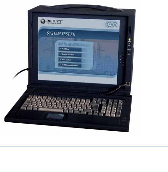
Figure 1-1 System Test Kit photograph
CAUTION: Tests conducted with the System Test Kit must be performed with the circuit breaker de-energized and racked-out to the test position. The test inputs will supersede the normal current and voltage inputs which disables normal protection, preventing response to fault conditions.
8 System Test Kit
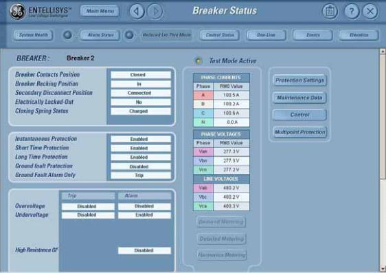
Figure 1-2 HMI screen showing circuit breaker in Test Mode
The HMI will indicate that the unit is in Test Mode. It will also display the output analog waveforms in response trip test.
Introduction 9
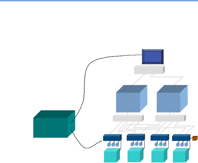
1.2 Test overview/architecture
The System Test Kit uses the method of low voltage injection to perform its tests. The test kit drives these low level voltages (10V p-p) into individual test inputs of the Messenger's A/D converter. Basic protection scheme, Functional protection, and Single Point Relay protection of the entire system can be tested using low voltage injection from the System Test Kit.
Figure 1-3 Entellisys system architecture with System Test Kit
U S B  H M I
H M I
S y s te m |
C o n fig u r a tio n |
D o w |
n lo a d L in k |
S y s t e m In t e r f a c e E t h e r n e t S w it c h
|
|
C P U |
A |
C P U B |
|
|
U S B |
M e s s e n g e r |
S w it c h |
M e s s e n g e r |
S w itc h |
|
|
S y s te m |
|
|
|
|
|
|
T e s t K it |
|
|
|
|
|
|
D B - 2 5 |
|
|
|
|
|
|
D B - 2 5 |
M e s s e n g e r |
M e s s e n g e r |
M e s s e n g e r |
M e s s e n g e r |
P T ’s |
|
|
C T C T C T |
|
C T C T C T |
C T C T C T |
C T C T C T |
|
T e s t C o n n e c to r |
|
|
|
|
|
|
|
B r e a k e r |
B r e a k e r |
B r e a k e r |
B r e a k e r |
|
|
10 System Test Kit

1.3 Test kit hardware/specs
All the digital signals given from the test kit and accepted from the test kit are active low TTL signals.
Table 1-1 Actual System Test Kit output accuracy
Sl.No |
Parameter |
Accuracy |
|
|
|
1. |
Voltage |
±0.1% |
|
|
|
2. |
Frequency |
±0.05 Hz |
|
|
|
3. |
Phase angle |
±0.1 |
|
|
|
4. |
Time Stamping |
±0.5 ms |
|
|
|
Required accuracy for protection testing is based on the accuracy of Entellisys System Accuracy.
Table 1-2 System accuracy with the test kit
Sl.No |
Protection |
Accuracy |
|
|
|
1. |
Current Protection 1X |
±6.5% |
|
|
|
2. |
Relay Protection |
±6.5% |
|
|
|
3. |
Ground Fault 0.2X |
±2% |
|
|
|
1.3.1 Test Unit PC
System Test Kit PC is a rugged Portable PC unit with multiple PCI slots. It uses two data acquisition cards to generate required test signals for injecting for testing protection elements in the Entellisys Low Voltage Switchgear system.
The test kit is entirely kiosked and runs on the Windows 2000 operating system.
1.3.2 Test kit power cord
The test kit power cord is designed with integrated surge protection equipment to protect the system from normal power anomalies.
Once the surge protector is triggered, it will be grounded (which can be detected by the surge protector; the LED will be ON). Once this occurs, the power cord will need to be replaced.
NOTE: The power cord must be replaced with the same cord to ensure proper operation.
Replacement Power Cord: GE CAT# ETSTESTKITCBLSRG
Test kit hardware/specs |
11 |
1.3.3 Test connector (System Test Kit to EntelliGuard Messenger cable)
The test connector is a 25-pin DB Type connector used for injecting signals to/from the Test Kit to the Messenger.
•Seven channels are analog outputs that represent three-phase voltages and currents plus a neutral. These –10V to +10V sinusoidal analog outputs are injected directly into a Messenger's A/D converter via the Messenger front panel. The test kit changes the waveform characteristics of these sinusoids to test the different protection schemes.
NOTE: If the cable is lost or broken, it must be replaced with the same cable to ensure proper operation.
Replacement “Test Connector” Cable: GE CAT# ETSTESTKITCBLMSR
1.3.4 USB-to-USB cable
The test kit communicates with the Entellisys Low Voltage HMI to download system configuration, preventing the operator from entering it manually.
A USB-to-USB cable, running a peer-to-peer network communication bridge, is used between the test kit and the HMI for communication. The USB-to-USB bridge arrives pre-configured in both the HMI and the test kit. See HMI setup on page 52 for configuration details.
To enable this communication, from the Test Kit Administration menu, enter the HMI IP address in the HMI Setup window.
NOTE: Special USB drivers for the cable supplied are preinstalled on the HMI. If the cable is lost or broken, it must be replaced with the same model.
Replacement USB to USB Cable: GE CAT# ETSTESTKITCBLUSB
12 System Test Kit
1.4 Getting started
1.4.1 Start up
Start the test kit by pushing the Power On button on the right-side panel.
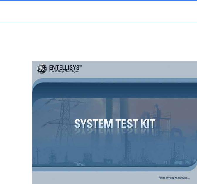
After the test kit boots, the following startup screen will be displayed:
Figure 1-4 Start Up screen
The System Test Kit is kiosked to prevent users from exiting the program and editing the system files and operating system. This provides added security to protect the system setup.
Press any key to continue.
Getting started |
13 |
1.4.2 Self Test
Each time the test kit is powered on, a Self Test is performed to verify the major components are functioning properly. The following tests are performed:
•Memory test – checks the physical memory in the system. At least 20 MB of free memory must be available after loading the application to ensure the system runs properly.
•Hardware configuration – checks the data acquisition card status. Two cards must be installed properly and have the proper device number.
•Test kit setup – checks the setup files and verifies the software and hardware version of the test kit.
•Ethernet connectivity – checks the Ethernet connectivity of the system to ensure the System Configuration Download Link (USB-to-USB Network Bridge) is working properly.
Figure 1-5 Self-Test screen
The test kit will display the test being performed on the screen. If any errors are encountered, the test kit will generate pop-up messages for the user regarding the type of error. Any issues must be corrected and the unit restarted before continuing. See Troubleshooting on page 59 for help diagnosing issues.
When the Self Test completes successfully, the Main Menu will be displayed.
14 System Test Kit
1.4.3 Main Menu
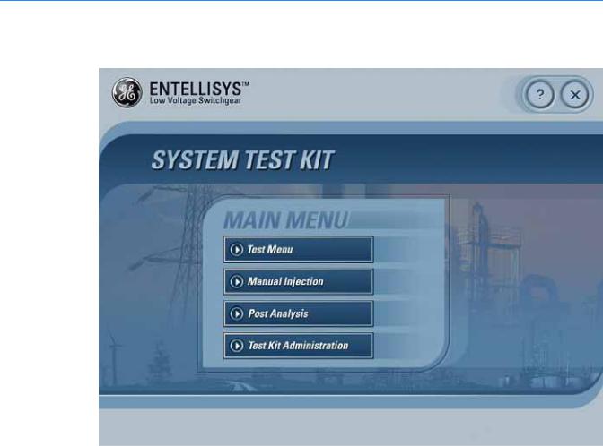
Figure 1-6 Main Menu screen
On the Main Menu, the following choices are provided:
Test Menu
This option lets the user download the settings either from the HMI or from the previously downloaded settings.
Manual Injection
The Manual Injection screen can be used to inject the signals by manually setting the test kit. The Manual Injection screen will pop out to accept the settings for the test kit.
Post Analysis
Provides access to the test kit log files for off-line analysis of the test results.
Test Kit Administration
This option allows the user to perform various tasks regarding the test kit setup.
Getting started |
15 |

1.4.4 General navigation
X Quit
Quit allows the user to quit from the application and shut down the system.
?Help
Clicking Help provides the user with help on the selected screen.
Tips
Moving the mouse cursor over the control provides tips for that control.
Short Cut Keys
Short cut keys are provided for the following controls:
F1 |
Pressing F1 will display help |
F4 |
Main Menu |
Ctrl F4 |
Back |
F10 |
Quit the application |
1.5 Download switchgear configuration
The test kit requires information about the switchgear lineup under test. For example:
•Circuit breakers by name, for ease of identification
•For each circuit breaker:
•Circuit breaker frame size, CT rating, and PT rating
•Rating switch setting
•Protection options enabled
•Protection elements Pickup and Delay Band Settings
This data provides the operator valid selections when selecting tests, and provides the proper output levels for the “Pre-Defined” Tests.
Once downloaded, this step can be avoided by using the “Last Download” information—so long as no configuration or settings have changed.
NOTE: To ensure the test kit has the correct configuration, download the configuration rather than using the “Last Download”.
16 System Test Kit

1.5.1 Direct Connect Download from HMI
Select this option to download the System Configuration from the HMI.
Before proceeding, connect the USB-to-USB cable between the HMI and the test kit. Figure 1-7 shows the USB port on the test kit. Note the white cable. Figure 1-8 shows the USB port on the HMI. Once the cable is connected, click OK to continue.
Figure 1-7 USB port on test kit
Download switchgear configuration |
17 |
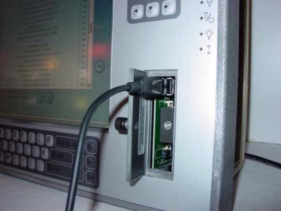
Figure 1-8 USB port on HMI
18 System Test Kit

Figure 1-9 shows the screens that will be encountered during the Direct Connect Download from HMI.
Figure 1-9 Switchgear configuration download process
Download errors will be displayed for the following reasons:
•Settings are not available
•Communications are not established
•Communication is lost
Download switchgear configuration |
19 |
1.5.1.1 System Configuration Download Link communication
The test kit communicates with the HMI over the System Configuration Download Link. This link is a USB-to-USB Network Bridge-Ethernet connection. The IP addresses are programmed by default into the test kit and the HMI and should not be changed. Download failure will result if these IP addresses are mismatched.
•Default HMI USB-to-USB Network Bridge IP address is 192.168.2.50.
•Default test kit USB-to-USB Network Bridge IP address is 192.168.2.25.
The HMI’s IP address must be set in the test kit. To verify this is set properly, from the HMI Setup screen, go to the Test Kit Administration.
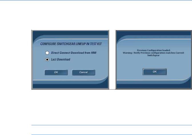
1.5.2 Last Download
Select this option to download the previously downloaded switchgear lineup configuration.
Figure 1-10 Process to download previous settings
Care should be taken before deciding to use previously downloaded settings.
•Is this the same lineup that was downloaded previously?
•Has anything changed since the configuration was downloaded previously?
NOTE: Mismatch in configuration and/or settings will result in incorrect test results.
20 System Test Kit
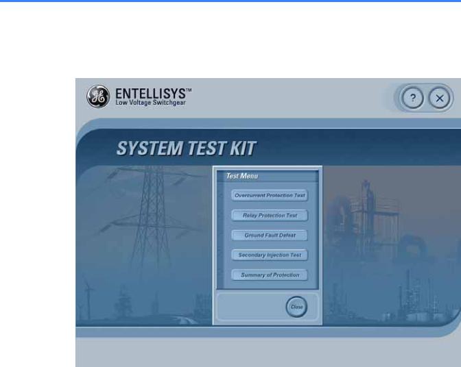
1.6 Test Menu
Once the switchgear configuration has been loaded, the Test Menu will display.
Figure 1-11 Test Menu
Below is a brief description of each of the tests:
Overcurrent Protection Test
Allows operator to perform Overcurrent Protection tests.
Relay Protection Test
Allows operators to perform Relay Protection tests.
Ground Fault Defeat
Allows operator to temporarily Defeat/Disable or Resume Ground Fault protection. This may be required for Primary or Secondary injection testing outside the test kit.
Secondary Injection Test
Allows operator to temporarily suspend CT Compensation for Secondary Injection testing outside the test kit.
Summary Of Protection
Provides the protection enabled at each circuit breaker.
Test Menu |
21 |
 Loading...