


g
INTRODUCTION
DEH–40026 Installation Instructions
ProTrip™ Conversion Kits
For GE Types AK-15, AK-25, and AKU25
Low-Voltage Power Circuit Breakers
GE Conversion Kits are designed for upgrading existing GE low-voltage power circuit breakers, rather than replacing the entire breaker. The Conversion Kits include ProTrip™ Trip Units, the latest technological advance in GE trip systems.
ProTrip Conversion Kits are designed and tested to conform to ANSI Standard C37.59, allowing the retrofitter to properly install the kit and acceptance test the breaker.
This publication covers installation of ProTrip Conversion Kits on GE types AK-15, AK-25, and AKU-25 low-voltage power circuit breakers. Each Conversion Kit contains all the components needed to convert from an existing GE trip system.
TABLE OF CONTENTS |
|
SECTION 1. GENERAL INFORMATION............................................................................................................ |
4 |
SECTION 2. BEFORE INSTALLATION.............................................................................................................. |
4 |
SECTION 3. FRONT-FRAME CONVERSION |
|
Separation of the Front and Back Frames.............................................................................................. |
5 |
Removal of the Existing Trip Device....................................................................................................... |
6 |
Remounting the X and Y Relays............................................................................................................. |
7 |
Installing the Flux Shifter......................................................................................................................... |
8 |
Installing the Trip Unit Bracket and Trip Unit ........................................................................................ |
10 |
SECTION 4. BACK-FRAME CONVERSION |
|
Current Sensor Installation ................................................................................................................... |
13 |
Stud Shield Modification ....................................................................................................................... |
15 |
Remounting Primary Disconnects ........................................................................................................ |
15 |
SECTION 5. CONFIGURING THE TRIP UNIT................................................................................................ |
16 |
SECTION 6. FOUR-WIRE GROUND FAULT OPTION ................................................................................ |
16 |
SECTION 7. TESTING AND TROUBLE-SHOOTING |
|
Testing .................................................................................................................................................. |
17 |
Trouble-Shooting................................................................................................................................... |
17 |
Nuisance Tripping on Ground Fault-Equipped Breakers......................................................... |
17 |
2
LIST OF FIGURES |
|
|
1. |
Arc chute retainer and arc chutes. ................................................................................................................... |
5 |
2. |
Screw to be removed from connecting links. ................................................................................................... |
5 |
3. |
Breaker bottom bracket connected to the escutcheon and the back frame .................................................... |
6 |
4. |
Type EC-2A trip device, with adjacent device removed................................................................................... |
6 |
5. |
Front view of the front frame, showing relocation of the X and Y relays.......................................................... |
7 |
6. |
Right side view of the front frame, showing relocation of the Y relay. ............................................................. |
8 |
7. |
Y relay installed on the arc chute retainer........................................................................................................ |
8 |
8. |
Unassembled flux shifter and mounting hardware........................................................................................... |
8 |
9. |
New flux shifter installed on the right side of the breaker mechanism (shown in the |
|
|
reassembled breaker). ..................................................................................................................................... |
9 |
10. |
Mounting and adjusting the flux shifter shown from the right side of the mechanism. .................................... |
9 |
11. |
Flux shifter as isntalled on the breaker. ........................................................................................................... |
9 |
12. |
Trip unit, mounting plate, support bracket, and harness................................................................................ |
10 |
13. |
Trip unit support bracket mounted to the breaker frame on a manually operated stationary |
|
|
breaker. .......................................................................................................................................................... |
10 |
14. |
Trip unit support bracket mounted to the breaker frame on an electrically operated draw-out |
|
|
breaker. .......................................................................................................................................................... |
10 |
15. |
Bottom view of the trip unit support bracket installed on an electrically operated breaker, |
|
|
showing the X relay and insulator. ................................................................................................................. |
11 |
16. |
Trip unit attached to the mounting plate......................................................................................................... |
11 |
17. |
Trip unit and mounting plate attached to the breaker. ................................................................................... |
12 |
18. |
Flux shifter wiring harness in place................................................................................................................ |
12 |
19. |
Components for the current sensor assembly for one pole........................................................................... |
13 |
20. |
Current sensor assembly, right-side view...................................................................................................... |
13 |
21. |
CT terminal board bracket and insulator installed.......................................................................................... |
13 |
22. |
Completed CT installation.. ............................................................................................................................ 13 |
|
23. |
Right-side view of the back frame, showing installation of the flux shifter actuator bushing......................... |
14 |
24. |
Modification of the lower stud shields. ........................................................................................................... |
15 |
25. |
Primary disconnect modification for AK-15 breakers..................................................................................... |
15 |
26. |
Neutral sensor outline .................................................................................................................................... |
16 |
27. |
Cabling diagram for PtoTrip™ trip units with ground fault on four-wire loads. .............................................. |
19 |
3

SECTION 1. GENERAL INFORMATION
GE Conversion Kit installation is straightforward, but does require careful workmanship and attention to these instructions. Familiarity with the breaker is highly desirable. Then general approach is to first remove the existing trip devices from the breaker, then install the ProTrip components. Following this procedure, the converted breaker is performance tested before it is returned to service.
The majority of trip unit kit installations do not require any customized assembly work. However, some installations may involve unusual mounting conditions or accessory combinations that require minor modifications and/or relocation of components. In most instances, this supplementary work can be done on site.
In preparation for the conversion, the installer should verify that the appropriate current sensors and trip unit have been furnished. Whenever a ProTrip kit is installed on a breaker with a four-wire system, an associated neutral sensor (CT) is required for separate mounting in the equipment. Ensure that retrofitted breakers are applied within their short-circuit ratings.
Note that all ProTrip trip units supplied with conversion kits are equipped with long-time, short-time, instantaneous, and defeatable ground fault (LSIGX) trip functions. The installer should be aware of how these functions will affect his application before installing the conversion kit.
As a service-related consideration, the installation of a ProTrip kit provides an excellent opportunity to perform normal maintenance on the breaker, particularly when the front and back frames are separated. Such procedures are described in the installation and maintenance manuals supplied with the breaker and equipment.
SECTION 2. BEFORE INSTALLATION
Before starting any work, turn off and lock out all power sources leading to the breaker, both primary and secondary. Remove the breaker to a clean, well-lighted work area.
WARNING: Low-voltage power circuit breakers use high-speed, stored-energy spring operating mechanisms. The breakers and their enclosures contain interlocks and safety features intended to provide safe, proper operating sequences. For maximum personnel protection during installation, operation, and maintenance of these breakers, the following procedures must be followed. Failure to follow these procedures may result in personal injury or property damage.
•Only qualified persons, as defined in the National Electrical Code, who are familiar with the installation and maintenance of low-voltage power circuit breakers and switchgear assemblies, should perform any work on these breakers.
•Completely read and understand all instructions before attempting any breaker installation, operation, maintenance, or modification.
•Turn off and lock out the power source feeding the breaker before attempting any installation, maintenance, or modification. Follow all lock-out and tag-out rules of the National Electrical Code and all other applicable codes.
•Do not work on a closed breaker or a breaker with the closing springs charged. Trip an OPEN breaker and be sure the stored-energy springs are discharged, thus removing the possibility that the breaker may trip OPEN or the closing springs discharge and cause injury.
•Trip the breaker OPEN, then remove the breaker to a well-lighted work area before beginning work.
•Do not perform any maintenance that includes breaker charging, closing, tripping, or any other function that could cause significant movement of a draw-out breaker while it is on the draw-out extension rails.
•Do not leave the breaker in an intermediate position in the switchgear compartment. Always leave it in the CONNECTED, TEST, or DISCONNECTED position. Failure to do so could lead to improper positioning of the breaker and flashback.
4
SECTION 3. FRONT-FRAME CONVERSION
Front-frame conversion consists of the following steps:
1.Separation of the front and back breaker frames.
2.Removal of the existing trip devices.
3.On electrically operated breakers with EC trip devices, relocating and remounting the X and Y relays.
3.Installation of the flux shifter and trip paddle.
4.Installation of the trip unit mounting bracket.
5.Installation of the trip unit wire harness.
Separation of the Front and Back Frames
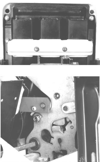
Figure 1. Arc chute retainer and arc chutes.
Use the following procedure to separate the front and back frames of the breaker.
1.Remove the breaker from its enclosure and place it on a suitable work surface.
2.Verify that closing springs are discharged and that the breaker is OPEN.
3.Loosen the two captive nuts and lift off the arc chute retainer, shown in Figure 1.
4.Lift the three arc chutes straight up and out of the breaker.
5.Remove the long screw and nut through the two connecting links on each side of the breaker, as shown in Figure 2.
6.Carefully place the breaker on its back surface, resting on the primary disconnects.
Figure 2. Screw to be removed from connecting links.
5

7.Remove the two mounting screws and lock washers attaching the bottom bracket to the escutcheon, as shown in Figure 3.
8.Loosen the recessed Allen screw in the side of the charging handle base and lift off the handle.
9.Remove the snap ring and flat washer on the charging handle mounting shaft.
10.Remove the four Philips-head screws and lock washers on the front of the escutcheon and lift off the escutcheon.
11.Lift the bottom bracket from its back frame attachment.
12.Remove the nuts and washers securing the front frame to the two long studs from the back frame.
13.Remove the nuts and washers on the studs connecting the front frame bracket to the back frame (one on each side).
14.Lift the front frame off the back frame.
Removal of the Existing Trip Device
Figure 4 shows an existing Type EC-2A trip device with the adjacent trip device already removed, to illustrate this procedure.
1.Remove the existing overcurrent trip devices and trip paddles.
2.On draw-out breakers, remove the primary disconnects from the bottom (load) copper studs.
3.Remove the three bottom (load) copper stud assemblies. On Power Sensor-equipped breakers, these will have been removed with the trip devices.
4.On breakers equipped with Type EC trip devices, remove and discard the mounting brackets on the lower front of the back frame.
Figure 3. Breaker bottom bracket connected to the escutcheon and the back frame.
Figure 4. Type EC-2A trip device, with adjacent device removed.
6
 Loading...