


DEH203 |
R02 |
g
EntelliGuard™ Power Circuit Breakers
800–2000 A Frames, 240–600 Vac
Maintenance Manual
DEH203
WARNINGS, CAUTIONS, AND NOTES
AS USED IN THIS PUBLICATION
WARNINGS
Warning notices are used in this publication to emphasize that hazardous voltages, currents, or other conditions that could cause personal injury are present in this equipment or may be associated with its use.
Warning notices are also used for situations in which inattention or lack of equipment knowledge could cause either personal injury or damage to equipment.
CAUTIONS
Caution notices are used for situations in which equipment might be damaged if care is not taken.
NOTES
Notes call attention to information that is especially significant to understanding and operating the equipment.
This document is based on information available at the time of its publication. While efforts have been made to ensure accuracy, the information contained herein does not cover all details or variations in hardware and software, nor does it provide for every possible contingency in connection with installation, operation, and maintenance. Features may be described herein that are not present in all hardware and software systems. GE Consumer & Industrial assumes no obligation of notice to holders of this document with respect to changes subsequently made.
GE Consumer & Industrial makes no representation or warranty, expressed, implied, or statutory, with respect to, and assumes no responsibility for the accuracy, completeness, sufficiency, or usefulness of the information contained herein. No warrantees of merchantability or fitness for purpose shall apply.
The following are trademarks of GE Company:
EntelliGuard™, EntelliGuard Messenger™, Entellisys™
© Copyright 2005 GE Company
All Rights Reserved
i

EntelliGuard™ 800–2000 A Power Circuit Breakers
Table of Contents
Chapter 1. Introduction |
|
|
1.1 |
Overview................................................................................................................................................... |
1 |
1.2 Inspection and Maintenance .................................................................................................................. |
1 |
|
1.3 |
Renewal Parts........................................................................................................................................... |
1 |
Chapter 2. Description |
|
|
2.1 |
Introduction ............................................................................................................................................ |
3 |
2.2 |
Frame Sizes .............................................................................................................................................. |
3 |
2.3 Operation ................................................................................................................................................ |
3 |
|
2.4 Fused Models ........................................................................................................................................... |
3 |
|
2.5 Mounting ................................................................................................................................................. |
3 |
|
2.6 |
Trip Units ................................................................................................................................................ |
3 |
2.7 |
Interruption Ratings ............................................................................................................................... |
3 |
Chapter 3. Storage, Safety, and Maintenance |
|
|
3.1 |
Storage ..................................................................................................................................................... |
5 |
3.2 |
Safety ........................................................................................................................................................ |
5 |
3.3 Maintenance............................................................................................................................................ |
5 |
|
Chapter 4. Breaker Operation |
|
|
4.1 |
Operating Instructions ............................................................................................................................ |
7 |
|
Sequence of Operations .................................................................................................................. |
7 |
|
Operation of the Breaker ................................................................................................................ |
7 |
|
Padlock Operation........................................................................................................................... |
8 |
4.2 |
Control Wiring ........................................................................................................................................ |
8 |
4.3 |
Breaker Interlocks ................................................................................................................................... |
8 |
|
Drawout Interlock............................................................................................................................ |
8 |
|
Contact Interlock ............................................................................................................................. |
8 |
|
Spring Discharge Interlock ............................................................................................................. |
8 |
4.4 |
Equipment Interlocks.............................................................................................................................. |
8 |
Chapter 5. Breaker Maintenance |
|
|
5.1 |
Lubrication ............................................................................................................................................ |
11 |
5.2 |
Removing and Reinstalling the Breaker .............................................................................................. |
11 |
|
Removing the Breaker................................................................................................................... |
11 |
|
Installing the Breaker .................................................................................................................... |
11 |
5.3 |
Slow Closing the Breaker ...................................................................................................................... |
13 |
5.4 Separation and Reconnection of Front and Back Frames................................................................... |
13 |
|
|
Separation of Front and Back Frames for EGS08, EGF08, and EGH08 ...................................... |
13 |
|
Reconnection of Front and Back Frames for EGS08, EGF08, and EGH08 ................................. |
14 |
|
Separation of Front and Back Frames for EGX08, EGS16, EGF16, EGH16, EGS20, and |
|
|
EGF20............................................................................................................................................. |
16 |
|
Reconnection of Front and Back Frames for EGX08, EGS16, EGF16, EGH16, EGS20, and |
|
|
EGF20............................................................................................................................................. |
16 |
|
ii |
|

EntelliGuard™ 800–2000 A Power Circuit Breakers |
|
Table of Contents |
|
5.5 Breaker Mechanism Operation and Adjustment ................................................................................. |
18 |
Trip Latch Adjustment .................................................................................................................. |
19 |
Chapter 6. Contact Maintenance |
|
6.1 Introduction .......................................................................................................................................... |
20 |
6.2 Arc Chute Removal and Replacement ................................................................................................. |
20 |
Arc Chutes in EGS08, EGF08, and EGH08 Breakers.................................................................... |
20 |
Arc Chutes in EGX08, EGS16, EGF16, EGH16, EGS20, and EGF20 Breakers ............................ |
20 |
6.3 Back Frame Assembly ............................................................................................................................ |
21 |
6.4 Replacement of Contacts ...................................................................................................................... |
21 |
Contact Replacement on EGS08, EGF08, and EGH08 Breakers ................................................. |
21 |
Contact Replacement on EGX08, EGS16, EGF16, EGH16, EGS20, and EGF20 Breakers.......... |
24 |
6.5 Adjusting the Contacts .......................................................................................................................... |
26 |
Contact Adjustment on EGS08, EGF08, and EGH08 Breakers .................................................... |
26 |
Contact Adjustment on EGX08, EGS16, EGF16, EGH16, EGS20, and EGF20 Breakers ............ |
26 |
Chapter 7. Maintenance of Standard Parts and Assemblies |
|
7.1 Primary Disconnects .............................................................................................................................. |
28 |
Primary Disconnect Replacement on EGS08, EGF08, and EGH08 Breakers.............................. |
28 |
Primary Disconnect Removal on EGX08, EGS16, EGF16, EGH16, EGS20, and EGF20 |
|
Breakers.......................................................................................................................................... |
28 |
Primary Disconnect Installation on EGX08, EGS16, EGF16, EGH16, EGS20, and EGF20 |
|
Breakers.......................................................................................................................................... |
29 |
7.2 Secondary Disconnect ........................................................................................................................... |
31 |
Secondary Disconnect Removal .................................................................................................... |
31 |
Secondary Disconnect Installation................................................................................................ |
31 |
7.3 Flux Shifter ............................................................................................................................................ |
32 |
Flux Shifter Adjustment................................................................................................................. |
32 |
Removing the Flux Shifter ............................................................................................................ |
32 |
Installing the Flux Shifter.............................................................................................................. |
32 |
7.4 Draw-Out Mechanism............................................................................................................................ |
34 |
Draw-Out Mechanism Removal .................................................................................................... |
34 |
Draw-Out Mechanism Installation ................................................................................................ |
34 |
Draw-Out Mechanism Adjustment................................................................................................ |
34 |
7.5 Escutcheon............................................................................................................................................. |
36 |
Escutcheon Removal ..................................................................................................................... |
36 |
Escutcheon Installation ................................................................................................................. |
36 |
7.6 Charging Handle................................................................................................................................... |
36 |
Removing the Charging Handle................................................................................................... |
36 |
Installing the Charging Handle .................................................................................................... |
36 |
Chapter 8. Accessory Maintenance |
|
8.1 Bell Alarm with Lockout........................................................................................................................ |
38 |
Removing the Bell Alarm with Lockout........................................................................................ |
38 |
Installing the Bell Alarm with Lockout ......................................................................................... |
39 |
8.2 Shunt Trip ............................................................................................................................................. |
39 |
iii |
|

EntelliGuard™ 800–2000 A Power Circuit Breakers |
|
Table of Contents |
|
Removing the Shunt Trip ............................................................................................................. |
40 |
Installing the Shunt Trip .............................................................................................................. |
40 |
8.3 Charging Motor..................................................................................................................................... |
41 |
Removing the Charging Motor..................................................................................................... |
41 |
Installing the Charging Motor ...................................................................................................... |
41 |
Removing the Motor Cut-Off Switch ............................................................................................ |
41 |
Installing the Motor Cut-Off Switch.............................................................................................. |
41 |
Adjusting the Motor Cut-Off Switch ............................................................................................. |
43 |
8.4 Remote Close ......................................................................................................................................... |
43 |
Removing the Remote Close ......................................................................................................... |
44 |
Installing the Remote Close .......................................................................................................... |
44 |
8.5 Open-Fuse Lockout ............................................................................................................................... |
45 |
Removing the Open-Fuse Lockout, 800 A and 1600 A Breakers.................................................. |
45 |
Installing the Open-Fuse Lockout, 800 A and 1600 A Breakers................................................... |
45 |
Removing the Open-Fuse Lockout, 2000 A Breakers ................................................................... |
45 |
Installing the Open-Fuse Lockout, 2000 A Breakers .................................................................... |
46 |
8.6 Remote Charge-Indication Switch........................................................................................................ |
47 |
Removing the Remote Charge-Indication Switch........................................................................ |
47 |
Installing the Remote Charge-Indication Switch ......................................................................... |
47 |
8.7 Network Interlock .................................................................................................................................. |
48 |
iv

EntelliGuard™ 800–2000 A Power Circuit Breakers
List of Figures
1. |
Front of the EntelliGuard circuit breaker, showing the locations of standard and optional |
|
|
features....................................................................................................................................................... |
2 |
2. |
Elementary diagram of the breaker control circuits. ............................................................................... |
9 |
3. |
Location of the secondary disconnect ...................................................................................................... |
9 |
4. |
Installing the breaker into the compartment......................................................................................... |
12 |
5. |
Disconnecting the closing spring assembly. ........................................................................................... |
13 |
6. |
Removing or installing the secondary disconnect ................................................................................. |
14 |
7. |
Movable contact connection to the breaker main shaft on EGS08, EGF08, and EGH08 breakers. ..... |
14 |
8. |
Separating the front and back frames on EGS08, EGF08, and EGH08 breakers.................................. |
15 |
9. |
Movable contact connection to the breaker main shaft on EGX08, EGS16, EGF16, EGH16, |
|
|
EGS20, and EGF20 breakers. .................................................................................................................. |
16 |
10. |
Separating the front and back frames on EGX08, EGS16, EGF16, EGH16, EGS20, and EGF20 |
|
|
breakers.................................................................................................................................................... |
17 |
11. |
Breaker mechanism in the CLOSED position. ...................................................................................... |
18 |
12. |
Breaker mechanism in the TRIPPED position. ..................................................................................... |
18 |
13. |
Breaker mechanism in the RESET position........................................................................................... |
18 |
14. |
Adjusting the trip latch. .......................................................................................................................... |
19 |
15. |
Typical back frame assembly, EGS08, EGF08, and EGH08. .................................................................. |
21 |
16. |
Typical back frame assembly, EGX08, EGS16, EGF16, EGH16, EGS20, and EGF20............................ |
21 |
17. |
Upper (stationary) contact assembly for EGS08, EGF08, and EGH08 breakers. .................................. |
22 |
18. |
Lower (movable) contact assembly for EGS08, EGF08, and EGH08 breakers...................................... |
22 |
19. |
Removal and installation of contact assemblies on EGS08, EGF08, and EGH08 breakers .................. |
23 |
20. |
Removal and installation of contact assemblies on EGX08, EGS16, EGF16, EGH16, EGS20, and |
|
|
EGF20 breakers........................................................................................................................................ |
25 |
21. |
Stationary main and intermediate contact styles. .................................................................................. |
25 |
22. |
Replacement of stationary arcing contacts............................................................................................. |
25 |
23. |
Contact adjustment on EGS08, EGF08, and EGH08 breakers............................................................... |
26 |
24. |
Contact adjustment on EGX08, EGS16, EGF16, EGH16, EGS20, EGF20 breakers. ............................. |
27 |
25. |
Primary disconnect assembly for EGS08, EGF08, and EGH08 breakers ............................................... |
28 |
26. |
Primary disconnect assembly for EGX08, EGS16, EGF16, EGH16, EGS20, and EGF20 breakers........ |
28 |
27. |
Primary disconnect removal and installation on EGS08, EGF08, and EGH08 breakers ...................... |
29 |
28. |
Primary disconnect removal and installation on EGX08, EGS16, EGF16, EGH16, EGS20, and |
|
|
EGF20 breakers........................................................................................................................................ |
30 |
29. |
Primary disconnect adjustment on EGX08, EGS16, EGF16, EGH16, EGS20 and EGF20 breakers. .... |
30 |
30. |
Secondary disconnect.............................................................................................................................. |
31 |
31. |
Secondary disconnect terminal numbering. .......................................................................................... |
31 |
32. |
Removing or installing the secondary disconnect. ................................................................................ |
31 |
33. |
Flux shifter ............................................................................................................................................... |
32 |
34. |
Flux shifter adjustment............................................................................................................................ |
32 |
35. |
Removal or installation of a flux shifter ................................................................................................. |
33 |
36. |
Draw-out racking mechanism. ................................................................................................................ |
34 |
|
v |
|

EntelliGuard™ 800–2000 A Power Circuit Breakers |
|
|
List of Figures |
|
|
37. |
Draw-out mechanism adjustment ............................................................................................................ |
34 |
38. |
Draw-out racking mechanism removal and installation......................................................................... |
35 |
39. |
Escutcheon kit and related parts. ............................................................................................................ |
36 |
40. |
Charging handle ...................................................................................................................................... |
37 |
41. |
Charging handle removal and installation. ............................................................................................ |
37 |
42. |
Charging handle mounting detail .......................................................................................................... |
37 |
43. |
Bell Alarm with Lockout connections on the secondary disconnect. .................................................... |
38 |
44. |
Bell Alarm with Lockout accessory kit. .................................................................................................... |
38 |
45. |
Bell Alarm with Lockout installation or removal. ................................................................................... |
38 |
46. |
Front view of the Bell Alarm with Lockout installation, showing the breaker mechanism tab |
|
|
engaging the mounting plate slot............................................................................................................ |
39 |
47. |
Orientation of the label on the Bell Alarm module for installation. ..................................................... |
39 |
48. |
Shunt Trip connections to the auxiliary switch and secondary disconnect. ......................................... |
40 |
49. |
Shunt Trip accessory kit........................................................................................................................... |
40 |
50. |
Shunt Trip module removal and installation. ........................................................................................ |
40 |
51. |
Charging Motor and cut-off switch.......................................................................................................... |
41 |
52. |
Removal and installation of the Charging Motor and cut-off switch..................................................... |
42 |
53. |
Cut-off switch adjustment......................................................................................................................... |
43 |
54. |
Remote Close accessory kit....................................................................................................................... |
43 |
55. |
Remote Close installation and removal................................................................................................... |
44 |
56. |
Open-Fuse Lockout accessory .................................................................................................................. |
45 |
57. |
Open-Fuse Lockout connections to the secondary disconnect for EGF-20 breakers. ............................ |
45 |
58. |
Open-Fuse Lockout installation and removal ......................................................................................... |
46 |
59. |
Remote charge-indication switch. ........................................................................................................... |
47 |
60. |
Remote charge-indication switch removal and installation. .................................................................. |
47 |
61. |
Remote charge-indication switch side view............................................................................................. |
47 |
62. |
Network Interlock connections to the secondary disconnect. ................................................................ |
48 |
63. |
Network Interlock assembly mounting to the circuit breaker bottom frame ......................................... |
49 |
64. |
Network Interlock module fastening to the mounting plate. ................................................................. |
49 |
65. |
Manual reset assembly mounting. ........................................................................................................... |
49 |
66. Trip paddle and set lever gap calibration ............................................................................................. |
49 |
|
vi

EntelliGuard™ 800–2000 A Power Circuit Breakers
List of Tables
1. |
Recommended service intervals, in number of ON-OFF operations, for EntelliGuard breakers. |
.......... 1 |
2. |
Breaker interruption ratings. .................................................................................................................... |
4 |
3. |
Sequence of operations that may be performed with the EntelliGuard circuit breaker......................... |
7 |
4. |
Secondary disconnect terminals with standard and optional connections. ......................................... |
10 |
5. |
Key to numbered parts in Figure 11, Figure 12, and Figure 13 ............................................................. |
18 |
6. |
Bell Alarm with Lockout wires and corresponding secondary disconnect terminals. .......................... |
39 |
7. |
Catalog number and operating voltage for the Shunt Trip accessory. ................................................. |
40 |
8. |
Catalog number and operating voltage for the Charging Motor accessory .......................................... |
41 |
9. |
Catalog number and operating voltage for the Remote Close accessory. ............................................. |
43 |
vii
EntelliGuard™ 800–2000 A Power Circuit Breakers
Chapter 1. Introduction
1.1 Overview
These instructions describe the procedures for maintenance and operation of EntelliGuard 800-2000 ampere low-voltage power circuit breakers. Figure 1 is a front view of the breaker, with key features indicated.
The proper use, care, and maintenance of these breakers is important both from the safety aspect of protecting personnel and for minimizing equipment damage when faults occur. Persons who apply, use, and service these breakers should be familiar with the information presented in this publication.
WARNING: Before inspecting or beginning any maintenance work on a circuit breaker, the breaker must be in the OPEN position and disconnected from all voltage sources, both power and control.
AVERTISSEMENT: Avant d’inspecter ou de débuter tout travail de maintenance d’un disjoncteur, celui-ci dout être en position OPEN et débranché de toutes les sources de voltage, à la fois de puissance et de contrôle.
Source of |
800 A Frame |
1600 and |
|
Recommendation |
2000 A Frames |
||
ANSI |
1750 |
500 |
|
EntelliGuard, no |
3500 |
1000 |
|
load |
|||
|
|
||
EntelliGuard, at |
2800 |
800 |
|
frame rating |
|||
|
|
Table 1. Recommended service intervals, in number of ON-OFF operations, for EntelliGuard breakers.
If a breaker is installed in an area of high humidity or a dusty atmosphere, it should be inspected more often. Monthly inspections might be warranted for a breaker operated under severe conditions.
Always inspect the breaker after it has interrupted a short circuit or ground fault.
A standard inspection should consist of the following steps:
1.Visual Check – Look for dirt, grease, or other foreign material on all breaker parts. Check insulating surfaces for conditions that could degrade insulating properties, such as cracks or evidence of overheating. Check for foreign objects on the bottom of the breaker compartment. Check for loose or damaged control wiring and for similar problems.
1.2 Inspection and Maintenance
Circuit breakers should be maintained under a systematic program. Take each breaker out of service periodically for inspection and maintenance to help establish high reliability in service. This policy is facilitated by keeping one or more spare breakers to install in place of breakers requiring maintenance. Keeping a stock of recommended renewal parts ensures that maintenance work can be done quickly.
The frequency at which an individual breaker should be inspected depends on the circumstances of its use. Table 1 lists the ANSI-recommended service interval with the GErecommended interval for EntelliGuard breakers. EntelliGuard breakers should be inspected after every short circuit interruption, after every number of ON-OFF operations given in Table 1, or every two years, whichever comes first. EntelliGuard breakers have been built and tested to operate reliably with inspections at twice the ANSI interval, thus saving time and money by reducing breaker downtime.
2.Operation – Observe a few close-open operations using the operating handle. If a breaker is seldom operated, such that it remains open or closed for six months or more, open and close the breaker several times in succession.
3.Interlocks – During the operational check, verify that the safety interlocks are working properly.
4.Arc Chutes and Contacts – Inspect the arc chutes and contacts for excessive burning or breakage. Check the amount of contact depression or wipe when the breaker is closed.
5.Accessories – Verify that the various accessories are working properly.
1.3Renewal Parts
Many of the parts and assemblies contained in EntelliGuard breakers are available as replacement parts. See DEF004 for a complete listing.
1

EntelliGuard™ 800–2000 A Power Circuit Breakers
Chapter 1. Introduction
G
H
J
A
B
C
D
E
F
K
Figure 1. Front of the EntelliGuard circuit breaker, showing the locations of standard and optional features.
A Indicator: DISC (white) TEST (white) CONN (white)
B Indicator: CHARGED (yellow)
DISCHARGED (white)
C Indicator: CLOSED (red) OPEN (green)
D CLOSE button (black)
EOPEN button (red)
FPadlock provision
GCatalog number, rating, and date code nameplate
HManual charging handle
JBell Alarm with Lockout target/RESET button
KDraw-out racking screw (behind cover)
2

EntelliGuard™ 800–2000 A Power Circuit Breakers
Chapter 2. Description
2.1 Introduction |
breaker, and a Shunt Trip to open the breaker. External |
|
EntelliGuard low-voltage power circuit breakers control |
control power is required to energize the motor and its |
|
control circuit. All breakers are equipped with a manual |
||
and protect power circuits up to 600 volts. They will safely |
charging handle so that the closing springs can be |
|
switch loads and automatically clear circuits during abnor- |
charged without motor control power. |
|
mal conditions when used with the EntelliGuard |
|
|
Messenger™. These include short circuits, sustained |
2.4 Fused Models |
|
overloads, and ground faults. |
||
EntelliGuard breakers contain a “quick-make, quick- |
Internally fused breakers are available in 800and 1600- |
|
break” mechanism, which stores energy in a closing spring |
||
ampere frame sizes. They are not interchangeable with |
||
for quick release. During closing, some energy is |
||
unfused breakers, since fused breakers require deeper |
||
transferred to an opening spring to be used subsequently |
||
compartments to accommodate the fuses. |
||
for fast tripping. |
||
|
||
The three main functional components of the breaker are |
2.5 Mounting |
|
its mechanism, an assembly consisting of the conductive |
||
components, and the interrupter. |
EntelliGuard breakers are designed for draw-out |
|
The mechanism is designed to receive energy, store it, and |
||
mounting. Draw-out breakers are easily installed into or |
||
later deliver it to close the breaker contacts. It must be able |
removed from their switchgear cubicle. They are |
|
to reverse the closing operation at any point upon receipt |
equipped with a racking mechanism, which is used to |
|
of a trip signal from the EntelliGuard Messenger (that is, |
insert or withdraw the breaker, and primary and |
|
it must be “trip-free”). Finally, it must also open a closed |
secondary disconnects, which connect and disconnect |
|
breaker quickly enough to minimize contact erosion and |
automatically. |
|
to effectively transfer the arc to the arc chutes. |
|
The current-carrying components are assembled on the back frame, which provides the required mechanical support and insulating structure. The conductive components are the studs for external connections, the movable and stationary contact sets, and the pivots for the movable contacts.
The interrupter components are the arcing contacts, the arc runners mounted on the back base, and the removable arc chute assemblies.
In addition to these basic components, a breaker may be equipped with a combination of accessories and interlocking devices.
2.2 Frame Sizes
The EntelliGuard breakers covered in this manual are available in 800-ampere, 1600-ampere, and 2000-ampere frame sizes. These values represent the maximum continuous-current rating of each frame. In addition, each breaker carries a specific rating that is determined by the current sensor ampere rating or the maximum setting of the EntelliGuard Messenger™ with which it is used.
2.6 EntelliGuard Messenger™
EntelliGuard low-voltage power circuit breakers are intended for use in Entellisys™ Low-Voltage Switchgear only. The breaker frames do not contain trip units or current transformers. Thus, the EntelliGuard circuit breaker must be used in concert with the EntelliGuard Messenger and the current transformers mounted within the switchgear cubicle. For installation and operation of the EntelliGuard Messenger, see DEH231 and DEH234.
2.7 Interruption Ratings
Table 2 lists the short-circuit current that each breaker type is rated to interrupt for each maximum rated voltage.
2.3 Operation
EntelliGuard breakers are available with either manual or electric operation. The mechanism closing springs of manually operated breakers are charged by operating the charging handle on the front of the breaker.
Electrically operated breakers contain an electric Charging Motor that charges the closing springs, a Remote Close accessory with antipump to close the
3

EntelliGuard™ 800–2000 A Power Circuit Breakers
Chapter 2. Description
Rated AC |
|
Short-Circuit RMS Symmetrical kA |
||
|
|
|
|
|
Voltage, |
|
|
|
|
Nominal |
Breaker |
Short-Time |
With |
Without |
(max) |
Type |
Withstand |
Inst. Trip |
Inst. Trip |
|
|
|
|
|
|
EGS-08 |
30 |
30 |
30 |
|
EGH-08 |
42 |
42 |
42 |
600 |
EGX-08 |
50 |
50 |
50 |
(635) |
EGS-16 |
42 |
42 |
42 |
|
EGH-16 |
65 |
65 |
65 |
|
EGS-20 |
65 |
65 |
65 |
|
EGS-08 |
30 |
30 |
30 |
|
EGH-08 |
42 |
42 |
42 |
480 |
EGX-08 |
65 |
65 |
65 |
(508) |
EGS-16 |
50 |
50 |
50 |
|
EGH-16 |
65 |
65 |
65 |
|
EGS-20 |
65 |
65 |
65 |
|
EGS-08 |
30 |
42 |
30 |
|
EGH-08 |
42 |
50 |
42 |
240 |
EGX-08 |
65 |
65 |
65 |
(254) |
EGS-16 |
50 |
65 |
50 |
|
EGH-16 |
65 |
65 |
65 |
|
EGS-20 |
65 |
65 |
65 |
Table 2. Breaker interruption ratings. (EGF-08/16/20 rated at 200kA).
4

EntelliGuard™ 800–2000 A Power Circuit Breakers
Chapter 3. Storage, Safety, and Maintenance
3.1 Storage |
|
|
associated personnel carefully apply a thorough |
||
The breaker should be put into service immediately in its |
understanding of the specific equipment with |
||||
regard to its purpose, its construction, its operation, |
|||||
permanent location. If this is not possible, the following |
and situations that could be dangerous. |
||||
precautions must be taken to ensure proper storage of the |
3. All personnel associated with installation, operation, |
||||
breaker |
|
|
|||
|
|
and maintenance of electrical equipment, such as |
|||
• Protect the breaker against condensation, preferably |
|||||
power circuit breakers and other power-handling |
|||||
by storing it in a warm, dry room, since water absorp- |
equipment, must be thoroughly instructed, with |
||||
tion has an adverse effect on the insulating parts. |
periodic retraining, about power equipment in gen- |
||||
• Store the breaker in a clean location free from corro- |
eral and the specific equipment with which they will |
||||
sive gases or fumes. It is particularly important to |
be working in particular. Instruction books, actual |
||||
protect the equipment from moisture and cement |
devices, and appropriate safety and maintenance |
||||
dust, as this combination is corrosive to many parts. |
procedures, such as OSHA publications, the |
||||
|
|
|
|
National Electrical Safety Code (ANSI C2), the |
|
|
CAUTION: If the breaker is stored for any |
|
National Electrical Code, and NFPA 7 OB Electrical |
||
|
length of time, inspect it periodically to ensure |
|
Equipment Maintenance, must be closely studied |
||
|
that steel parts have not begun to rust and to |
|
and followed. During actual work, supervisors |
||
|
ensure good mechanical condition. If the |
|
should audit procedures to ensure conformance. |
||
|
breaker has been stored under unfavorable |
|
4. Excellent maintenance is essential for reliability and |
||
|
atmospheric conditions, it must be cleaned and |
|
safety of all electrical equipment. Industry publica- |
||
|
dried before being placed in service. |
|
tions of recommended maintenance practices, such |
||
|
|
|
|
as ANSI/NFPA 70B, Electrical Equipment Maintenance, |
|
|
ATTENTION: Si le disjoncteur est remisé pour |
|
are readily available. |
||
|
peu importe la période de temps, inspectez-le |
|
|
||
|
périodiquement afin de vous assurer que les |
|
3.3 Maintenance |
||
|
pièces d’acier n’ont pas commencé à rouiller et |
|
|||
|
de vous assurer |
de leur bonne condition |
|
Both longand short-term maintenance of all electrical |
|
|
mécanique. Si le disjoncteur a été remisé à des |
|
|||
|
|
equipment is essential for reliability and safety. Mainte- |
|||
|
conditions atmosphériques défavorables, il doit |
|
|||
|
|
nance programs must be well-planned and carried out |
|||
|
être nettoyé et séché avant d’être mis en service. |
|
|||
|
|
consistently with both industry experience and the manu- |
|||
|
|
|
|
facturer’s recommendations. The local environment must |
|
3.2 Safety |
|
|
always be considered such programs, including such |
||
|
|
variables as ambient temperature, extreme moisture, |
|||
|
|
|
|
number of operations, corrosive atmosphere, significant |
|
Each facility must maintain a safety program for the pro- |
insect problems, and any other unusual or abusive condi- |
||||
tection of personnel, as well as other equipment, from the |
tion of the application. |
||||
hazards associated with electrical equipment. |
One of the critical service activities, sometimes neglected, |
||||
|
|
|
|
||
The following requirements are intended to augment a |
is the calibration of various control devices. These moni- |
||||
facility’s safety program, not |
to supplant local responsibil- |
tor conditions in the primary and secondary circuits, |
|||
ity for devising a complete safety program. The following |
sometimes initiating emergency corrective action, such as |
||||
basic industry-accepted safety requirements are applicable |
opening or closing circuit breakers. In view of the vital |
||||
to all major electrical equipment, such as switchgear and |
roles of these devices, it is important to follow a periodic |
||||
switchboards. General Electric neither condones nor |
test program. |
||||
assumes any responsibility for practices that deviate from |
General Electric recognizes that the interval between peri- |
||||
these requirements. |
|
|
|||
|
|
odic checks will vary, depending on the environment, the |
|||
1. All conductors must be assumed to be energized |
|||||
type of device, and the customer’s experience. GE recom- |
|||||
unless their potential has been measured as ground |
mends that, until the customer has accumulated sufficient |
||||
and suitable grounding conductors have been |
experience to select a test interval best suited to the local |
||||
applied to prevent energizing. Many accidents have |
requirements, all significant calibrations be checked at |
||||
been caused by back feeds from various sources. |
oneto two-year intervals. |
||||
2. Although interlocks are provided to reduce some of |
Operation and maintenance guides supplied by manufac- |
||||
the risks, each individual’s actions are essential to |
turers normally address components that require service |
||||
prevent accidents when performing service or main- |
or maintenance during the useful life of the equipment. |
||||
tenance. Each person’s knowledge, mental aware- |
However, they cannot include every possible part that |
||||
ness, and planned and executed actions often |
could require attention, particularly over a long service |
||||
determine if an accident will occur. The most |
period or under adverse conditions. Maintenance |
||||
important principle for avoiding accidents is that all |
personnel must be alert to deterioration of any part of the |
||||
|
|
|
|
5 |
|

EntelliGuard™ 800–2000 A Power Circuit Breakers
Chapter 3. Storage, Safety, and Maintenance
supplied switchgear, taking such action as necessary to restore it to serviceable status.
If additional assistance is required in the planning and performance of maintenance, contact GE Installation and Field Service (1-888-434SERV / 1-888-434-7378) to undertake the maintenance or to provide technical assistance, such as the latest publications.
The performance and safety of this equipment may be compromised by the modification or supplied parts or their replacement by non-identical substitutes. All such design changes must be qualified to ANSI/IEEE Standard C37.59.
Each customer should methodically keep written maintenance records as an aid in future service planning and equipment reliability improvement. Unusual experiences should be promptly reported to General Electric (1-888- GER-ESOLve).
6
EntelliGuard™ 800–2000 A Power Circuit Breakers
Chapter 4. Breaker Operation
4.1 Operating Instructions
Sequence of Operations
The sequence of operations that may be performed on the circuit breaker are listed in Table 3.
Closing the Breaker
Close the breaker contacts with any of the following methods:
•Depress the CLOSE button on the front of the breaker.
•Close the breaker using the Entellisys™ HMI.
Operation of the Breaker
Manually Charging the Closing Springs
Pull the operating handle down about 90° (until it stops) six times to fully charge the closing springs. This will not close the breaker contacts. The charge indicator will show CHARGED on a yellow background.
NOTE: The breaker cannot be closed unless the springs are fully charged and the handle is stored fully in.
NOTE: Le disjoncteur ne peut être fermé à moins que les ressorts ne soient pleinement chargés et que la poignée ne soit pleinement rentrée.
Electrically Charging the Closing Springs
If the breaker is equipped with the (optional) Charging Motor, the closing springs may also be charged with any the following methods:
•With the breaker in the TEST position, install the motor fuse in the fuse holder in the upper left corner of the breaker compartment.
•Operate the Charging Motor by applying the rated voltage to secondary disconnect terminals 8 and 17. Power to the motor is removed automatically by a cutoff switch when the springs are fully charged.
•If power is lost during the charging cycle, finish charging the springs by cycling the charging handle until the indicator shows CHARGED on a yellow background.
The closing springs will automatically recharge after closing if control power is maintained at terminals 8 and 17.
•Energize the (optional) Remote Close accessory by applying the rated voltage to secondary disconnect terminals 9 and 18.
If the breaker is closed electrically and the closing voltage is maintained, an antipump device prevents a second closing operation on the breaker in the event it is tripped OPEN. The closing impulse must be released for 1 to 2.5 seconds and reapplied before a second closing operation can occur.
If the closing voltage is applied while the closing springs are not fully charged, the Remote Close coil energizes, but operation of the closing mechanism is blocked. The closing voltage must be removed and reapplied when the springs are fully charged to close the breaker.
A mechanical interlock prevents the closing springs from discharging if an attempt is made to close an already CLOSED breaker.
NOTE: The main breaker contacts cannot be closed if any of the following conditions apply:
•The draw-out mechanism is in any position other than TEST or CONN, as displayed on the breaker position indicator.
•The (optional) Bell Alarm with Lockout was not reset after an overcurrent lockout.
•The (optional) Open Fuse Lockout was not reset after replacement of a blown fuse.
•The (optional) Network Interlock was not reset after a set operation.
These conditions must be corrected before the breaker can be closed. Attempts to close the breaker before these conditions are corrected may result in discharge of the closing springs without closing the main contacts.
Open/Closed |
Main Breaker |
Charge |
Condition of Close |
Next Permissible |
|
Indicator |
Contacts |
Indicator |
Springs |
Operating Function |
|
|
|
|
|
|
|
OPEN |
Open |
DISCHARGED |
Discharged |
Mechanism may be charged |
|
OPEN |
Open |
CHARGED |
Charged |
Contacts may be closed |
|
CLOSED |
Closed |
DISCHARGED |
Discharged |
Mechanism may be recharged or |
|
Contacts may be opened |
|||||
|
|
|
|
||
CLOSED |
Closed |
CHARGED |
Charged |
Contacts may be opened |
Table 3. Sequence of operations that may be performed with the EntelliGuard circuit breaker
7
EntelliGuard™ 800–2000 A Power Circuit Breakers
Chapter 4. Breaker Operation
NOTE: Les contacts principaux du disjoncteur ne peuvent être fermés si l’une ou l’autre des conditions suivantes s’appliquent:
•Le mécanisme de retrait du ressort est en tout autre position que: TEST ou DISC, tel que montré à la position indicatrice du disjoncteur.
•L’alarme optionnelle avec cloche n’a pas été remise en place après un blocage par surintensité de courant.
•Le mécanisme optionnel de déclenchement par sous voltage n’a pas été enclenché.
•Le verrouillage réciproque optionnel de réseaun'était pas réenclenché après une opération d'enclenchement.
Il faut que ces situations soient corrigées avant de procéder à la fermeture du disjoncteur.
Opening the Breaker
Open the breaker contacts with any of the following methods:
•Depress the OPEN button on the front of the breaker.
•Open or trip the breaker using the Entellisys™ HMI.
•Energize the (optional) Shunt Trip accessory by applying the rated voltage to secondary disconnect terminals 5 and 7.
Padlock Operation
The padlock provision prevents the breaker from closing by holding the trip latch in the tripped position. Up to three padlocks with 1/4" or 3/8" diameter shanks, or scis- sor-type safety lockout hasps may be inserted at one time. To install a padlock, use the following procedure:
WARNING: Be sure to test for proper operation of the mechanism, as described in step 1, before using it to secure the breaker.
AVERTISSEMENT: Assurez-vous de tester que le mécanisme opère correctement, tel que décrit à l'étape 1, avant de l'utiliser pour fixer le disjoncteur.
1.To check for proper installation of the padlock
mechanism, hold in the OPEN button, pull out the padlock slide, insert a 1/8" rod or #10 gage solid
wire, and attempt to close the breaker.
The breaker must not close.
2.While holding the OPEN button in, slide the padlock plate out and hold it in place.
3.Put the padlock or safety lockout hasp into one of the three holes in the padlock plate; this will
prevent the plate from returning to its unlocked position and prevent the breaker from closing.
4.2 Control Wiring
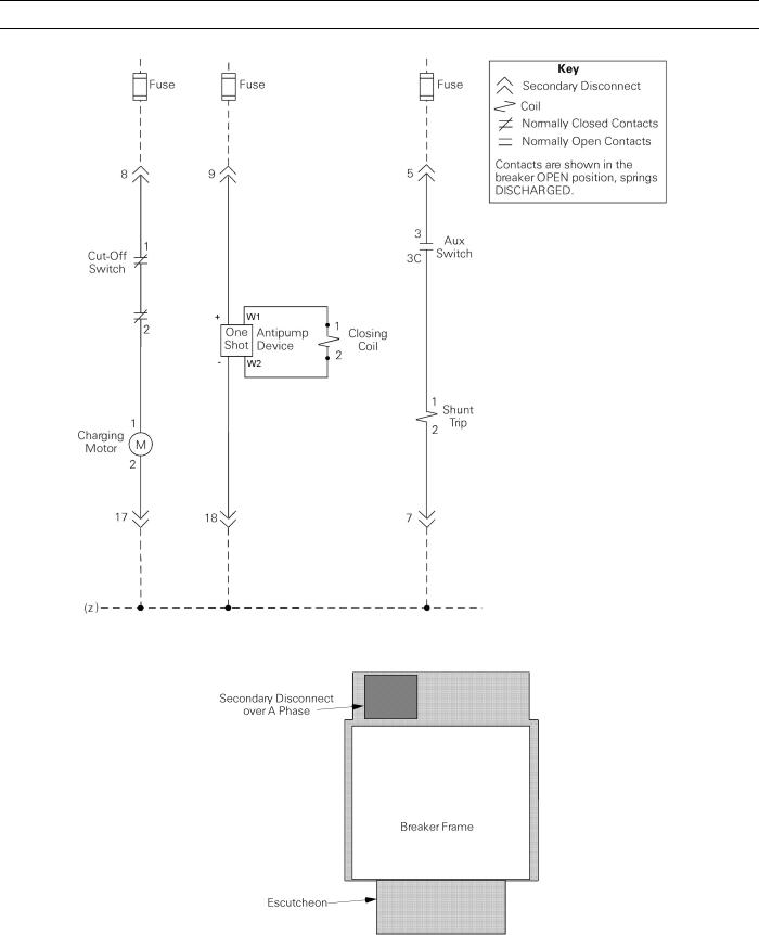
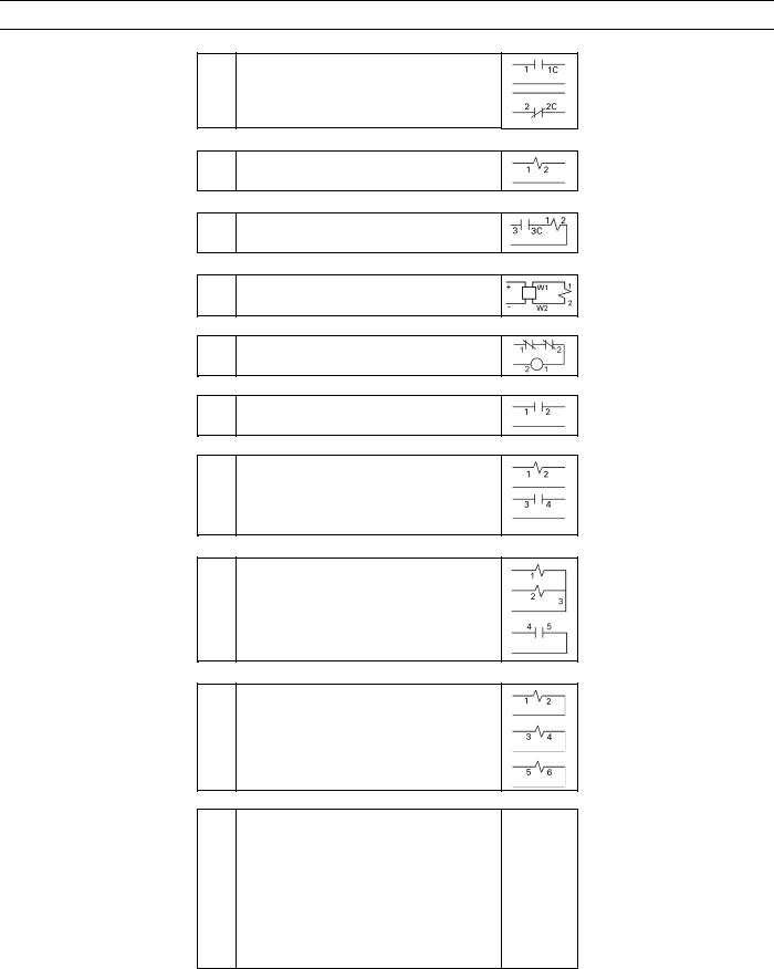
Figure 2 is the wiring diagram for the breaker control circuits. Table 4 lists the secondary disconnect terminals and the items connected to each. The location of the secondary disconnect is illustrated in Figure 3.
4.3 Breaker Interlocks
EntelliGuard breakers are equipped with a number of safety interlocks to prevent improper operation of the breaker.
Draw-Out Interlock
The draw-out interlock prevents the breaker from being closed when the breaker is in neither the CONN or TEST position, but is between these positions. A pin on the side of the breaker engages a ramped cam in the switchgear cubicle. When the pin is lifted 3/8" the breaker is held tripfree.
An additional interlock holds the breaker trip-free whenever the access door to the racking mechanism is open.
Contact Interlock
The contact interlock keeps the door to the draw-out mechanism racking screw closed whenever the breaker contacts are CLOSED. This prevents changes to the breaker’s position with the main contacts CLOSED.
Spring Discharge Interlock
The spring discharge interlock functions in conjunction with the circuit breaker’s draw-out interlock and a compartment-mounted cam to discharge the closing and opening springs before the breaker can be withdrawn from the compartment.
4.4 Equipment Interlocks
Additional optional interlocks may be furnished with the breaker enclosure. The Key Interlock prevents the breaker from closing when the interlock is engaged and requires one or more keys to operate. The Door Interlock prevents opening of the enclosure door when the breaker is in the CONN position. It can be defeated for authorized access. The door can be opened by racking the breaker to the TEST or DISC position.
8
EntelliGuard™ 800–2000 A Power Circuit Breakers
Chapter 4. Breaker Operation
Figure 2. Elementary diagram of the breaker control circuits.
Figure 3. Location of the secondary disconnect (top view of the breaker).
9
EntelliGuard™ 800–2000 A Power Circuit Breakers
Chapter 4. Breaker Operation
10Aux Switch (NO contact) 1 Aux Switch
2 Aux Switch
11Aux Switch (NC contact)
13 Flux Shifter
12 Flux Shifter common
5 Shunt Trip
7 Shunt Trip common
9 Close Circuit
18 Close Circuit common
8 Closing Spring Charging Motor
17 Closing Spring Charging Motor common
3Remote Charge Indicator
4Remote Charge Indicator
14 Bell Alarm Trip
6 Bell Alarm Trip Common
16 Bell Alarm Status
19Bell Alarm Status Comon OR
15Network Interlock SET
20Network Interlock RESET
21Network Interlock SET/RESET common
16Network Interlock Status
19 Network Interlock Status common
22OFLO (phase A)
23OFLO (phase A)
24OFLO (phase B)
25OFLO (phase B)
26OFLO (phase C)
27OFLO (phase C)
28Spare
29Spare
30Spare
31Spare
32Spare
33Spare
34Spare
35Spare
36Spare
Table 4. Secondary disconnect terminals with standard and optional connections.
10
 Loading...