


 Loading...
Pulsar Plus Controller Family
Product Manual
Product Manual
CC848815341
Issue 7
December 2011
Notice:
The information, specifications, and procedures in this manual are subject to change without notice. Lineage Power assumes no responsibility for any errors that may appear in this document.
© 2011 Lineage Power
All International Rights Reserved
Printed in U.S.A.

Pulsar Plus Controller Family
Table of Contents |
|
Table of Contents.................................................................................................................. |
3 |
Table of Figures .................................................................................................................... |
5 |
Table of Tables...................................................................................................................... |
6 |
Introduction ......................................................................................................................... |
9 |
Pulsar Plus Family Controllers .................................................................................................... |
9 |
Key Features ............................................................................................................................... |
9 |
Applications .............................................................................................................................. |
11 |
Product Description ............................................................................................................ |
13 |
Overview................................................................................................................................... |
13 |
Configurations .......................................................................................................................... |
14 |
Getting Started – Installation, Start-Up, and Basic Configuration .......................................... |
17 |
Preparation............................................................................................................................... |
17 |
Install and Configure Slot/Door-Mount Controllers................................................................. |
18 |
Install and Configure Pulsar Plus NE843G Controller ............................................................... |
23 |
Connect To the Controller ........................................................................................................ |
29 |
Initial Startup of the Controller ................................................................................................ |
43 |
Basic Controller Configuration.................................................................................................. |
44 |
Web Interface........................................................................................................................... |
47 |
Controller Operation........................................................................................................... |
53 |
Overview................................................................................................................................... |
53 |
Front Panel Controls and Status Display - Pulsar ..................................................................... |
54 |
Front Panel Controls and Status Display - Phoenix .................................................................. |
57 |
Audible Alarm ........................................................................................................................... |
60 |
Voltage Test Jacks..................................................................................................................... |
61 |
Local and Remote Access Ports ................................................................................................ |
62 |
Front Panel Menu Structure ..................................................................................................... |
63 |
Status ........................................................................................................................................ |
70 |
Control/Operations .................................................................................................................. |
74 |
History ...................................................................................................................................... |
76 |
Configuration............................................................................................................................ |
77 |
10/100 Base-T Port................................................................................................................... |
89 |
Optional Devices and Modules ............................................................................................ |
93 |
One-Wire Peripheral Devices ................................................................................................... |
93 |
NE872A Distribution Monitor and Control Module ............................................................... |
100 |
QS871A Distribution Monitor and Control Module ............................................................... |
105 |
ES772A Remote Distribution Module..................................................................................... |
109 |
Troubleshooting ............................................................................................................... |
119 |
Specifications.................................................................................................................... |
123 |
Safety ............................................................................................................................... |
127 |
Safety Statements................................................................................................................... |
127 |
Warning Statements and Safety Symbols .............................................................................. |
128 |
Precautions............................................................................................................................. |
129 |
Contacts and Warranty ..................................................................................................... |
131 |
Customer Service Contacts..................................................................................................... |
131 |
Product Warranty ................................................................................................................... |
131 |
Appendix A: Software Upgrades through Craft Port ........................................................... |
133 |
Appendix B: T1.317 Command Language ........................................................................... |
139 |
Issue 7 December 2011 |
3 |

Pulsar Plus Controller Family
Initializing Controllers ............................................................................................................. |
139 |
T1.317 Command Language.................................................................................................... |
140 |
Appendix C: Battery Functions........................................................................................... |
163 |
Float Mode .............................................................................................................................. |
163 |
Slope Thermal Compensation ................................................................................................. |
163 |
Plant Battery Test.................................................................................................................... |
166 |
Boost Mode............................................................................................................................. |
167 |
Appendix D: Default Configurations................................................................................... |
171 |
Appendix E: Alarms and Relays.......................................................................................... |
185 |
Alarm Relays............................................................................................................................ |
185 |
Alarms ..................................................................................................................................... |
185 |
Appendix F: SNMP ............................................................................................................ |
191 |
Issue History ..................................................................................................................... |
195 |
Issue 7 December 2011 |
4 |

Pulsar Plus Controller Family
Table of Figures |
|
Figure 1: Infinity NE and P2 Power Systems ............................................................................................... |
11 |
Figure 2: Compact Power Systems.............................................................................................................. |
12 |
Figure 3: General Power System Block Diagram......................................................................................... |
13 |
Figure 4: Generic Block Diagram of Pulsar Plus NE843A Controller ........................................................... |
14 |
Figure 5: Front Panel Display ...................................................................................................................... |
53 |
Figure 6: front Panel - Pulsar....................................................................................................................... |
54 |
Figure 7: Front Panel - Phoenix III............................................................................................................... |
57 |
Figure 8: Status Menu................................................................................................................................. |
66 |
Figure 9: Control / Operations and History Menus..................................................................................... |
67 |
Figure 10: Configuration Menu (part 1)...................................................................................................... |
68 |
Figure 11: Configuration Menu (part 2)...................................................................................................... |
69 |
Figure 12: QS873A Voltage/Thermal Probe (VT-Probe) ............................................................................. |
93 |
Figure 13: VT-Probe Connections To Infinity NE......................................................................................... |
94 |
Figure 14: ES771A Remote Voltage Monitor Module................................................................................. |
96 |
Figure 15: Four-String System Monitored For Imbalance With One VT Probe Per String.......................... |
98 |
Figure 16: Same System Monitored For Imbalance With VT Probe On Every Battery ............................... |
99 |
Figure 17: NE872A Remote Distribution Module ..................................................................................... |
101 |
Figure 18: NE872A ID Jumper Settings ..................................................................................................... |
103 |
Figure 19: NE872A ID Jumper Settings ..................................................................................................... |
103 |
Figure 20: QS871A Remote Distribution Module ..................................................................................... |
105 |
Figure 21: ES772A Remote Distribution Module ...................................................................................... |
109 |
Figure 22: Typical Alarm Connections....................................................................................................... |
112 |
Figure 23: Alarm Connections with Reverse Polarity Protection.............................................................. |
113 |
Figure 24: Reverse Polarity Protected Alarm Connections with an External Battery Disconnect Switch114 |
|
Figure 25: Alarm Connections for DIN Style Load Protectors................................................................... |
115 |
Figure 26: ES772A Mounting Hole Locations............................................................................................ |
116 |
Figure 27: J5694722 External Distribution................................................................................................ |
116 |
Issue 7 December 2011 |
5 |

Pulsar Plus Controller Family
Table of Tables |
|
Table 1 Pulsar Plus Controller Family Product Options |
.............................................................................. 16 |
Table 2 Controller Standard Defaults Door Mounted ................................................................................ |
21 |
Table 3 Table 2 Controller Standard Defaults NE843G .............................................................................. |
27 |
Table 4 Auxiliary Input Connector.............................................................................................................. |
32 |
Table 5 Output Alarm Connector ............................................................................................................... |
34 |
Table 6 Local RS-232 Serial Port Signals ..................................................................................................... |
37 |
Table 7 Power And Sense Connector ......................................................................................................... |
38 |
Table 8 Status LEDs - Pulsar........................................................................................................................ |
56 |
Table 9 Status LEDs - Dedicated - Phoenix ................................................................................................. |
58 |
Table 10 Status LEDs - Custom Assignable - Phoenix ................................................................................. |
58 |
Table 11 Rectifier Status............................................................................................................................. |
70 |
Table 12 Converter Status .......................................................................................................................... |
70 |
Table 13 Batteries Status............................................................................................................................ |
71 |
Table 14 Shunt Currents Status .................................................................................................................. |
71 |
Table 15 Disconnect States Status.............................................................................................................. |
71 |
Table 16 Alarm Thresholds Status .............................................................................................................. |
72 |
Table 17 Enabled/Disabled Info Status ...................................................................................................... |
72 |
Table 18 Network Settings Status .............................................................................................................. |
73 |
Table 19 System Info Status ....................................................................................................................... |
74 |
Table 20 Control/Operations...................................................................................................................... |
74 |
Table 21 History.......................................................................................................................................... |
76 |
Table 22 Float Settings Configuration ........................................................................................................ |
77 |
Table 23 Shunt Monitors Configuration..................................................................................................... |
78 |
Table 24 Shunt Type Configuration ............................................................................................................ |
79 |
Table 25 Rectifiers Configuration ............................................................................................................... |
81 |
Table 26 Batteries Configuration................................................................................................................ |
82 |
Table 27 Contactors Configuration............................................................................................................. |
84 |
Table 28 Disconnects Configuration........................................................................................................... |
84 |
Table 29 Converters Configuration ............................................................................................................ |
85 |
Table 30 Boost Configuration..................................................................................................................... |
86 |
Table 31 System Settings Configuration..................................................................................................... |
88 |
Table 32 Communication Ports Configuration ........................................................................................... |
88 |
Table 33 NE872 J1 Signal Description....................................................................................................... |
103 |
Table 34 NE872 J2 Signal Description....................................................................................................... |
104 |
Table 35 NE872 TB1 Signal Description.................................................................................................... |
104 |
Table 36 NE872 J100 and J101 Signal Description ................................................................................... |
105 |
Table 37 QS871 J1 Signal Description....................................................................................................... |
107 |
Table 38 QS871 J2 Signal Description....................................................................................................... |
108 |
Table 39 QS871 J3 Signal Description....................................................................................................... |
108 |
Table 40 QS871 J100 and J101 Signal Description ................................................................................... |
108 |
Table 41 ES772 Connector J1 Pinout Definitions ..................................................................................... |
112 |
Table 42 ES772 Connector J3 Pin Definitions ........................................................................................... |
112 |
Table 43 Auxiliary Port Connector Signals................................................................................................ |
115 |
Table 44 Infinity NE System Troubleshooting .......................................................................................... |
119 |
Table 45 Specifications ............................................................................................................................. |
123 |
Table 46 T1.317 Power System Related Commands................................................................................ |
140 |
Table 47 T1.317 User Login Related commands ...................................................................................... |
142 |
Issue 7 December 2011 |
6 |

Pulsar Plus Controller Family
Table 48 T1.317 DC Plant Related Commands.......................................................................................... |
142 |
Table 49 T1.317 Alarms With Two Thresholds Related Command .......................................................... |
142 |
Table 50 T1.317 Alarms With One Threshold Related Command ............................................................ |
143 |
Table 51 T1.317 Alarms With No Threshold Related Command .............................................................. |
144 |
Table 52 T1.317 Rectifier Management Related Commands ................................................................... |
145 |
Table 53 T1.317 Rectifiers Related Commands ........................................................................................ |
145 |
Table 54 T1.317 Converter Plant Related Commands.............................................................................. |
146 |
Table 55 T1.317 DC Converter Related Commands.................................................................................. |
147 |
Table 56 T1.317 Battery Reserve Management Related Commands ....................................................... |
147 |
Table 57 T1.317 Battery Type Definition Related Commands.................................................................. |
148 |
Table 58 T1.317 Boost Management Related Commands ....................................................................... |
148 |
Table 59 T1.317 Disconnect Contactor Control Related Commands........................................................ |
148 |
Table 60 T1.317 Distribution Current Monitor Related Commands......................................................... |
149 |
Table 61 T1.317 Distribution Contactor Interface Related Commands.................................................... |
149 |
Table 62 T1.317 Slope Thermal Compensation Related Commands........................................................ |
149 |
Table 63 T1.317 Input Management Related Commands ........................................................................ |
150 |
Table 64 T1.317 Call-Out Manager Related Commands........................................................................... |
150 |
Table 65 T1.317 Call-Out Phone Number Related Commands................................................................. |
151 |
Table 66 T1.317 Call-Out Email Address Related Commands................................................................... |
151 |
Table 67 T1.317 SNMP Destination Related Commands.......................................................................... |
151 |
Table 68 T1.317 Periodic Call-Out Related Commands ............................................................................ |
151 |
Table 69 T1.317 Modem Related Commands........................................................................................... |
151 |
Table 70 T1.317 Local RS-232 Port Related Commands ........................................................................... |
152 |
Table 71 T1.317 Alarm Test Related Commands...................................................................................... |
152 |
Table 72 T1.317 Alarm Cut-off Related Commands ................................................................................. |
153 |
Table 73 T1.317 User Defined Events Related Commands....................................................................... |
153 |
Table 74 T1.317 Derived Channels Related Commands ........................................................................... |
153 |
Table 75 T1.317 Trend Related Commands.............................................................................................. |
154 |
Table 76 T1.317 TL1 Manager Related commands................................................................................... |
154 |
Table 77 T1.317 TL1 Object Related Commands ...................................................................................... |
154 |
Table 78 T1.317 Call-Back Security Related Commands........................................................................... |
154 |
Table 79 T1.317 Mid-String Voltage Related Commands ......................................................................... |
154 |
Table 80 T1.317 Network Settings Related Commands............................................................................ |
155 |
Table 81 T1.317 Auxiliary Network Settings Related Commands............................................................. |
155 |
Table C-1 Supported Battery Types .......................................................................................................... |
169 |
Table D-1 Standard Configuration Item Defaults...................................................................................... |
172 |
Table D-2 24V Battery Related Items Defaults ......................................................................................... |
183 |
Table D-3 48V Battery Related Items Defaults ......................................................................................... |
184 |
Issue 7 December 2011 |
7 |

Pulsar Plus Controller Family
This page is intentionally blank.
Issue 7 December 2011 |
8 |

Pulsar Plus Controller Family
Introduction
Pulsar Plus Family Controllers
Overview
The Pulsar Plus family of controllers is comprised of the Pulsar Plus, Pulsar Edge, and Phoenix controllers. This manual covers the Pulsar Plus and Phoenix controllers.
These controllers were developed for both indoor and outdoor cabinet power applications.
Modular hardware and software design of the controllers allow for easy customization for specific applications.
Controllers provide control and alarm monitoring functions over several communication interfaces including a standard RS-485 digital serial interface that interconnects system rectifiers, converters, and other peripherals. Compatible rectifiers include NE, CP, NP, EP, IP, and 59X series.
Local and remote access is provided.
Features are factory configured to industry standard defaults to minimize the setup process in the field. Customer specified factory default configuration is also available.
Key Features
•Modular design allows different packaging alternatives: a single power slot positions of the rectifier shelf, mounting to a cabinet or distribution door, and 1U rack-mount option
•Easily field replaceable
•Standard or customer specific factory defaults supported
•Support of more than one factory default
•Supports dual voltage plants, with rectifiers and converters
•Auto-sensing dual voltage (both voltages and both currents displayed on front panel)
•Power Unit control and management
•Centralized settings for converter and rectifier output set-point voltages.
•Up to 60 NE power modules (Rectifiers and converters)
•Up to 32 CP rectifiers
•Extensive Battery Management features
•Management of four independent Low Voltage Disconnects (LVDs)
Up to eight contactors can be assigned to contactor interface IDs
Load disconnects operated by low voltage, low voltage and/or time delay, remote command, or external control signal
Battery disconnect operated by voltage threshold, voltage threshold and/or time, remote command, high battery temperature, or Emergency Power Off (EPO) signal
•Battery recharge current limit feature
•Low and high temperature voltage compensation
Independent adjustable slopes
Issue 7 December 2011 |
9 |

Pulsar Plus Controller Family
Step function
•Manual and automatic Boost charging
•Manual, remote test, and periodic discharge test capability
Reserve time calculations with configurable threshold
Manual time threshold for pass/fail criteria
•1-Wire monitoring
Up to six ES771 Mid-string voltage monitors (configurable mid-string imbalance alarm)
Up to sixteen battery thermal probes (configurable temperature alarm)
•Alarm management of 24V and 48V DC distribution
•User defined thresholds
•Front accessible 64x128 LCD with control pad and intuitive menu navigation system
•Available front panel PIN (password) access feature
•Alarm severity sensitive display back-light (LEDs on Phoenix controllers)
•Voltage Test Jacks for both DC busses
•Three separate configurable assignable LED indicators (18 on Phoenix controllers)
•Built-in audible alarm and test feature
•10 configurable alarm outputs with manual alarm test features
•10 configurable binary inputs
•Integrated 10/100Base-T Ethernet for local port or for Network remote monitoring
•SNMP, TCP/IP, SMTP, HTTP, Telnet, FTP, and utilizes Dynamic Host Configuration Protocol (DHCP)
•Compatible with standard browsers (MS Internet Explorer)
•Event history log
•Rectifier Group Standby/ Hold-off mapping (generator/AC load minimization)
Issue 7 December 2011 |
10 |
Pulsar Plus Controller Family
Applications
The Pulsar Plus controller family has applications in Infinity NE, Infinity P2, the Compact Power (CP) Line, EPS, and previous generation power systems. Following are product depictions utilizing the various configurations of the controller. These applications utilize the NE843A slot controller and the NE843C, NE843E, and NE843P door/panel mounted controllers. Consult appropriate system manuals, technical field support or your local sales representative for more details on these or other power systems.
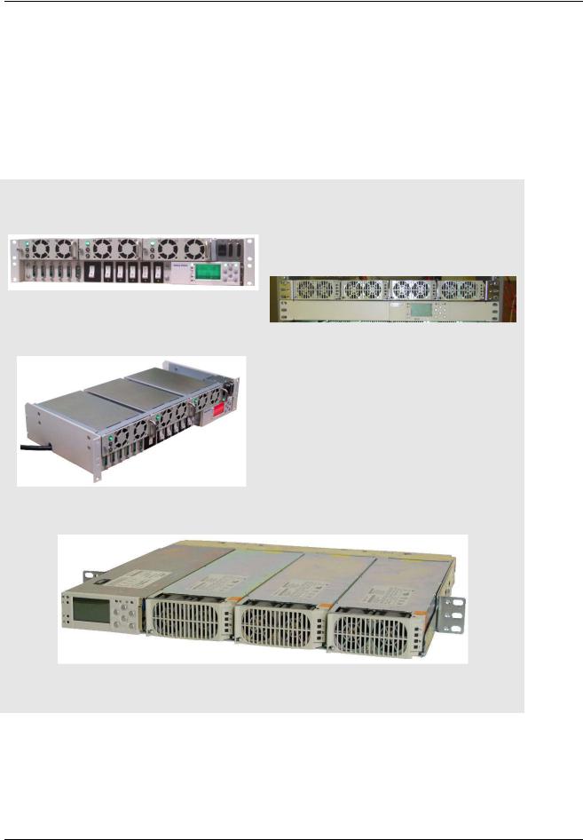
Infinity NE and P2 Systems
Infinity NE-M Selectable Power System |
Infinity NE-S Power System |
(Pulsar Plus NE843E) |
(Pulsar Plus NE843E) |
Infinity NE-D Distributed Power System |
Infinity P2 Power System |
(Pulsar Plus NE843E) |
(Phoenix NE843P) |
Figure 1: Infinity NE and P2 Power Systems
Issue 7 December 2011 |
11 |
Pulsar Plus Controller Family
The Pulsar Plus NE843A slot controller is inserted into the left-most position of the rectifier shelf. This position in the shelf allows access to all I/O. The panel/door-mounted Pulsar Plus NE843C/NE843E/NE843P controllers are typically installed at the factory, but can also be ordered separately for spares or integrated into custom systems.
The following pictures depict the Pulsar Plus controller in the EPS and Compact Power systems. These include two slot controllers, EP843D and the CP843A, and the 1U rack-mount controller applicable in 19” and 23” frames. The Pulsar Plus controllers provide a front panel DB9 or RJ45 Craft port for local terminal access using RS-232. A front panel position is reserved for a second RJ45 Ethernet connection in the near future.
Compact Power Systems
EPS2400 Power System
(Pulsar Plus EP843D)
Compact Power Shelf
(Pulsar Plus NE843G)
Compact Power Shelf
(Pulsar Plus CP843A)
Figure 2: Compact Power Systems
Issue 7 December 2011 |
12 |
Pulsar Plus Controller Family
Product Description
Overview
Introduction
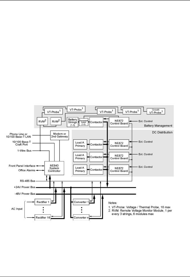
Lineage Power System rectifiers accept alternating current (ac) power and rectify it to produce direct current (dc) power for powering external equipment (loads). Converters accept the dc output from rectifiers or other sources and convert it to various regulated output dc levels also needed for powering external equipment (loads). Batteries, generators, and UPS are used to provide backup power when ac is lost. When batteries are used, they are connected in parallel for additional capacity along with the rectifier outputs through appropriate breakers and contactor disconnects. DC power is distributed through distribution panels with various protectors and contactors. These rectifiers, converters, backup systems, and distribution are all managed by the controller. The following figure depicts a generic representation of the system controller and its relationship in a power system. The components depicted and their associated features as they relate to the system controller will be discussed in this manual.
Figure 3: General Power System Block Diagram
Issue 7 December 2011 |
13 |
Pulsar Plus Controller Family
Configurations
The main “843” microprocessor board comprises the Pulsar Plus family controllers. These controllers are designed to fit a variety of systems and applications. Input and output wiring is connectorized to allow swift disconnect and attachment to and from the unit. There are several different configuration options for the controllers. The “843” board is designed to fit in NE and CP power slots can be quickly installed or removed entirely from a power position with the use of an integrated latch. Controllers can also be ordered as a direct door or panel mount controller. Within these different physical configurations there are available integrated options that include items such as a modem or a second Ethernet port. For slot controllers, these options must be ordered and pre-installed at the factory. Options for door/panel mount controllers can be added in the field.
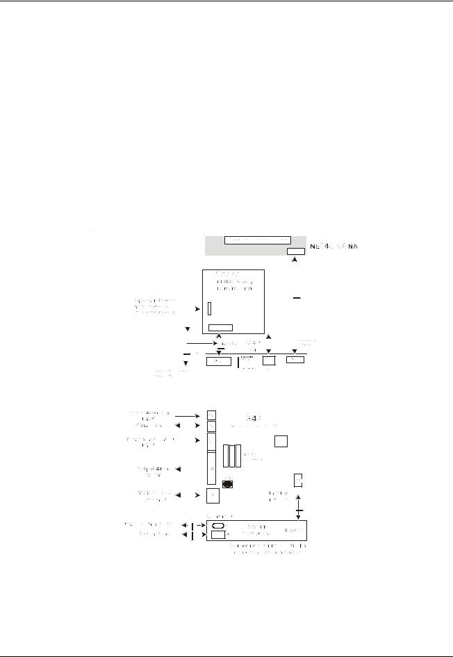
The following figure is a block diagram of the basic components of the Pulsar Plus NE843A slot controller. Controller options that mount directly to a door or panel do not require the small internal connection board used to interface with the backplane. As an example, the NE843_CONA shown below is the interconnect board used in the Pulsar Plus NE843A slot controller for interfacing to the NE shelf’s backplane.
Figure 4: Generic Block Diagram of Pulsar Plus NE843A Controller
Issue 7 December 2011 |
14 |

Pulsar Plus Controller Family
A listing of the controller options is defined in this section. A brief description is provided for each configuration. These are the basic configurations that are available from the factory. Always consult the controller ordering guide (PULSAR-AD) and respective sales contacts to ensure the most complete and up to date listing. The naming convention used for the Pulsar Plus product family and its options are factory orderable is:
ZZ 843 A D - XXX - YYY
Where;
ZZThis identifies the product family of Pulsar Plus 843 controller. (Valid IDs are NE, CP, and EP )
AThis identifies the controller form factor option
(A=Shelf/Slot packaging, C=NE Millennium Door-Mount, D= DTAG Front Access, E=Standard Door-Mount, G=1U 19”/23” Frame, P=Phoenix Front Panel Door Mount )
DThis identifies a controller of the same form factor but manufactured with a different component configuration or board options
(Blank = Standard )
XXXThese characters identify which Craft port option is installed
(RJC=Cisco RJ45 serial craft port with no board options, RJ5= Standard TIA RJ45 with no board options installed, Blank= DB9 serial craft port no board options installed)
YYYThis identifies a customer or application specific software configuration version of the controller
(Blank = Standard).
These codes are specifically assigned to a customer or an application that defaults can clearly be predefined to minimize field configuration. Consult appropriate sales personnel for additional information.
The following table identifies the configurations presently available or near availability for the controller product family. The slot controllers provide input/output connections at the side of the chassis. An RJ11 port for an optional modem connection is also provided. If the modem function is not included in the configuration, this port will be covered. The NE843A also provides access to an RJ45 receptacle for a additional Ethernet connection in the future as well as a standard DB-9 interface for a serial connection. Depending on the controller configuration and product availability, these ports may or may not be covered and made unavailable. The information included in the “Description” column provides a brief description about the availability of these ports for each particular configuration.
Issue 7 December 2011 |
15 |

Pulsar Plus Controller Family
Table 1 Pulsar Plus Controller Family Product Options
Configuration |
Comcode 1 |
|
Description |
NE843A |
CC109128402 |
NE Slot controller with no options |
|
|
|
• |
Front panel has: |
|
|
• |
─ RS-232 available (not covered); RJ45 not present (covered) |
|
|
RJ11 for phone on side not present (covered) |
|
NE843A_M3 |
CC109140522 |
NE Slot controller with BSM3 internal modem |
|
|
|
• |
Front panel has: |
|
|
|
• RS-232 available (not covered); RJ45 not present (covered) |
|
|
• |
RJ11 for phone on side available (not covered) |
|
|
• |
BSM3 internally powered from NE843A |
|
|
|
|
CP843A |
CC109129895 |
CP Slot controller with no options |
|
|
|
• |
Front panel has no I/O. |
|
|
• |
RS-232 craft port made available on the side, No second RJ45 (dual |
|
|
|
Ethernet) |
|
|
• |
RJ11 for phone on side not present (covered) |
|
|
|
|
NE843E |
CC109142056 |
Door/panel mount controller with no options |
|
|
|
• |
Front panel has: |
|
|
|
• RS-232 available through DB9 (not covered); Second RJ45 not |
|
|
|
present (covered) |
|
|
• RJ11 for phone on side not present (covered) |
|
|
|
|
|
NE843P |
|
Phoenix III Front Panel door/panel mount controller with no options |
|
|
|
• |
Front panel has: |
|
|
|
• RS-232 available through DB9 (covered); Second RJ45 not present |
|
|
|
(covered) |
|
|
|
|
EP843D |
CC109133427 |
DTAG (PSU4815) system controller - Front Access, 300mm |
|
|
|
• |
Front panel has: |
|
|
|
• RS-232 available through DB9 (not covered); Second RJ45 not |
|
|
|
present (covered) |
|
|
• Front Access to all I/O |
|
|
|
|
|
NE843G |
CC109139358 |
19" 1U Rack-mount controller - DB-9 |
|
|
|
• |
Front panel has: |
|
|
|
• RS-232 available through DB-9 (not covered); |
|
|
|
Second RJ45 not present (covered) |
|
|
• Rear Access to all I/O |
|
NE843G_RJC |
CC109142064 |
19" 1U Rack-mount controller - RJ45 |
|
|
|
• |
Front panel has: |
|
|
|
• RS-232 available through RJ45 connector (not covered); Second |
|
|
|
RJ45 not present (covered) |
|
|
• Rear Access to all I/O |
|
1 Some options may still be under development. Please consult sales and technical field support for further inquiry.
Issue 7 December 2011 |
16 |

Pulsar Plus Controller Family
Getting Started – Installation, Start-Up, and Basic
Configuration
Review and follow the entire Safety Section before beginning the installation process. Observe all warnings and labels on the equipment.
Install, service, and operate this equipment only by professional, skilled and qualified personnel who have the necessary knowledge and practical experience with
Warning electrical equipment and who understand the hazards that can arise when working on this type of equipment.
Hazardous energy and voltages may be present in the system, system components, and on the interface cables that may shock or cause serious injury or death if safety precautions are ignored.
All tools and test equipment must be insulated in an approved manner.
Caution
Proper ESD protection is required in order to prevent ESD damage to the equipment.
Preparation
This section outlines the sequence for installing and quickly configuring the slot-controllers into a power system like the Infinity NE-S as well as connecting up the NE843G rack-mount controller to a Compact Power system. Infinity NE-M, NE-D, Infinity P2 and other similar systems shipped from the factory utilize the NE843C, NE843E, and NE843P door/panel-mounted controllers which are typically installed at the factory. Installation of these units will not be discussed in detail. Information will be provided on the input and output of the controllers to help aid in customization or replacement in the field.
Installation Tools
You will need the following tools to install and test the Infinity NE System:
•Wire cutters and strippers
•Heat shrink gun
•5/16-inch (8 mm) hex driver
•1/4-inch hex driver
•Digital meter with an accuracy of ±0.02%
•Screw drivers (flat-blade and Phillips)
•ESD wrist strap
•Assortment of socket wrenches and drivers
•Test cable
•Protective canvas
•Insulating rubber mat
•Windows-based personal computer laptop (PC) and cable to connect the PC communications port to the local port of the controller OR a CAT5 LAN cable.
Wiring Guidelines
•All electrical connections must be made using the proper crimping tools and dies and must be torqued to standard or specified values.
Issue 7 December 2011 |
17 |
Pulsar Plus Controller Family
Packaging
•All packages must be opened with a box cutter with the blade minimally exposed so that only the sealing tape is cut.
•Save all packaging material until the system has been powered up and all parts are operating within specifications. The shipping package may be used to return defective parts.
Install and Configure Slot/Door-Mount Controllers
The controller is available factory installed into a door/panel of a power system, supplied as a removable slot controller, or provided as 1U frame mount controller. All these controllers utilize the same main microprocessor board. All functions, inputs, and outputs described are applicable to all controller configurations. The differences in the controllers are due the nuances of the front panel and physical packaging. The NE843A, CP843A, and EP843D Slot controllers are very similar as are the NE843C, NE843E, and Ne843P. The NE843A, NE843C, and NE843P will be described. Information for the NE843G will also be provided since its package is the most different.
Before power is applied, some basic configuration may be required that is applicable to all configurations.
Install and Configure Slot/Door-Mount Controllers
Step |
|
|
Action |
|
|
|
|
|
|
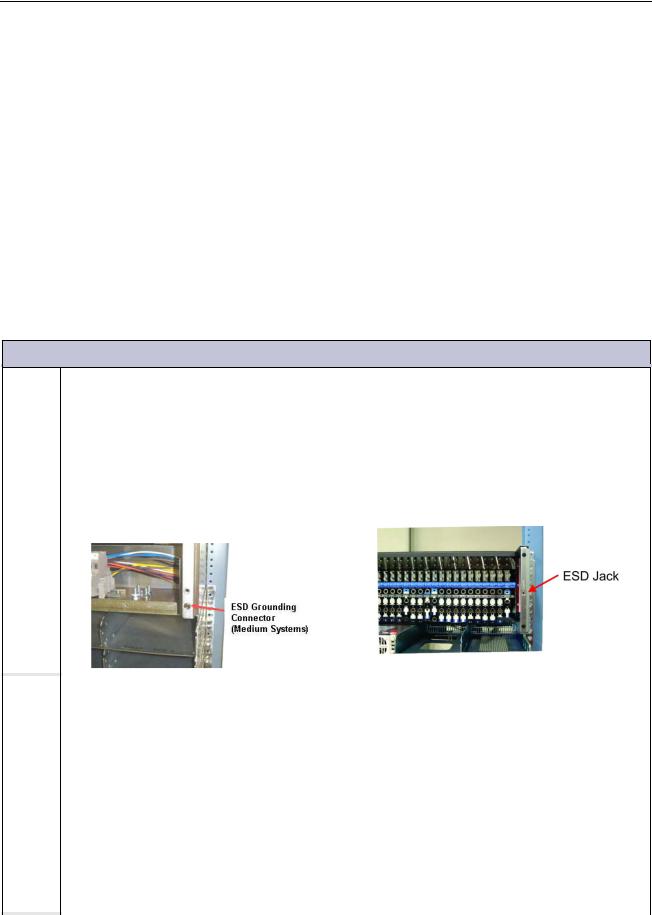
1 |
|
Connect for ESD Prevention |
||
|
|
|
|
|
|
NE843C/NE843E/NE843P |
|
|
NE843A/CP843A/EP843D |
|
Attach an ESD wrist strap or equivalent to |
Attach an ESD wrist strap or equivalent to the |
||
|
the ESD grounding connector on right hand |
ESD grounding connector inside the distribution |
||
|
side of the inside of the |
frame in |
the |
panel in front of the battery landings or another |
|
medium system. Visible |
after door |
is |
convenient location. |
|
opened. |
|
|
|
|
|
|
|
|
|
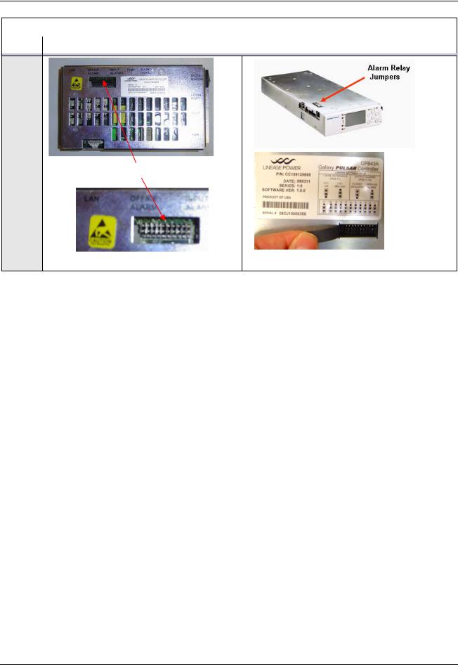
2 |
Configuring Individual Alarm Output Contact Type– “Close” on or “Open” on alarm |
|
|
|
|
The factory default configuration for all alarm outputs is “Open” on alarm. If this acceptable go |
|
|
|
|
to Step 4 otherwise continue. |
|
|
|
|
|
|
|
|
|
Locate configuration jumpers for alarm |
Locate configuration jumpers for alarm relays on |
|
|
|
relays on door-mounted controller. Each of |
slot-mounted controller. Lift the sliding cover on |
|
|
|
the 10 output alarm jumpers is visible. |
the top to access each of the 10 output alarm |
|
|
|
|
jumpers. |
|
|
|
|
|
|
|
|
|
|
|
Issue 7 December 2011 |
18 |
Pulsar Plus Controller Family
|
Install and Configure Slot/Door-Mount Controllers |
|
|
Step |
Action |
|
|
Alarm Relay Jumpers
Issue 7 December 2011 |
19 |
Pulsar Plus Controller Family
|
Install and Configure Slot/Door-Mount Controllers |
|||||||||||||||||||||||||||||||||||||||
|
|
|
|
|
|
|
|
|
|
|
|
|
|
|
|
|
|
|
|
|
|
|
|
|
|
|
|
|
|
|
|
|
|
|
|
|
|
|
|
|
Step |
|
|
|
|
|
|
|
|
|
|
|
|
|
|
|
|
|
|
|
|
Action |
|||||||||||||||||||
|
|
|
|
|
|
|
|
|
|
|
|
|
|
|
|
|
|
|
|
|
|
|
|
|
|
|
|
|
|
|
|
|
|
|
|
|
|
|
|
|
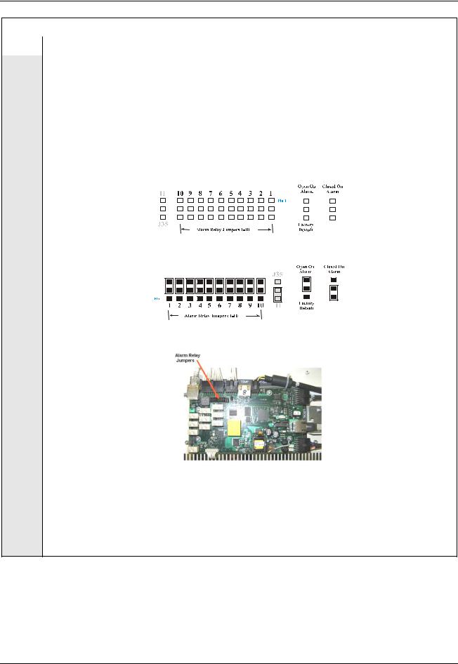
3 |
Configure alarm relays to “Open” or “Close” on alarm as required: |
|||||||||||||||||||||||||||||||||||||||
|
Jumpers 1-10 select the contact type provided at alarm connector J4 for each of the ten alarms. |
|||||||||||||||||||||||||||||||||||||||
|
Carefully move and verify each of respective configuration jumpers to achieve the desired |
|||||||||||||||||||||||||||||||||||||||
|
contact type: “Open On Alarm” or “Closed On Alarm” position. Use of an insulated tool is |
|||||||||||||||||||||||||||||||||||||||
|
suggested. Return the sliding cover on the slot-controller when configuration is complete. Note: |
|||||||||||||||||||||||||||||||||||||||
|
the same control board is utilized in all controller applications. However, the appearance of the |
|||||||||||||||||||||||||||||||||||||||
|
jumpers may seem different because of its orientation in the different packages. Use the |
|||||||||||||||||||||||||||||||||||||||
|
following along with labeling on the controller to assist in setting the jumpers. |
|||||||||||||||||||||||||||||||||||||||
|
|
|
|
|
|
|
|
|
|
|
|
|
|
|
|
|
|
|
|
|
|
|
|
|
|
|
|
|
|
|
|
|
|
|
|
|
|
|
|
|
|
|
|
|
|
|
|
|
|
|
|
|
|
|
|
|
|
|
|
|
|
|
|
|
|
|
|
|
|
|
|
|
|
|
|
|
|
|
|
|
|
|
|
|
|
|
|
|
|
|
|
|
|
|
|
|
|
|
|
|
|
|
|
|
|
|
|
|
|
|
|
|
|
|
|
|
|
|
|
|
|
|
|
|
|
|
|
|
|
|
|
|
|
|
|
|
|
|
|
|
|
|
|
|
|
|
|
|
|
|
|
|
|
|
|
|
|
|
|
|
|
|
|
|
|
|
|
|
|
|
|
|
|
|
|
|
|
|
|
|
|
|
|
|
|
|
|
|
|
|
|
|
|
|
|
|
|
|
|
|
|
|
|
|
|
|
|
|
|
|
|
|
|
|
|
|
|
|
|
|
|
|
|
|
|
|
|
|
|
|
|
|
|
|
|
|
|
|
|
|
|
|
|
|
|
|
|
|
|
|
|
|
|
|
|
|
|
|
|
|
|
|
|
|
|
|
|
|
|
|
|
|
|
|
|
|
|
|
|
|
|
|
|
|
|
|
Slot Controllers - NE843A/CP843A/ED843D
Door Mount Controllers - NE843C/NE843E/NE843P
Microprocessor Board - Integrated into all controllers
Each jumper corresponds to one alarm relay and each relay output can be configured independently. The following table contains the alarms along with the factory default alarm assignments to user relays R1-R7. Utilize the web or EasyView interface to reassign any of the alarm outputs to specific alarm events or to change the severity of the alarms.
Issue 7 December 2011 |
20 |
Pulsar Plus Controller Family
Install and Configure Slot/Door-Mount Controllers
Step |
|
|
|
Action |
|
|
|
|
|
|
|
|
|
|
|
|
|
|
|
|
|
|
Jumper |
Signal |
Table 2 Controller Standard Defaults Door Mounted |
|
|
|
|
Number |
Name |
|
||
|
|
|
|
|
||
|
|
|
|
Pulsar Plus Display |
Phoenix Display |
|
|
|
1 |
PCR |
Power Critical Alarm severity indicator |
|
|
|
|
|
|
|
|
|
|
|
2 |
PMJ |
Power Major Alarm severity indicator |
|
|
|
|
|
|
|
|
|
|
|
3 |
PMN |
Power Minor Alarm severity indicator |
|
|
|
|
|
|
|
|
|
|
|
4 |
R1 |
Battery on Discharge alarm |
AC/Multiple AC Fail |
|
|
|
(BD) |
(ACF, MACF) |
|
||
|
|
|
|
|
||
|
|
|
|
|
|
|
|
|
|
|
Very Low Voltage alarm |
Battery on Discharge, Battery Test |
|
|
|
5 |
R2 |
Active |
|
|
|
|
(VLV) |
|
|||
|
|
|
|
(BD, BTA) |
|
|
|
|
|
|
|
|
|
|
|
|
|
|
|
|
|
|
|
|
Fuse Alarm |
Distribution Fuse/CB Alarm, Open |
|
|
|
6 |
R3 |
String |
|
|
|
|
(FAJ1/2/FAN1/2) |
|
|||
|
|
|
|
(FAJ1/2, FAN1/2, CDFA, AMJ, OSA) |
|
|
|
|
|
|
|
|
|
|
|
|
|
|
|
|
|
|
7 |
R4 |
AC Fail alarm |
High Voltage |
|
|
|
(ACF) |
(HVA, HFV) |
|
||
|
|
|
|
|
||
|
|
|
|
|
|
|
|
|
|
|
Rectifier/Converter Fail |
Rectifier Fail, Incompatible |
|
|
|
8 |
R5 |
alarm |
Rectifier |
|
|
|
|
|
(RFA/ CFA) |
(RFA, RFN, ICR) |
|
|
|
|
|
|
|
|
|
|
|
|
Multiple Fail alarm |
|
|
|
|
9 |
R6 |
Rectifier/Converter/AC |
Multiple Rectifier Fail |
|
|
|
(MACF/MRFA/ |
(MRFA/MFA) |
|
||
|
|
|
|
|
||
|
|
|
|
MCFA/MMAN) |
|
|
|
|
|
|
|
|
|
|
|
|
|
|
Converter Fail/Multiple Converter |
|
|
|
|
|
|
Fail, Converter Redundancy Loss, |
|
|
|
|
|
High Voltage alarm - |
Converter Low Voltage, Converter |
|
|
|
10 |
R7 |
Rectifier and Converter |
High Voltage, Converter ID |
|
|
|
|
|
(HVA/HFV/CHVA/CHFV |
Conflict |
|
|
|
|
|
|
(CFA, MCFA, CFN, CRL, CVLA, |
|
|
|
|
|
|
CHVA, CHFV, CDID) |
|
|
|
|
|
|
|
|
|
|
|
|
|
|
|
If your system using the optional ES771 Mid-String Voltage Modules continue with Step 4. Otherwise go to step 5.
Issue 7 December 2011 |
21 |
Pulsar Plus Controller Family
|
Install and Configure Slot/Door-Mount Controllers |
|
|
Step |
Action |
|
|
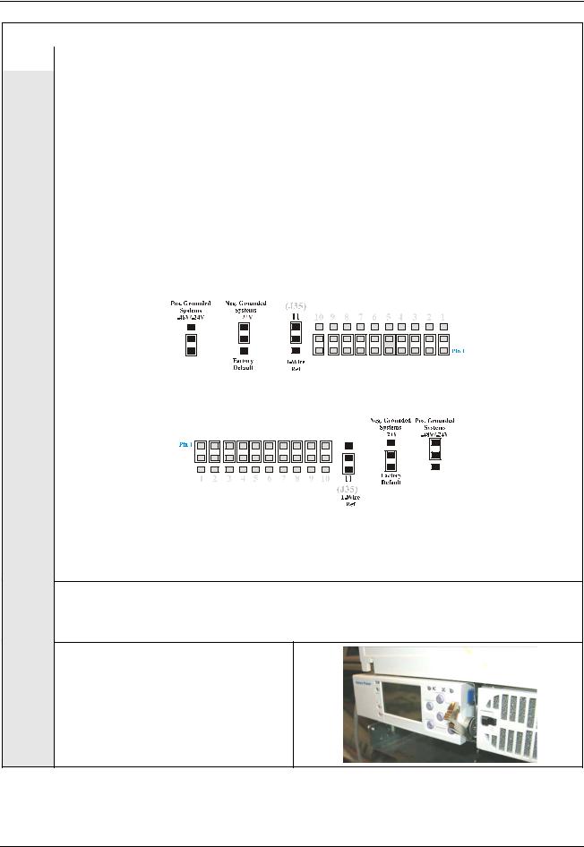
4 |
Configure the 1-Wire serial bus reference: |
The ES771 modules must be referenced to the most negative potential of the DC bus. This reference is achieved by the proper setting of Jumper 11 (board reference J35) that is located next to the alarm relay configuration jumpers. The jumper is set in the factory for Positive Grounded systems (-48V) unless the controller is shipped with an assembled system that has a pre-determined primary output bus. An insulated tool must be used to set the jumpers.
For systems with Positive Grounded batteries (-48V/-24V), move 1-Wire Reference jumper 11 (J35) to the Positive Grounded position. For systems with Negative Grounded batteries (+24V), move jumper 11 (J35) to the Negative Grounded position as shown: Again, the appearance of the jumpers may seem different when the controller is a slot-controller or a door-mount controller because of the orientation of the circuit board.
Slot Controllers - NE843A/CP843A/ED843D
Door Mount Controllers - NE843C/NE843E/NE843P
Make sure the jumper cover is returned in slot-mount controllers.
|
Securing the Slot-Mounted Controller |
|
For NE843C/NE843E based systems go to next section on connecting the controller. The |
|
following is for the NE843A/CP843A/EP843D slot-controllers. |
|
Place the NE843A/CP843A slot-mounted |
5 |
controllers into a left-most power. The |
|
EP843D goes into the right-most power |
|
slot. |
|
Open the latch on right-hand side of the |
|
front panel by pushing down on the edge |
|
of the “blue” latch tab. |
Issue 7 December 2011 |
22 |
Pulsar Plus Controller Family
Install and Configure Slot/Door-Mount Controllers
Step |
|
|
|
|
Action |
|
|
|
|
|
|
6 |
|
|
|
|
|
|
Push the controller firmly into the shelf |
|
|||
|
until seated. Attach or reattach all cable |
|
|||
|
connections |
to |
the |
appropriate |
|
|
connections located on the side of the |
|
|||
|
controller. |
|
|
|
|
|
|
|
|||
7 |
Close the latch. The controller is now installed. |
||||
|
|
|
|
|
|
|
|
|
|
|
|
Install and Configure Pulsar Plus NE843G Controller
Although the NE843G frame-mount controller is very similar to the NE843A, CP843A, and EP843D Slot controllers and the NE843C and NE843E door/panel-mount controllers a separate section is provided since its packaging is the most different. However, the basic steps are very similar.
The controller is available factory installed into a door/panel of a power system, supplied as a removable slot controller, or provided as 1U frame mount controller. All these controllers utilize the same main microprocessor board. All functions, inputs, and outputs described are applicable to all controller configurations. The differences in the controllers are due the nuances of the physical packaging. Before power is applied, some basic configuration may be required that is applicable to all configurations.
|
Install and Configure Pulsar Plus NE843G Controller |
|
|
Step |
Action |
|
|
1 |
Connect for ESD Prevention |
|
The NE843G is typically mounted into a customer premise frame. If the output alarm contacts |
|
need to be changed from “Open On Alarm” to “Close On Alarm” or the 1-Wire bus needs to be |
|
referenced for a +24V power system then the cover will need to be removed to change jumper |
|
settings. Jumper configuration can be performed with the unit installed in the frame or not. |
|
Depending on the available space in a frame it may be easier to change the jumper settings |
|
when the unit is not mounted into the frame. Use appropriate ESD techniques when removing |
|
the cover and changing the jumpers. |
|
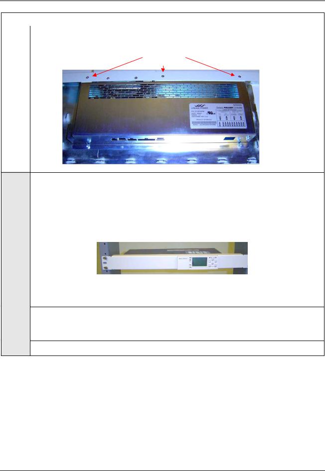
Remove the three M3 Phillips head screws and #4-40 hex nuts with lock washers shown in the |
|
following figure. Do not remove other screws. Gently pull up on the rear side of the cover as you |
|
slide the cover towards the back to remove the cover. (Note: reverse these steps to put the |
|
cover back on the unit). |
|
|
Issue 7 December 2011 |
23 |
Pulsar Plus Controller Family
|
Install and Configure Pulsar Plus NE843G Controller |
|
|
Step |
Action |
|
|
|
M3 Screws |
|
|
2 |
Frame Mounting |
|
The NE843G is designed to flush-fit into standard 19” frame rails. Extension brackets are |
|
available to mount the unit into standard 23” frame rails. Use the #12 paint piercing ground |
|
washers (12NWGRO/T2) along with the six 12-24 self-tapping screws (CC408577571) to mount |
|
the NE843G to the frame. Use at least two screws per side. The controller is typically mounted |
|
over the top of a J85480S1 L1 or L4 rectifier shelf but can also be mounted below. |
Note: Return to this section if changing the jumper settings with the unit not installed in the frame.
3Configure Individual Alarm Output Contact Type– “Close” on or “Open” on alarm
The factory default configuration for all alarm outputs is “Open” on alarm. If this acceptable go to Step 8. Otherwise continue.
4If the controller is slot mounted remove it to gain access to the jumpers. Otherwise continue.
Issue 7 December 2011 |
24 |
Pulsar Plus Controller Family
|
Install and Configure Pulsar Plus NE843G Controller |
|
|
Step |
Action |
|
|
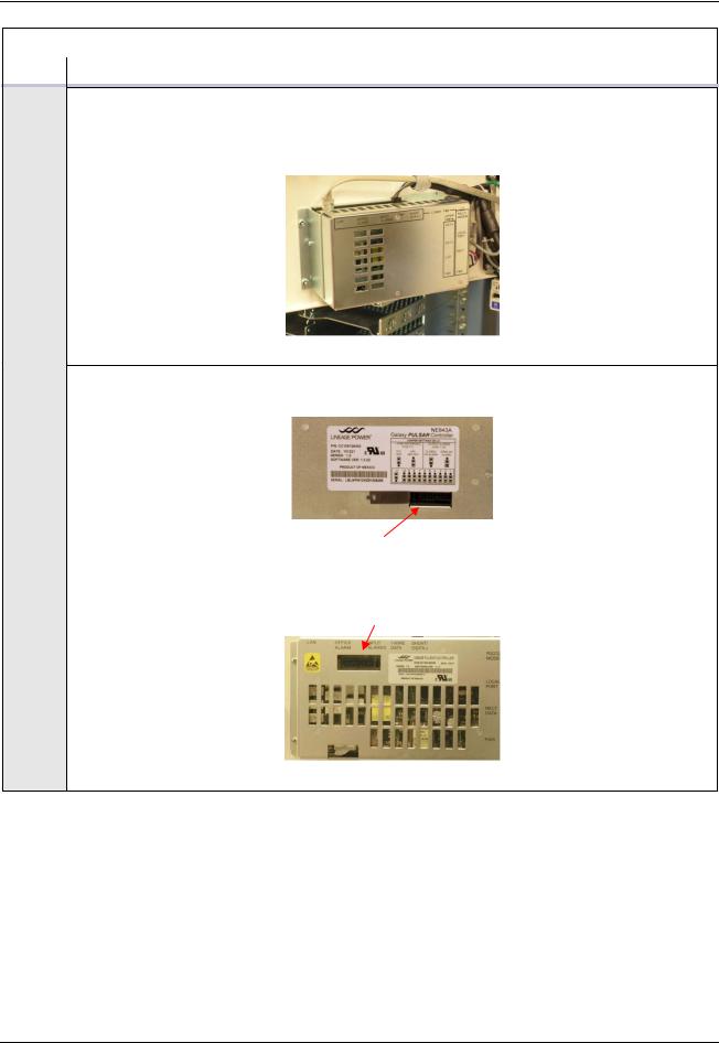
5If an NE-872 Contactor Control Module is mounted on back of Door Mounted Controller remove it to gain access to the jumpers. After removing the mounting screws carefully position the NE872 so that it is not in contact with electrically live components and is supported by the cables connected to it. Otherwise continue.
NE-872 Contactor Control Module
6 Locate configuration jumpers for alarm relays as shown below.
Alarm Jumpers - Slot Controllers - Top of Controller
Alarm Jumpers - Door Mounted Controllers
Issue 7 December 2011 |
25 |
Pulsar Plus Controller Family
|
Install and Configure Pulsar Plus NE843G Controller |
|||||||||||||||||||||||||||||||||||||||||||||||
|
|
|
|
|
|
|
|
|
|
|
|
|
|
|
|
|
|
|
|
|
|
|
|
|
|
|
|
|
|
|
|
|
|
|
|
|
|
|
|
|
|
|
|
|
|
|
|
|
Step |
|
|
|
|
|
|
|
|
|
|
|
|
|
|
|
|
|
|
|
|
|
|
|
|
|
|
|
Action |
||||||||||||||||||||
|
|
|
|
|
|
|
|
|
|
|
|
|
|
|
|
|
|
|
|
|
|
|
|
|
|
|
|
|
|
|
|
|
|
|
|
|
|
|
|
|
|
|
|
|
|
|
|
|
7 |
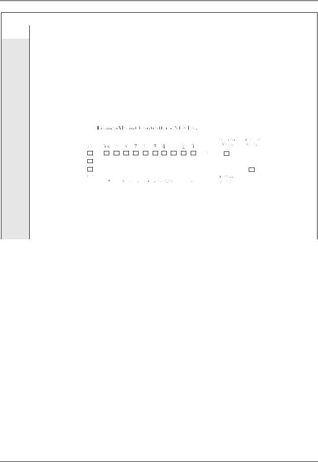
Configure alarm relays to “Open” or “Close” on alarm as required: |
|||||||||||||||||||||||||||||||||||||||||||||||
|
Jumpers 1-10 select the contact type to provide at alarm connector J4 of each respective Form- |
|||||||||||||||||||||||||||||||||||||||||||||||
|
C output for each alarm. Carefully move each of respective configuration jumpers to the desired |
|||||||||||||||||||||||||||||||||||||||||||||||
|
contact type: “Open On Alarm” or “Closed On Alarm” position as required per site instructions. |
|||||||||||||||||||||||||||||||||||||||||||||||
|
Use of an insulated tool is suggested. Return the cover on the controller if finished configuring |
|||||||||||||||||||||||||||||||||||||||||||||||
|
alarm relays and 1-Wire reference adjustment is not required. Note: the same control board is |
|||||||||||||||||||||||||||||||||||||||||||||||
|
utilized in all controller applications. However, the appearance of the jumpers may seem |
|||||||||||||||||||||||||||||||||||||||||||||||
|
different because of its orientation in the different packages. Use the following along with |
|||||||||||||||||||||||||||||||||||||||||||||||
|
labeling on the controller to assist in setting the jumpers. |
|||||||||||||||||||||||||||||||||||||||||||||||
|
|
|
|
|
|
|
|
|
|
|
|
|
|
|
|
|
|
|
|
|
|
|
|
|
|
|
|
|
|
|
|
|
|
|
|
|
|
|
|
|
|
|
|
|
|
|
|
|
|
|
|
|
|
|
|
|
|
|
|
|
|
|
|
|
|
|
|
|
|
|
|
|
|
|
|
|
|
|
|
|
|
|
|
|
|
|
|
|
|
|
|
|
|
|
|
|
|
|
|
|
|
|
|
|
|
|
|
|
|
|
|
|
|
|
|
|
|
|
|
|
|
|
|
|
|
|
|
|
|
|
|
|
|
|
|
|
|
|
|
|
|
|
|
|
|
|
|
|
|
|
|
|
|
|
|
|
|
|
|
|
|
|
|
|
|
|
|
|
|
|
|
|
|
|
|
|
|
|
|
|
|
|
|
|
|
|
|
|
|
|
|
|
|
|
|
|
|
|
|
|
|
|
|
|
|
|
|
|
|
|
|
|
|
|
|
|
|
|
|
|
|
|
|
|
|
|
|
|
|
|
|
|
|
|
|
|
|
|
|
|
|
|
|
|
|
|
|
|
|
|
|
|
|
|
|
|
|
|
|
|
|
|
|
|
|
|
|
|
|
|
|
|
|
|
|
|
|
|
|
|
|
|
|
|
|
|
|
|
|
|
|
|
|
|
|
|
|
|
|
|
|
|
|
|
|
|
|
|
|
|
|
|
|
|
|
|
|
|
|
|
|
|
|
|
|
|
|
|
|
|
|
|
|
|
|
|
|
|
|
|
|
|
|
|
|
|
|
|
|
|
|
|
|
|
|
|
|
|
|
|
|
|
|
|
|
|
|
|
|
|
|
|
|
|
|
|
|
|
|
|
|
|
|
|
|
|
|
|
|
|
|
|
|
|
|
|
|
|
|
|
|
|
|
|
|
|
|
|
|
|
|
|
|
|
|
|
|
|
|
|
|
|
|
|
|
|
|
|
|
|
|
|
|
|
|
|
|
|
|
|
|
|
|
|
|
|
|
|
|
|
|
|
|
|
|
|
|
|
|
|
|
|
|
|
|
|
|
|
|
|
|
|
|
|
|
|
|
|
|
|
|
|
|
|
|
|
|
|
|
|
|
|
|
|
|
|
|
|
|
|
|
|
|
|
|
|
|
|
|
|
|
|
|
|
|
|
|
|
|
|
|
|
|
|
|
|
|
|
|
|
|
|
|
|
|
|
|
|
|
|
|
|
|
|
|
|
|
|
|
|
|
|
|
|
|
|
|
|
|
|
|
|
|
|
|
|
|
|
|
|
|
|
|
|
|
|
|
|
|
|
|
|
|
|
|
|
|
Each jumper corresponds to one output alarm relay contact that can be independently configured. The alarm table shown in Step 3 previously is also applicable for this controller but repeated below for convenience. Utilize the web or EasyView interface to change any of the alarm user relay alarm assignments.
Issue 7 December 2011 |
26 |

Pulsar Plus Controller Family
Install and Configure Pulsar Plus NE843G Controller
Step |
|
|
|
Action |
|
|
|
|
|
|
|
|
|
|
|
|
|
|
|
Jumper |
Signal |
Table 3 Table 2 Controller Standard Defaults NE843G |
|
|
|
|
|||
|
|
Number |
Name |
|
|
|
|
|
|
||
|
|
|
|
|
|
|
|
1 |
PCR |
Power Critical Alarm severity indicator |
|
|
|
|
|
|
|
|
|
2 |
PMJ |
Power Major Alarm severity indicator |
|
|
|
|
|
|
|
|
|
3 |
PMN |
Power Minor Alarm severity indicator |
|
|
|
|
|
|
|
|
|
4 |
R1 |
Battery on Discharge alarm |
|
|
|
(BD) |
|
||
|
|
|
|
|
|
|
|
|
|
|
|
|
|
5 |
R2 |
AC and Multiple AC Fail alarm (ACF/MACF) |
|
|
|
|
|
|
|
|
|
6 |
R3 |
Rectifier/Converter Fail alarm |
|
|
|
(RFA/MRFA/CFA/MCFA) |
|
||
|
|
|
|
|
|
|
|
|
|
|
|
|
|
7 |
R4 |
Very Low Voltage alarm |
|
|
|
(VLV) |
|
||
|
|
|
|
|
|
|
|
|
|
|
|
|
|
8 |
R5 |
Fuse Alarm - 48V |
|
|
|
(External FAJ2/FAN2) |
|
||
|
|
|
|
|
|
|
|
|
|
|
|
|
|
9 |
R6 |
High Voltage alarm |
|
|
|
(HV) |
|
||
|
|
|
|
|
|
|
|
|
|
|
|
|
|
10 |
R7 |
Fuse Alarm - 24V |
|
|
|
(External FAJ1/FAN1) |
|
||
|
|
|
|
|
|
|
|
|
|
|
|
8 |
|
If your system using optional ES771 Mid-String Voltage Modules continue. Otherwise go to |
|||
|
step 10. |
|
|
|
|
|
|
|
|
|
|
|
|
|
|
|
|
Issue 7 December 2011 |
27 |
Pulsar Plus Controller Family
|
Install and Configure Pulsar Plus NE843G Controller |
|
|
Step |
Action |
|
|
9 |
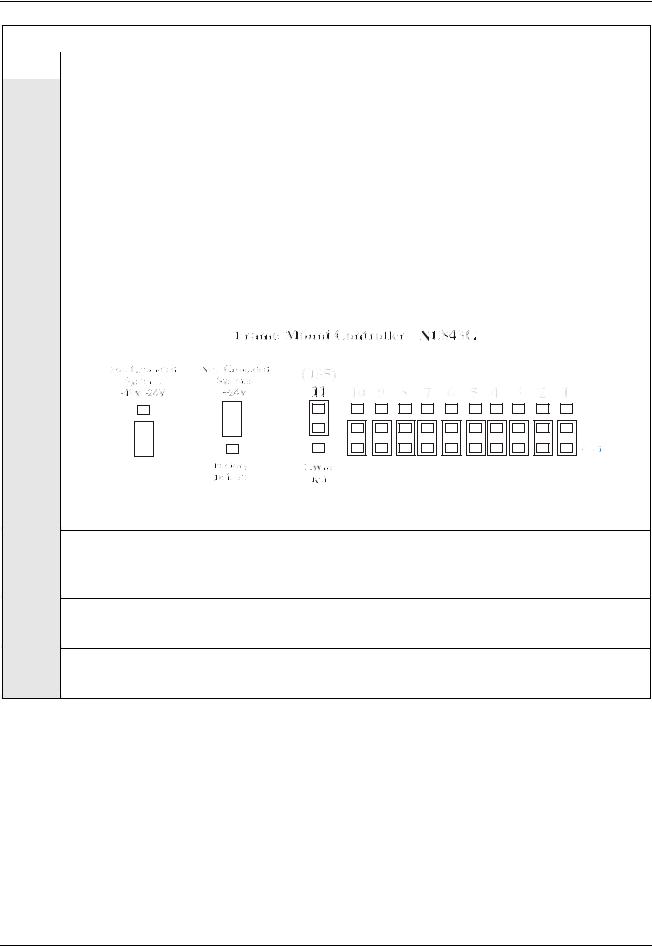
Configure The 1-Wire Serial Bus Reference: |
The ES771 modules must be referenced to the most negative potential of the DC bus. This reference is achieved by the proper setting of Jumper 11 (board reference J35) that is located next to the alarm relay configuration jumpers. The jumper is set in the factory for Positive Grounded systems (-48V) unless the controller is shipped with an assembled system that has a pre-determined primary output bus. An insulated tool must be used to set the jumpers.
For systems with Positive Grounded batteries (-48V/-24V), move 1-Wire Reference jumper 11 (J35) to the Positive Grounded position. For systems with Negative Grounded batteries (+24V), move jumper 11 (J35) to the Negative Grounded position as shown: Again, the appearance of the jumpers may seem different when the controller is a frame-mount controller because of the orientation of the circuit board.
Return the cover to the unit.
10 |
Securing The NE-872 Contactor Control Module |
|
If the NE-872 Contactor Control Module unit was removed from the back of the door mounted |
|
controller replace it and tighten its mounting screws. Otherwise continue to step 7. |
11 |
Securing The Slot Mounted Controller |
|
If the sloe mounted controller was removed replace it. Otherwise continue to step 8. |
12 |
Securing The Frame-Mounted Controller |
If the unit was not mounted into the frame see Step 2. Otherwise this portion is complete.
Issue 7 December 2011 |
28 |

Pulsar Plus Controller Family
Connect To the Controller
Connections to the controller are made through appropriate cable assemblies either directly to the main board or automatically for direct backplane interconnects. The controller is designed with individual connectors for outputs, inputs, communication, and other specific system related items. Primary system interconnects are oriented at the top and right side edges of the NE843C/NE843E/NE843P door-mounted units, on the left side of the unit’s NE843A/CP843A slot-mounted controllers, at the rear of the NE843G, and at the front of the EP843D. The following information is valid for all configurations since the same main microprocessor board is utilized in the different controller packages. Slight differences due to packaging will be noted.
NE843C/NE843E/NE843P
NE843A/CP843A
NE843G
Many systems are shipped with the controller pre-wired in the factory. The following steps provides a brief description of how and what to connect to the controller if these connections are to be made in the field. Use only those that apply to the system configuration.
Issue 7 December 2011 |
29 |

Pulsar Plus Controller Family
|
|
|
|
Connect to the Controller |
|
Step |
|
|
|
Action |
|
1 |
|
|
|
Plant Interface Connector |
|
|
J1 is a 6-pin connector provided for interfacing inputs required for basic plant operation in specific |
||||
|
system configurations. These inputs include a single plant shunt, (2) distribution alarms, and open |
||||
|
battery string alarm. J1 connections are typically made in the factory with a specific wire harness |
||||
|
for a given system. Following is a brief description of the inputs. |
||||
|
|
|
|
|
|
|
|
Pin |
Signal |
Description |
|
|
|
|
Name |
|
|
|
|
1 |
Shunt+ |
Shunt + is the more positive lead from a system battery or load shunt. |
|
|
|
|
|
For battery shunts, this is the most positive lead of shunt during a |
|
|
|
|
|
discharge. The shunt may reside in the grounded or non-grounded side |
|
|
|
|
|
of the DC bus (±24V/-48V) as long as the Shunt Reference lead is |
|
|
|
|
|
connected correctly. This lead must comply with Class II wiring |
|
|
|
|
|
standards. |
|
|
|
2 |
Shunt |
This signal is used to reference the shunt analog measurement circuits to |
|
|
|
|
Reference |
either the battery or ground side of a system. The reference must be |
|
|
|
|
|
attached to the same potential or side that the monitored shunt resides. |
|
|
|
|
|
This lead must comply with Class II wiring standards. |
|
|
|
3 |
Shunt- |
Shunt - is the more negative lead from a system battery or load shunt. |
|
|
|
|
|
For battery shunts, this is the most negative lead of shunt during a |
|
|
|
|
|
discharge. The shunt may reside in the grounded or non-grounded side |
|
|
|
|
|
of the DC bus (±24V/-48V). This lead must comply with class II wiring. |
|
|
|
4 |
Fuse Alarm |
FAJ1 is the input monitor for distribution that accepts a contact to |
|
|
|
|
Major - 24V |
Battery for ±24V DC systems as an alarm. Factory default for FAJ1 is to |
|
|
|
|
|
alarm on application of DC bus voltage. Can be reconfigured as needed |
|
|
|
|
|
through the web interface. |
|
|
|
5 |
Open String |
OS1 is the input monitor that accepts a contact to Battery for ±24V/-48V |
|
|
|
|
|
DC systems to identify an open battery string. Factory default for OS1 is |
|
|
|
|
|
to alarm on application of DC bus voltage. Can be reconfigured as |
|
|
|
|
|
needed through the web interface. |
|
|
|
6 |
Fuse Alarm |
FAJ2 is the input monitor for that accepts a contact to Battery for -48V |
|
|
|
|
Major -48V |
DC systems as an alarm. Factory default for FAJ2 is to alarm on |
|
|
|
|
|
application of DC bus voltage. Can be reconfigured as needed through |
|
|
|
|
|
the web interface. |
|
|
|
|
|
|
|
Issue 7 December 2011 |
30 |
Loading...