


g
DEH41025 Installation Instructions
Record Plus ™
Molded Case Circuit Breaker
Accessories
Rotary Handle Operator, Type
FENRH
Congratulations and thank you for choosing the Record Plus™ family of current-limiting circuit breakers. The UL-listed Type FENRH rotary handle operator kit is suitable for use with the FE250 circuit breaker series.
Record Plus™ circuit breakers are designed with a full line of integrated accessories. All units use the latest in integrated modular circuit breaker technology for flexibility in application and maximizing the product’s utilization and capabilities.
All Record Plus™ circuit breakers are listed by Underwriters Laboratories to the UL489 standard.
Record Plus™ circuit breakers and their accessories are designed and manufactured to exceed our global customers’ high standards for reliability and quality.
 WARNING: DANGER of electrical shock or injury. Ensure that ALL electrical power supplies are OFF before installing or removing any devices. The breaker, trip unit, or accessories MUST ONLY be installed and serviced by QUALIFIED personnel. See NEMA publication AB4.
Figure 1a. FENRN
(Shallow Door Mount).
Figure 1b. FENRT
(Extended Shaft Door Mount).
Figure 1. FENRH Rotary Handle Kits mounted on Record Plus™ FE250 circuit breaker.
AVERTISSEMENT: Danger contre les risques d'électrocutions. S'assurer avant TOUTES manipulations du disjoncteur que les différentes sources d'alimentation sont en position OFF. Les disjoncteurs, unités de protection, ou accessoires doivent être installés par des personnes qualifiées et habilitées. Lira NEMA publication AB4.
CAUTION: This product is NOT suitable for use in equipment not specifically design to accept it. Contact the equipment manufacturer for possible equipment modifications.
ATTENTION: Cet appareil nedoit pas etre employe dans un equipement non specialement adapte a cet effet. Contactez le constructeur concernant les possibles modifications a apporter a l'equipement.
DEH41025
Product Description
These instructions describe the installation procedures for the rotary handle FENRH operating mechanism accessory on Record Plus™ circuit breakers, as illustrated in Figure 1.
The complete kits are available in the following catalog number variants:
•FENRN provides the necessary parts for shallow door mount of the handle on the breaker
mechanism through the enclosure door, with a box depth of 5 29/32“ (150 mm), as shown in
Figure 1a. Maintain the dimension “H” [5 1/32” (127.8 MM)] as shown in Figure 12.
•FENRT is for mounting the handle and operator in enclosures with variable depth, as
shown in Figure 1b. Maintain the dimension “H” [Min 6 13/16“ inches (173 mm) and Max 15 inches (381.0 mm)] as shown in Figure 13.
In addition, the individual kit parts are available as follows:
•FENRM1 consists of the operating mechanism for shallow door mounts of the handle to the breaker.
•FENRM3 consists of the operating mechanism for extended shaft door mount of the handle.
•FENRH is the handle assembly only.
Step 1 – Unpack and Inspect
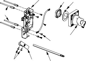
Unpack the rotary handle operating mechanism kit and inspect the parts for any shipping damage. Verify that all parts are supplied, as listed in Table 1. The parts are illustrated in Figure 2.
Note that the numbers in brackets in the following figures and installation instructions refer to the item numbers in Table 1.
Item |
Description |
Qty. |
1 |
Screw, #10-32 X 3 5/32" |
4 |
2 |
Base-crank assembly |
1 |
3 |
Grounding wire |
1 |
4 |
Screw, #10-32 x 1/2" |
4 |
5 |
Nut, plastic |
1 |
6 |
Rotary handle assembly |
1 |
7 |
Screw, #8-32 x 5/16" |
4 |
8 |
Coupler Assembly |
1 |
9 |
Extension shaft |
1 |
|
assembly |
|
10 |
Gasket |
1 |
Table 1. List of parts included in the handle operator kits.
[2] |
[5] |
[10] |
[1]
 [3]
[3]
[6]
 [4]
[4]
[7] |
[8] |
[9] |
|
|
Figure 2. Parts supplied in the FENRH rotary handle kits.
Step 2 – Install the Breaker and
Handle Operating Mechanism
1.Move the breaker handle to the OFF position.
2.Mount the breaker to the enclosure with the # 1032 x 3 5/32" screws [1], as illustrated in Figure 3. Tighten the screws to 27 - 32 in-lb. Complete the installation of the circuit breaker according to installation instructions DEH40360.
3.Place the base-crank assembly [2] on the breaker, as illustrated in Figure 4. Insert four #10-32 x 1/2" screws [4] through the mounting holes in the base and into the heads of the breaker mounting screws [1], with the grounding wire [3] attached to one of the screws. Tighten the screws to 27 - 32 in-lb. Secure the other end of the grounding wire to a suitable ground location.
4.For kit FENRT variable-depth mounting only:
a.Measure the distance from the breakermounting surface to the rotary handlemounting surface, H, as shown in Figures 8 & 13.
b.Cut the extension shaft [9] to the required length “L” as illustrated in Figure 5.
c.Insert the shaft [9] upto 14 mm (35/64“ inch)
into the coupler [8] and secure it with #8-32 X 1/32“ screws [7], as illustrated in Figure 6. Tighten the screws to 16 - 20 in-lb.
d.Place the shaft [9] assembled with coupler
[8]on to the crank of the base-crank assembly
[2]and secure with #8-32 x 5/16“ screws [7], as illustrated in Figure 7. Tighten the screws to 16 - 20 in-lb.
DEH41025
 Loading...