


GE
AF-600 FPTM
Fan & Pump Drive
(230V to 60HP, 460/575V to 125HP
Operating Instructions
Safety |
AF-600 FP Operating Instructions |
|
|
Safety

 WARNING
HIGH VOLTAGE!
Frequency converters contain high voltage when connected to AC mains input power. Installation, start up, and maintenance should be performed by qualified personnel only. Failure to perform installation, start up, and maintenance by qualified personnel could result in death or serious injury.
High Voltage
Frequency converts are connected to hazardous mains voltages. Extreme care should be taken to protect against shock. Only trained personnel familiar with electronic equipment should install, start, or maintain this equipment.

 WARNING
UNINTENDED START!
When the drive is connected to AC mains, the motor may start at any time. The drive, motor, and any driven equipment must be in operational readiness. Failure to be in operational readiness when the drive is connected to AC mains could result in death, serious injury, equipment, or property damage.
Unintended Start
When the drive is connected to the AC mains, the motor may be started by means of an external switch, a serial bus command, an input reference signal, or a cleared fault condition. Use appropriate cautions to guard against an unintended start.

 WARNING
DISCHARGE TIME!
Frequency converters contain DC link capacitors that can remain charged even when AC mains is disconnected. To avoid electrical hazards, remove AC mains from the drive before doing any service or repair and wait the amount of time specified in Table 1.1. Failure to wait the specified time after power has been removed prior to doing service or repair on the unit could result in death or serious injury.
Voltage (V) |
Minimum Waiting Time (Minutes) |
|
|
|
|
|
4 |
15 |
|
|
|
200 - 240 |
0.75 - 3.7 kW |
5.5 - 45 kW |
|
1 - 5 hp |
7 1/2 - 60 hp |
|
|
|
380 - 480 |
0.75 - 7.5 kW |
11 - 90 kW |
|
1 - 10 hp |
15 - 125 hp |
|
|
|
525 - 600 |
0.75 - 7.5 kW |
11 - 90 kW |
|
1 - 10 hp |
15 - 125 hp |
High voltage may be present even when the warning LEDs are off!
Discharge Time
Symbols
The following symbols are used in this manual.

 WARNING
Indicates a potentially hazardous situation which, if not avoided, could result in death or serious injury.

 CAUTION
Indicates a potentially hazardous situation which, if not avoided, may result in minor or moderate injury. It may also be used to alert against unsafe practices.
CAUTION
Indicates a situation that may result in equipment or property-damage-only accidents.
NOTE
Indicates highlighted information that should be regarded with attention to avoid mistakes or operate equipment at less than optimal performance.
Approvals

Safety |
AF-600 FP Operating Instructions |
|
|

Contents |
AF-600 FP Operating Instructions |
|
|
|
|
Contents |
|
|
|
1 Introduction |
4 |
|
1.1 Purpose of the Manual |
6 |
|
1.2 Additional Resources |
6 |
|
1.3 Product Overview |
6 |
|
1.4 Internal Drive Controller Functions |
6 |
|
1.5 Unit Sizes and Power Ratings |
7 |
|
2 Installation |
8 |
|
2.1 Installation Site Check List |
8 |
|
2.2 Drive and Motor Pre-installation Check List |
8 |
|
2.3 Mechanical Installation |
8 |
|
2.3.1 Cooling |
8 |
|
2.3.2 Lifting |
9 |
|
2.3.3 Mounting |
9 |
|
2.3.4 Tightening Torques |
9 |
|
2.4 Electrical Installation |
10 |
|
2.4.1 Requirements |
11 |
|
2.4.2 Earth (Grounding) Requirements |
12 |
|
2.4.2.1 Leakage Current (>3,5mA) |
12 |
|
2.4.2.2 Grounding Using Shielded Cable |
13 |
|
2.4.2.3 Grounding Using Conduit |
13 |
|
2.4.3 Motor Connection |
13 |
|
2.4.4 AC Mains Connection |
14 |
|
2.4.5 Control Wiring |
15 |
|
2.4.5.1 Access |
15 |
|
2.4.5.2 Control Terminal Types |
15 |
|
2.4.5.3 Wiring to Control Terminals |
16 |
|
2.4.5.4 Using Screened Control Cables |
17 |
|
2.4.5.5 Control Terminal Functions |
17 |
|
2.4.5.6 Terminal 53 and 54 Switches |
17 |
|
2.4.6 Serial Communication |
18 |
|
3 Start Up and Functional Testing |
19 |
|
3.1 Pre-start |
19 |
|
3.1.1 Safety Inspection |
19 |
|
3.1.2 Start Up Check List |
20 |
|
3.2 Applying Power to the Drive |
21 |
|
3.3 Basic Operational Programming |
21 |
|
3.4 Auto Tune |
21 |
|
3.5 Check Motor Rotation |
22 |
1

Contents |
AF-600 FP Operating Instructions |
|
|
3.6 Local-control Test |
22 |
3.7 System Start Up |
23 |
4 User Interface |
24 |
4.1 Keypad |
24 |
4.1.1 Keypad Layout |
24 |
4.1.2 Setting Keypad Display Values |
25 |
4.1.3 Display Menu Keys |
25 |
4.1.4 Navigation Keys |
26 |
4.1.5 Operation Keys |
26 |
4.2 Back Up and Copying Parameter Settings |
26 |
4.2.1 Uploading Data to the keypad |
27 |
4.2.2 Downloading Data from the keypad |
27 |
4.3 Restoring Default Settings |
27 |
4.3.1 Recommended Initialisation |
27 |
4.3.2 Manual Initialisation |
27 |
5 About Drive Programming |
28 |
5.1 Introduction |
28 |
5.2 Programming Example |
28 |
5.3 Control Terminal Programming Examples |
30 |
5.4 International/North American Default Parameter Settings |
31 |
5.5 Parameter Menu Structure |
32 |
5.5.1 Quick Menu Structure |
32 |
5.5.2 Main Menu Structure |
33 |
5.6 Remote Programming with DCT-10 |
40 |
6 Application Set-Up Examples |
41 |
6.1 Introduction |
41 |
6.2 Application Examples |
41 |
7 Status Messages |
46 |
7.1 Status Display |
46 |
7.2 Status Message Definitions Table |
46 |
8 Warnings and Alarms |
49 |
8.1 System Monitoring |
49 |
8.2 Warning and Alarm Types |
49 |
8.3 Warning and Alarm Displays |
49 |
8.4 Warning and Alarm Definitions |
50 |
8.4.1 Fault Messages |
51 |
9 Basic Troubleshooting |
57 |
2

Contents |
AF-600 FP Operating Instructions |
|
|
9.1 Start Up and Operation |
57 |
10 Specifications |
59 |
10.1 Power-dependent Specifications |
59 |
10.2 General Technical Data |
66 |
10.3 Fuse Tables |
71 |
10.3.1 Recommendations |
71 |
10.3.2 CE Compliance |
72 |
10.3.3 NEC and UL Compliance |
77 |
10.3.4 Substitute Fuses for 240 V |
83 |
10.4 Connection Tightening Torques |
83 |
Index |
84 |
3
Introduction |
AF-600 FP Operating Instructions |
|
|
1 Introduction
1 1
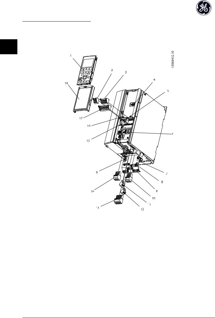
Illustration 1.1 Exploded View Unit Size 1X
1 |
Keypad |
10 |
Motor output terminals 96 (U), 97 (V), 98 (W) |
|
2 |
RS-485 serial bus connector (+68, -69) |
11 |
Relay 1 |
(01, 02, 03) |
|
|
|
|
|
3 |
Analog I/O connector |
12 |
Relay 2 |
(04, 05, 06) |
|
|
|
|
|
4 |
Keypad input plug |
13 |
Brake (-81, +82) and load sharing (-88, +89) terminals |
|
|
|
|
|
|
5 |
Analog switches (A53), (A54) |
14 |
Mains input terminals 91 (L1), 92 (L2), 93 (L3) |
|
|
|
|
|
|
6 |
Cable strain relief / PE ground |
15 |
USB connector |
|
|
|
|
|
|
7 |
Decoupling plate |
16 |
Serial bus terminal switch |
|
|
|
|
|
|
8 |
Grounding clamp (PE) |
17 |
Digital I/O and 24 V power supply |
|
|
|
|
|
|
9 |
Shielded cable grounding clamp and strain relief |
18 |
Control cable cover plate |
|
|
|
|
|
|
4
Introduction |
AF-600 FP Operating Instructions |
|
|
1 1
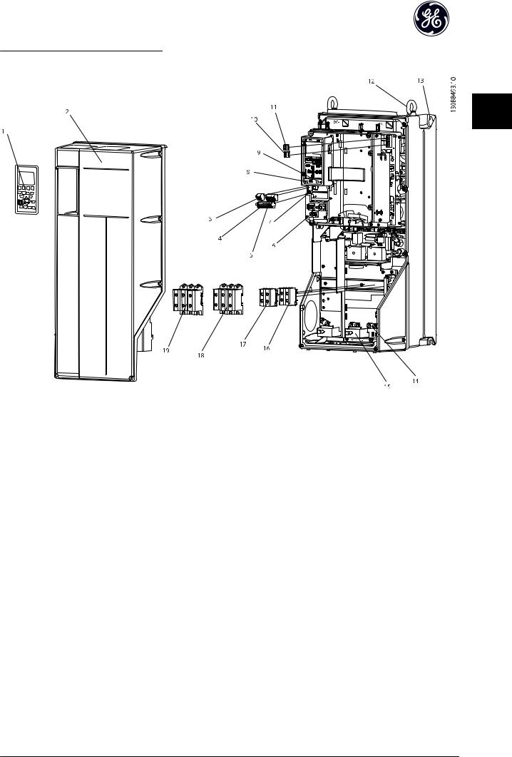
Illustration 1.2 Exploded View Unit Sizes 21, 22, 31, and 32
1 |
Keypad |
11 |
Relay 2 (04, 05, 06) |
|
|
|
|
2 |
Cover |
12 |
Lifting ring |
|
|
|
|
3 |
RS-485 serial bus connector |
13 |
Mounting slot |
|
|
|
|
4 |
Digital I/O and 24 V power supply |
14 |
Grounding clamp (PE) |
|
|
|
|
5 |
Analog I/O connector |
15 |
Cable strain relief / PE ground |
|
|
|
|
6 |
Cable strain relief / PE ground |
16 |
Brake terminal (-81, +82) |
|
|
|
|
7 |
USB connector |
17 |
Load sharing terminal (DC bus) (-88, +89) |
|
|
|
|
8 |
Serial bus terminal switch |
18 |
Motor output terminals 96 (U), 97 (V), 98 (W) |
9 |
Analog switches (A53), (A54) |
19 |
Mains input terminals 91 (L1), 92 (L2), 93 (L3) |
10 |
Relay 1 (01, 02, 03) |
|
|
5

Introduction |
AF-600 FP Operating Instructions |
||||||||||||||||||||||||||||||||||||||||||||||||||||||||||||||||||||
|
|
|
|
|
|
|
|
|
|
|
|
|
|
|
|
|
|
|
|
|
|
|
|
|
|
|
|
|
|
|
|
|
|
|
|
|
|
|
|
|
|
|
|
|
|
|
|
|
|
|
|
|
|
|
|
|
|
|
|
|
|
|
|
|
|
|
|
|
|
|
|
|
|
|
|
|
|
|
|
|
|
|
|
|
|
|
|
|
|
|
|
|
|
|
|
|
|
|
|
|
|
|
|
|
|
|
|
|
|
|
|
|
|
|
|
|
|
|
|
|
|
|
|
|
|
|
|
|
|
|
|
|
|
|
|
|
|
|
|
1.1 Purpose of the Manual
This manual is intended to provide detailed information for 1 1 the installation and start up of the frequency converter.
Chapter 2 Installation provides requirements for mechanical and electrical installation, including input, motor, control and serial communications wiring, and control terminal functions. Chapter 3 Start Up and Functional Testing provides detailed procedures for start up, basic operational programming, and functional testing. The remaining chapters provide supplementary details. These include user interface, detailed programming, application examples, start-up troubleshooting, and specifications.
1.2 Additional Resources
Other resources are available to understand advanced drive functions and programming.
•The Programming Guide provides greater detail in how to work with parameters and many application examples.
•The Design Guide is intended to provide detailed capabilities and functionality to design motor control systems.
•Optional equipment is available that may change some of the procedures described. Be sure to see the instructions supplied with those options for specific requirements.
1.3Product Overview
A drive is an electronic motor controller that converts AC mains input into a variable AC waveform output. The frequency and voltage of the output are regulated to control the motor speed or torque. The drive can vary the speed of the motor in response to system feedback, such as changing temperature or pressure for controlling fan, compressor, or pump motors. The drive can also regulate the motor by responding to remote commands from external controllers.
In addition, the drive monitors the system and motor status, issues warnings or alarms for fault conditions, starts and stops the motor, optimizes energy efficiency, and offers many more control, monitoring, and efficiency functions. Operation and monitoring functions are available as status indications to an outside control system or serial communication network.
1.4 Internal Drive Controller Functions
Below is a block diagram of the frequency converter's internal components. See Table 1.1 for their functions.
Illustration 1.3 Drive Block Diagram
Area |
Title |
|
Functions |
|
|
|
|
1 |
Mains input |
• |
Three-phase AC mains power |
|
|
|
supply to the drive |
|
|
|
|
2 |
Rectifier |
• |
The rectifier bridge converts |
|
|
|
the AC input to DC current to |
|
|
|
supply inverter power |
|
|
|
|
3 |
DC bus |
• |
The frequency converter's |
|
|
|
intermediate DC-bus circuit |
|
|
|
handles the DC current |
|
|
|
|
4 |
DC reactors |
• |
Filter the intermediate DC |
|
|
|
circuit voltage |
|
|
• |
Prove line transient protection |
|
|
• |
Reduce RMS current |
|
|
• |
Raise the power factor |
|
|
|
reflected back to the line |
|
|
• |
Reduce harmonics on the AC |
|
|
|
input |
|
|
|
|
5 |
Capacitor bank |
• |
Stores the DC power |
|
|
• |
Provides ride-through |
|
|
|
protection for short power |
|
|
|
losses |
|
|
|
|
6 |
Inverter |
• |
Converts the DC into a |
|
|
|
controlled PWM AC waveform |
|
|
|
for a controlled variable |
|
|
|
output to the motor |
|
|
|
|
7 |
Output to motor |
• |
Regulated three-phase output |
|
|
|
power to the motor |
|
|
|
|
8 |
Control circuitry |
• |
Input power, internal |
|
|
|
processing, output, and motor |
|
|
|
current are monitored to |
|
|
|
provide efficient operation |
|
|
|
and control |
|
|
• |
User interface and external |
|
|
|
commands are monitored and |
|
|
|
performed |
|
|
• |
Status output and control can |
|
|
|
be provided |
|
|
|
|
Table 1.1 Drive Internal Components
6

Introduction |
AF-600 FP Operating Instructions |
|
|
1.5 Unit Sizes and Power Ratings
References to unit sizes used in this manual are defined in Table 1.2.
1 1
|
|
|
|
|
|
Unit sizes |
|
|
|
|
|
|
|
|
|
|
|
|
|
|
|
|
|
|
|
|
IP20 / Open Chassis |
|
|
|
IP55 / Nema 12 |
|
|||
|
|
|
|
|
|
|
|
|
|
|
|
Volts |
12 |
13 |
23 |
24 |
33 |
34 |
15 |
21 |
22 |
31 |
32 |
|
|
|
|
|
|
|
|
|
|
|
|
200-240 |
1-3 HP |
5 HP |
7.5-15 HP |
20-25 HP |
30-40 HP |
50-60 HP |
1-5 HP |
7.5-15 HP |
20 HP |
25-40 HP |
50-60 HP |
|
|
|
|
|
|
|
|
|
|
|
|
|
|
|
|
|
|
100-125 |
|
|
|
|
100-125 |
380-480 |
1-5 HP |
7.5-10 HP |
15-25 HP |
25-40 HP |
50-75 HP |
HP |
1-10 HP |
15-25 HP |
25-40 HP |
50-75 HP |
HP |
|
|
|
|
|
|
|
|
|
|
|
|
|
|
|
|
|
|
100-125 |
|
|
|
|
100-125 |
525-600 |
- |
1-10 HP |
15-25 HP |
25-40 HP |
50-75 HP |
HP |
1-10 HP |
15-25 HP |
25-40 HP |
50-75 HP |
HP |
|
|
|
|
|
|
|
|
|
|
|
|
7
Installation |
AF-600 FP Operating Instructions |
|
|
2 Installation
2 |
2 |
2.1 Installation Site Check List |
|
•The drive relies on the ambient air for cooling. Observe the limitations on ambient air temperature for optimal operation
•Ensure that the installation location has sufficient support strength to mount the drive
•Keep the drive interior free from dust and dirt. Ensure that the components stay as clean as possible. In construction areas, provide a protective covering. Optional IP55 (NEMA 12) enclosures may be necessary.
•Keep the manual, drawings, and diagrams accessible for detailed installation and operation instructions. It is important that the manual is available for equipment operators.
•Locate equipment as near to the motor as possible. Keep motor cables as short as possible. Check the motor characteristics for actual tolerances. Do not exceed
•300m (1000ft) for unshielded motor leads
•150m (500ft) for shielded cable.
2.3 Mechanical Installation
2.3.1 Cooling
•To provide cooling airflow, mount the unit to a solid flat surface or to the optional back plate (see 2.3.3 Mounting)
•Top and bottom clearance for air cooling must be provided. Generally, 100-225mm (4-10in) is required. See Illustration 2.1 for clearance requirements
•Improper mounting can result in over heating and reduced performance
•Derating for temperatures starting between 40°C (104°F) and 50°C (122°F) and elevation 1000m
(3300ft) above sea level must be considered. See the equipment Design Guide for detailed information.
2.2Drive and Motor Pre-installation Check List
•Compare the model number of unit on the nameplate to what was ordered to verify the proper equipment
•Ensure each of the following are rated for same voltage:
Mains (power)
Drive
Motor
•Ensure that drive output current rating is equal to or greater than motor full load current for peak motor performance
Motor size and drive power must match for proper overload protection
If drive rating is less than motor, full motor output cannot be achieved
Illustration 2.1 Top and Bottom Cooling Clearance
Size |
12 |
13 |
- |
15 |
21 |
22 |
|
|
|
|
|
|
|
a/b (mm) |
100 |
100 |
- |
100 |
200 |
200 |
|
|
|
|
|
|
|
a/b (in) |
4 |
4 |
- |
4 |
8 |
8 |
|
|
|
|
|
|
|
Size |
23 |
24 |
31 |
32 |
33 |
34 |
|
|
|
|
|
|
|
a/b (mm) |
200 |
200 |
200 |
225 |
200 |
225 |
|
|
|
|
|
|
|
a/b (in) |
8 |
8 |
8 |
9 |
8 |
9 |
|
|
|
|
|
|
|
Table 2.1 Minimum Airflow Clearance Requirements
8
Installation |
AF-600 FP Operating Instructions |
|
||
2.3.2 |
Lifting |
|
|
|
• |
Check the weight of the unit to determine a safe |
|
|
|
|
lifting method |
|
|
|
• |
Ensure that the lifting device is suitable for the |
2 |
2 |
|
|
task |
|
||
|
|
|
|
|
• |
If necessary, plan for a hoist, crane, or forklift with |
|
|
|
|
the appropriate rating to move the unit |
|
|
|
• |
For lifting, use hoist rings on the unit, when |
|
|
|
|
provided |
|
|
|
2.3.3 Mounting |
|
|
|
|
• |
Mount the unit vertically |
|
|
|
• |
The drive allows side by side installation |
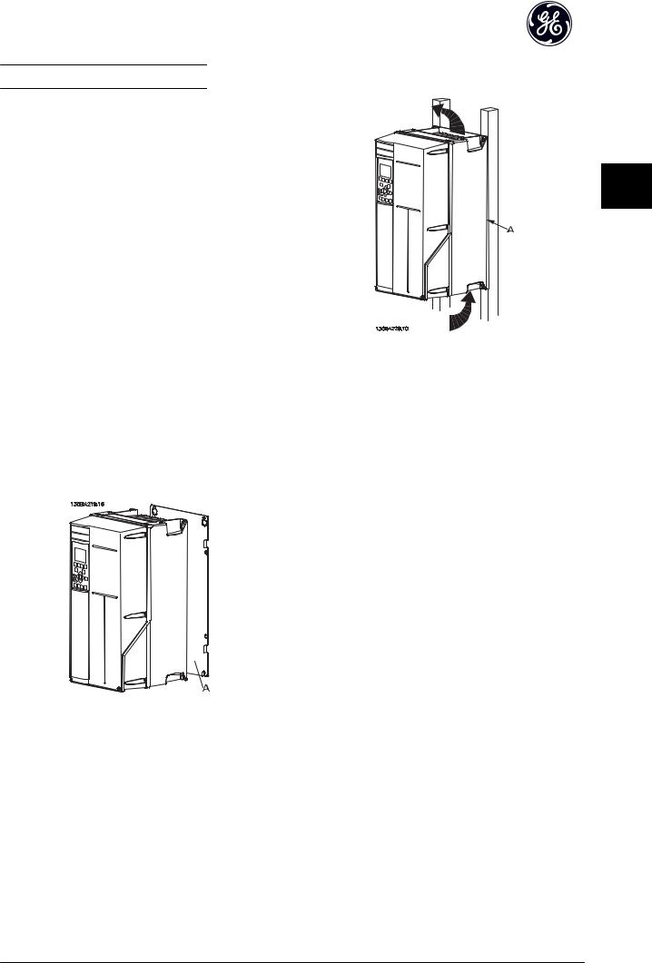
Illustration 2.3 Proper Mounting with Railings |
|
|
•Ensure that the strength of the mounting location will support the unit weight
•
•
•
Mount the unit to a solid flat surface or to the optional back plate to provide cooling airflow (see Illustration 2.2 and Illustration 2.3)
Improper mounting can result in over heating and reduced performance
Use the slotted mounting holes on the unit for wall mounting, when provided
NOTE
Back plate is needed when mounted on railings.
2.3.4 Tightening Torques
See 10.4 Connection Tightening Torques for proper tightening specifications.
Illustration 2.2 Proper Mounting with Back Plate
Item A is a back plate properly installed for required airflow to cool the unit.
9

Installation |
AF-600 FP Operating Instructions |
|
|
2.4 Electrical Installation
This section contains detailed instructions for wiring the drive. The following tasks are described.
• Wiring the motor to the drive output terminals
2 |
2 |
• |
Wiring the AC mains to the drive input terminals |
|
|
|
•Connecting control and serial communication wiring
•After power has been applied, checking input and motor power; programming control terminals for their intended functions
Illustration 2.4 shows a basic electrical connection.
Illustration 2.4 Basic Wiring Schematic Drawing.
10

Installation |
AF-600 FP Operating Instructions |
|
|
2.4.1 Requirements

 WARNING
EQUIPMENT HAZARD!
Rotating shafts and electrical equipment can be hazardous. All electrical work must conform to national and local electrical codes. It is strongly recommended that installation, start up, and maintenance be performed only by trained and qualified personnel. Failure to follow these guidelines could result in death or serious injury.
CAUTION
WIRING ISOLATION!
Run input power, motor wiring and control wiring in three separate metallic conduits or use separated shielded cable for high frequency noise isolation. Failure to isolate power, motor and control wiring could result in less than optimum drive and associated equipment performance.
For your safety, comply with the following requirements.
•Electronic controls equipment is connected to hazardous mains voltage. Extreme care should be taken to protect against electrical hazards when applying power to the unit.
•Run motor cables from multiple frequency converters separately. Induced voltage from output motor cables run together can charge equipment capacitors even with the equipment turned off and locked out.
Overload and Equipment Protection
•An electronically activated function within the drive provides overload protection for the motor. The overload calculates the level of increase to activate timing for the trip (controller output stop) function. The higher the current draw, the quicker the trip response. The overload provides Class 20 motor protection. See 8 Warnings and Alarms for details on the trip function.
•Because the motor wiring carries high frequency current, it is important that wiring for mains, motor power, and control are run separately. Use metallic conduit or separated shielded wire. Failure to isolate power, motor, and control wiring could result in less than optimum equipment performance. See Illustration 2.5.
2 2
Illustration 2.5 Proper Electrical Installation Using Conduit
•All frequency converters must be provided with short-circuit and over-current protection. Input fusing is required to provide this protection, see Illustration 2.6. See maximum fuse ratings in
10.3 Fuse Tables.
Illustration 2.6 Drive Fuses
Wire Type and Ratings
•All wiring must comply with local and national regulations regarding cross-section and ambient temperature requirements.
•GE recommends that all power connections be made with a minimum 75° C rated copper wire.
•See 10.1 Power-dependent Specifications for recommended wire sizes.
11

Installation |
AF-600 FP Operating Instructions |
|
|
2.4.2 Earth (Grounding) Requirements

 WARNING
GROUNDING HAZARD!
For operator safety, it is important to ground drive
2 2 properly in accordance with national and local electrical codes as well as instructions contained within these instructions. Ground currents are higher than 3,5mA. Failure to ground drive properly could result in death or serious injury.
NOTE
It is the responsibility of the user or certified electrical installer to ensure correct grounding (earthing) of the equipment in accordance with national and local electrical codes and standards.
•Follow all local and national electrical codes to ground electrical equipment properly
•Proper protective grounding for equipment with ground currents higher than 3,5mA must be established, see Leakage Current (>3,5mA)
•A dedicatedground wire is required for input power, motor power and control wiring
•Use the clamps provided with on the equipment for proper ground connections
•Do not ground one drive to another in a “daisy chain” fashion
•Keep the ground wire connections as short as possible
•Use of high-strand wire to reduce electrical noise is recommended
•Follow motor manufacturer wiring requirements
2.4.2.1 Leakage Current (>3,5mA)
Follow national and local codes regarding protective earthing of equipment with a leakage current > 3,5mA. Drive technology implies high frequency switching at high power. This will generate a leakage current in the earth connection. A fault current in the drive at the output power terminals might contain a DC component which can charge the filter capacitors and cause a transient earth current. The earth leakage current depends on various system configurations including RFI filtering, screened motor cables, and drive power.
EN/IEC61800-5-1 (Power Drive System Product Standard) requires special care if the leakage current exceeds 3,5mA. Earth grounding must be reinforced in one of the following ways:
•Earth ground wire of at least 10mm2
•Two separate earth ground wires both complying with the dimensioning rules
See EN 60364-5-54 § 543.7 for further information.
Using RCDs
Where residual current devices (RCDs), also known as earth leakage circuit breakers (ELCBs), are used, comply with the following:
Use RCDs of type B only which are capable of detecting AC and DC currents
Use RCDs with an inrush delay to prevent faults due to transient earth currents
Dimension RCDs according to the system configuration and environmental considerations
12
Installation |
AF-600 FP Operating Instructions |
|
|
2.4.2.2 Grounding Using Shielded Cable
Earthing (grounding) clamps are provided for motor wiring (see Illustration 2.7).
1.Use a wire stripper to remove the insulation for proper grounding.
2.Secure the grounding clamp to the stripped portion of the wire with the screws provided.
3.Secure the grounding wire to the grounding
clamp provided. |
2 |
2 |
|
|
2.4.3 Motor Connection

 WARNING
INDUCED VOLTAGE!
Run output motor cables from multiple frequency converters separately. Induced voltage from output motor cables run together can charge equipment capacitors even with the equipment turned off and locked out. Failure to run output motor cables separately could result in death or serious injury.
Illustration 2.7 Grounding with Shielded Cable
2.4.2.3 Grounding Using Conduit

 CAUTION
GROUNDING HAZARD!
Do not use conduit connected to the drive as a replacement for proper grounding. Ground currents are higher than 3.5mA. Improper grounding can result in personal injury or electrical shorts.
Dedicated grounding clamps are provided (See
Illustration 2.8).
•For maximum wire sizes see 10.1 Power-dependent Specifications
•Comply with local and national electrical codes for cable sizes
•Motor wiring knockouts or access panels are provided at the base of IP55 / Nema 12 units
•Do not install power factor correction capacitors between the drive and the motor
•Do not wire a starting or pole-changing device between the drive and the motor
•Connect the 3-phase motor wiring to terminals 96 (U), 97 (V), and 98 (W)
•Ground the cable in accordance with grounding instructions provided
•Torque terminals in accordance with the information provided in 10.4.1 Connection Tightening Torques
•Follow motor manufacturer wiring requirements
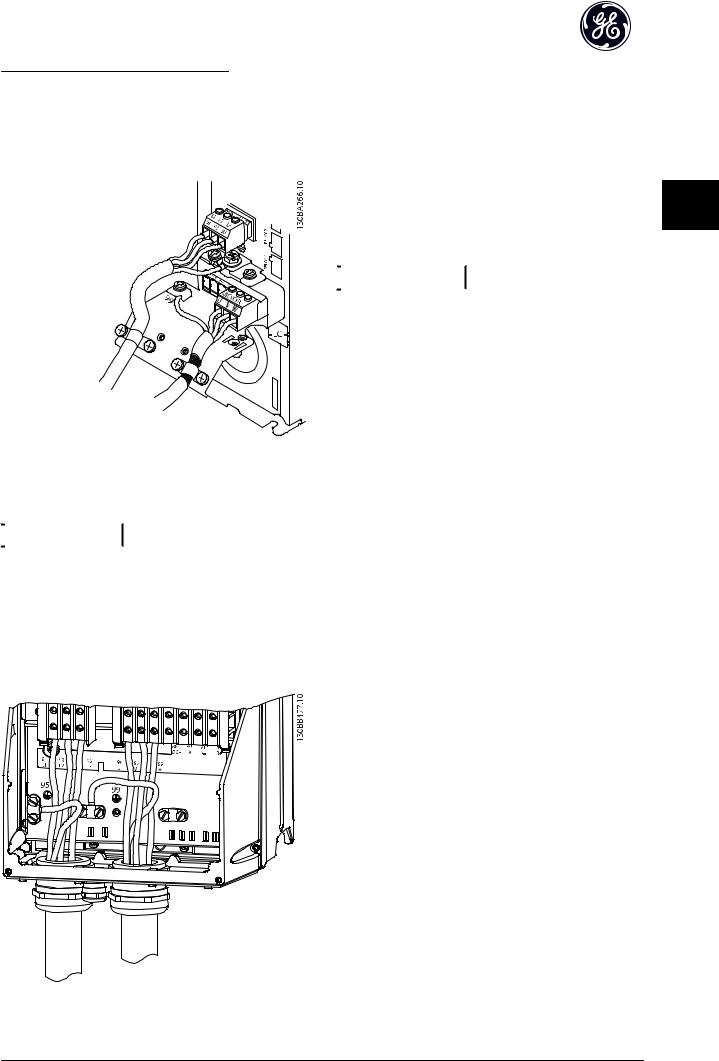
The three following illustrations represent mains input, motor, and earth grounding for basic frequency converters. Actual configurations vary with unit types and optional equipment.
Illustration 2.8 Grounding with Conduit
13

Installation |
AF-600 FP Operating Instructions |
|
|
2 2
Illustration 2.9 Motor, Mains and Earth Wiring for Frame Sizes 1X
Illustration 2.11 Motor, Mains and Earth Wiring for Frame Sizes
2X and Above Using Conduit
2.4.4 AC Mains Connection
•
•
•
•
Size wiring based upon the input current of the drive. For maximum wire sizes see 10.1 Powerdependent Specifications.
Comply with local and national electrical codes for cable sizes.
Connect 3-phase AC input power wiring to terminals L1, L2, and L3 (see Illustration 2.12).
Input power will be connected to the mains input terminals.
Illustration 2.10 Motor, Mains and Earth Wiring for Frame Sizes 2X and Above Using Shielded Cable
Illustration 2.12 Connecting to AC Mains
14
Installation |
AF-600 FP Operating Instructions |
|
|
•Ground the cable in accordance with grounding instructions provided in 2.4.2 Earth (Grounding) Requirements
•All frequency converters may be used with an isolated input source as well as with ground reference power lines. When supplied from an isolated mains source (IT mains or floating delta) or TT/TN-S mains with a grounded leg (grounded delta), set SP-50 RFI Filter to OFF. When off, the internal RFI filter capacitors between the chassis and the intermediate circuit are isolated to avoid damage to the intermediate circuit and to reduce earth capacity currents in accordance with IEC 61800-3.
2.4.5 Control Wiring
•Isolate control wiring from high power components in the drive.
•If the drive is connected to a thermistor, for PELV isolation, optional thermistor control wiring must be reinforced/double insulated. A 24 VDC supply voltage is recommended.
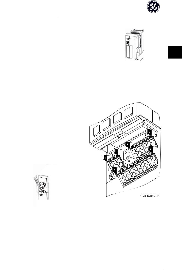
2.4.5.1 Access
•Remove access cover plate with a screw driver. See Illustration 2.13.
•Or remove front cover by loosening attaching screws. See Illustration 2.14.
Tightening torque for front cover is 2.0Nm for unit size 15 and 2.2Nm for unit sizes 2X and 3X.
2 2
130BT334.11
Illustration 2.14 Control Wiring Access for IP55 / Nema 12
enclosures
2.4.5.2 Control Terminal Types
Illustration 2.18 shows the removable drive connectors. Terminal functions and default settings are summarized in
Table 2.2.
130BT248
Illustration 2.15 Control Terminal Locations |
|
Illustration 2.13 Control Wiring Access for IP20 / Open chassis |
|
enclosures |
|
• |
Connector 1 provides four programmable digital |
|
inputs terminals, two additional digital terminals |
|
programmable as either input or output, a 24V |
|
DC terminal supply voltage, and a common for |
|
optional customer supplied 24V DC voltage |
•
•
Connector 2 terminals (+)68 and (-)69 are for an RS-485 serial communications connection
Connector 3 provides two analog inputs, one analog output, 10V DC supply voltage, and commons for the inputs and output
15
Installation |
AF-600 FP Operating Instructions |
•Connector 4 is a USB port available for use with the DCT-10
•Also provided are two Form C relay outputs that are in various locations depending upon the drive configuration and size
2 2 • Some options available for ordering with the unit may provide additional terminals. See the manual provided with the equipment option.
See 10.2 General Technical Data for terminal ratings details.
Terminal Description
Digital Inputs/Outputs
|
|
Default |
|
Terminal |
Parameter |
Setting |
Description |
12, 13 |
- |
+24V DC |
24V DC supply |
|
|
|
voltage. Maximum |
|
|
|
output current is |
|
|
|
200mA total for all |
|
|
|
24V loads. Useable for |
|
|
|
digital inputs and |
|
|
|
external transducers. |
|
|
|
|
18 |
E-01 |
[8] Start |
|
19 |
E-02 |
[0] No |
|
|
|
operation |
|
32 |
E-05 |
[0] No |
Digital inputs. |
|
|
operation |
|
33 |
E-06 |
[0] No |
|
|
|
operation |
|
27 |
E-03 |
[0] No |
Selectable for either |
|
|
operation |
digital input or |
29 |
E-04 |
[14] JOG |
output. Default setting |
|
|
|
is input. |
20 |
- |
|
Common for digital |
|
|
|
inputs and 0V |
|
|
|
potential for 24V |
|
|
|
supply. |
|
|
|
|
|
Analog Inputs/Outputs |
||
|
|
|
|
39 |
- |
|
Common for analog |
|
|
|
output |
|
|
|
|
42 |
AN-50 |
Speed 0 - |
Programmable analog |
|
|
High Limit |
output. The analog |
|
|
|
signal is 0-20mA or |
|
|
|
4-20mA at a |
|
|
|
maximum of 500Ω |
50 |
- |
+10V DC |
10V DC analog supply |
|
|
|
voltage. 15mA |
|
|
|
maximum commonly |
|
|
|
used for potenti- |
|
|
|
ometer or thermistor. |
53 |
AN-1# |
Reference |
Analog input. |
54 |
AN-2# |
Feedback |
Selectable for voltage |
|
|
|
or current. Switches |
|
|
|
A53 and A54 select |
|
|
|
mA or V. |
Terminal Description
Digital Inputs/Outputs
|
|
Default |
|
Terminal |
Parameter |
Setting |
Description |
55 |
- |
|
Common for analog |
|
|
|
input |
|
|
|
|
|
Serial Communication |
||
|
|
|
|
61 |
- |
|
Integrated RC-Filter for |
|
|
|
cable screen. ONLY for |
|
|
|
connecting the screen |
|
|
|
when experiencing |
|
|
|
EMC problems. |
|
|
|
|
68 (+) |
O-3# |
|
RS-485 Interface. A |
|
|
|
control card switch is |
69 (-) |
O-3# |
|
|
|
|
|
provided for |
|
|
|
termination resistance. |
|
|
|
|
|
|
Relays |
|
|
|
|
|
01, 02, 03 |
E-24 [0] |
[0] Alarm |
Form C relay output. |
|
|
|
Usable for AC or DC |
04, 05, 06 |
E-24 [1] |
[0] Running |
|
|
|
|
voltage and resistive |
|
|
|
or inductive loads. |
|
|
|
|
Table 2.2 Terminal Description |
|
||
2.4.5.3 Wiring to Control Terminals
Control terminal connectors can be unplugged from the drive for ease of installation, as shown in Illustration 2.16.
Illustration 2.16 Unplugging Control Terminals
1.Open the contact by inserting a small screwdriver into the slot above or below the contact, as shown in Illustration 2.17.
2.Insert the bared control wire into the contact.
3.Remove the screwdriver to fasten the control wire into the contact.
4.Ensure the contact is firmly established and not loose. Loose control wiring can be the source of equipment faults or less than optimal operation.
16

Installation |
AF-600 FP Operating Instructions |
|
|
See 10.1 Power-dependent Specifications for control terminal wiring sizes.
See 6 Application Set-Up Examples for typical control wiring connections.
Illustration 2.17 Connecting Control Wiring
2.4.5.5 Control Terminal Functions
Drive functions are commanded by receiving control input signals.
•Each terminal must be programmed for the
function it will be supporting in the parameters 2 2 associated with that terminal. SeeTable 2.2 for
terminals and associated parameters.
•It is important to confirm that the control terminal is programmed for the correct function. See 4 User Interface for details on accessing parameters and for details on programming.
•The default terminal programming is intended to initiate drive functioning in a typical operational mode.
2.4.5.4 Using Screened Control Cables
Correct screening
The preferred method in most cases is to secure control and serial communication cables with screening clamps provided at both ends to ensure best possible high frequency cable contact.
50/60Hz ground loops
With very long control cables, ground loops may occur. To eliminate ground loops, connect one end of the screen-to- ground with a 100nF capacitor (keeping leads short).
Avoid EMC noise on serial communication
To eliminate low-frequency noise between frequency converters, connect one end of the screen to terminal 61. This terminal is connected to ground via an internal RC link. Use twisted-pair cables to reduce interference between conductors.
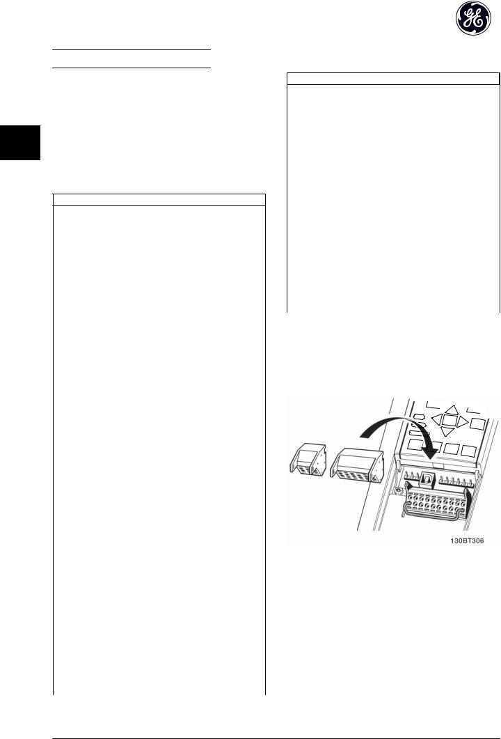
2.4.5.6 Terminal 53 and 54 Switches
•Analog input terminals 53 and 54 can select either voltage (0 to 10V) or current (0/4-20mA) input signals
•Remove power to the drive before changing switch positions
•Set switches A53 and A54 to select the signal type. U selects voltage, I selects current.
•The switches are accessible when the keypad has been removed (see Illustration 2.18). Note that some option cards available for the unit may cover these switches and must be removed to change switch settings. Always remove power to the unit before removing option cards.
•Terminal 53 default is for a speed reference signal in open loop set in DR-61 Terminal 53 Switch Setting
•Terminal 54 default is for a feedback signal in closed loop set in DR-63 Terminal 54 Switch Setting
17
|
Installation |
AF-600 FP Operating Instructions |
||
|
|
|
For basic serial communication set-up, select the following |
|
|
|
|
1. |
Protocol type in O-30 Protocol. |
|
|
|
2. |
Drive address in O-31 Address. |
2 |
2 |
|
3. |
Baud rate in O-32 Drive Port Baud Rate. |
|
• |
Four communication protocols are internal to the |
||
|
|
|
|
drive. Follow motor manufacturer wiring |
|
|
|
|
requirements. |
|
|
|
|
Drive profile |
|
|
|
|
Modbus RTU |
|
|
|
|
Metasys N2® |
|
|
|
|
Apogee FLN® |
|
|
|
• |
Functions can be programmed remotely using |
|
|
|
130BT310.10 |
the protocol software and RS-485 connection or |
|
|
|
|
|
|
Illustration 2.18 Location of Terminals 53 and 54 Switches |
in parameter group O-## Options / Comms |
||
|
|
|
• |
Selecting a specific communication protocol |
|
2.4.6 Serial Communication |
|
changes various default parameter settings to |
|
|
|
match that protocol’s specifications along with |
||
|
|
|
|
making additional protocol-specific parameters |
|
Connect RS-485 serial communication wiring to terminals |
available |
||
|
(+)68 and (-)69. |
• |
Option cards which install into the drive are |
|
|
|
|
||
|
• |
Screened serial communication cable is |
available to provide additional communication |
|
|
protocols. See the option-card documentation for |
|||
|
|
recommended |
|
installation and operation instructions |
•See 2.4.2 Earth (Grounding) Requirements for proper grounding
Illustration 2.19 Serial Communication Wiring Diagram
18

Start Up and Functional Tes... |
AF-600 FP Operating Instructions |
|
|
3 Start Up and Functional Testing
3.1 Pre-start |
|
|
|
3.1.1 Safety Inspection |
|
|
|
|
|
3 |
3 |
WARNING |
|
||
|
|
|
|
HIGH VOLTAGE! |
|
|
|
If input and output connections have been connected improperly, there is potential for high voltage on these terminals. If power leads for multiple motors are improperly run in same conduit, there is potential for leakage current to charge capacitors within the drive, even when disconnected from mains input. For initial start up, make no assumptions about power components. Follow pre-start procedures. Failure to follow pre-start procedures could result in personal injury or damage to equipment.
1.Input power to the unit must be OFF and locked out. Do not rely on the drive disconnect switches for input power isolation.
2.Verify that there is no voltage on input terminals L1 (91), L2 (92), and L3 (93), phase-to-phase and phase-to-ground,
3.Verify that there is no voltage on output terminals 96 (U), 97 (V), and 98 (W), phase-to- phase and phase-to-ground.
4.Confirm continuity of the motor by measuring ohm values on U-V (96-97), V-W (97-98), and W-U (98-96).
5.Check for proper grounding of the drive as well as the motor.
6.Inspect the drive for loose connections on terminals.
7.Record the following motor-nameplate data: power, voltage, frequency, full load current, and nominal speed. These values are needed to program motor nameplate data later.
8.Confirm that the supply voltage matches voltage of drive and motor.
19

Start Up and Functional Tes... |
AF-600 FP Operating Instructions |
|
|
3.1.2 Start Up Check List
CAUTION
Before applying power to the unit, inspect the entire installation as detailed in Table 3.1. Check mark those items when completed.
|
Inspect for |
Description |
|
|
3 3 |
Auxiliary equipment |
• |
Look for auxiliary equipment, switches, disconnects, or input fuses/circuit |
|
|
|
breakers that may reside on input power side of drive or output side to motor. |
|
|
|
|
|
Examine their operational readiness and ensure that they are ready in all |
|
|
|
|
respects for operation at full speed. |
|
|
|
• |
Check function and installation of any sensors used for feedback to drive |
|
|
|
• |
Remove power factor correction caps on motor(s), if present |
|
|
|
|
|
|
|
Cable routing |
• |
Ensure that input power, motor wiring, and control wiring are separated or in |
|
|
|
|
three separate metallic conduits for high frequency noise isolation |
|
|
|
|
|
|
|
Control wiring |
• |
Check for broken or damaged wires and loose connections |
|
|
|
• |
Check that control wiring is isolated from power and motor wiring for noise |
|
|
|
|
immunity |
|
|
|
• |
Check the voltage source of the signals, if necessary |
|
|
|
• |
The use of shielded cable or twisted pair is recommended. Ensure that the |
|
|
|
|
shield is terminated correctly. |
|
|
|
|
|
|
|
Cooling clearance |
• |
Measure that top and bottom clearance is adequate to ensure proper air flow |
|
|
|
|
for cooling |
|
|
|
|
|
|
|
EMC considerations |
• |
Check for proper installation regarding electromagnetic compatibility |
|
|
|
|
|
|
|
Environmental considerations |
• |
See equipment label for the maximum ambient operating temperature limits |
|
|
|
• |
Humidity levels must be 5-95% non-condensing |
|
|
|
|
|
|
|
Fusing and circuit breakers |
• |
Check for proper fusing or circuit breakers |
|
|
|
• |
Check that all fuses are inserted firmly and in operational condition and that all |
|
|
|
|
circuit breakers are in the open position |
|
|
|
|
|
|
|
Grounding |
• |
The unit requires a ground wire from its chassis to the building ground |
|
|
|
• |
Check for good ground connections that are tight and free of oxidation |
|
|
|
• |
Grounding to conduit or mounting the back panel to a metal surface is not a |
|
|
|
|
suitable ground |
|
|
|
|
|
|
|
Input and output power wiring |
• |
Check for loose connections |
|
|
|
• |
Check that motor and mains are in separate conduit or separated screened |
|
|
|
|
cables |
|
|
|
|
|
|
|
Panel interior |
• |
Inspect that the unit interior is free of dirt, metal chips, moisture, and corrosion |
|
|
|
|
|
|
|
Switches |
• |
Ensure that all switch and disconnect settings are in the proper position |
|
|
|
|
|
|
|
Vibration |
• |
Check that the unit is mounted solidly or that shock mounts are used, as |
|
|
|
|
necessary |
|
|
|
• |
Look for any unusual amount of vibration the unit may be subjected to |
|
|
|
|
|
|
Table 3.1 Start Up Check List
20

Start Up and Functional Tes... |
AF-600 FP Operating Instructions |
|
|
3.2 Applying Power to the Drive

 WARNING
HIGH VOLTAGE!
Frequency converters contain high voltage when connected to AC mains. Installation, start-up and maintenance should be performed by qualified personnel only. Failure to perform installation, start-up and maintenance by qualified personnel could result in death or serious injury.

 WARNING
UNINTENDED START!
4.Select language and press [OK]. Then enter the motor data in parameters P-02, P-03, P-06, P-07, F-04 and F-05. The information can be found on the motor nameplate. The entire quick menu is shown in 5.5.1 Quick Menu Structure
P-07 Motor Power [kW] or P-02 Motor 3 3 Power [HP]
F-05 Motor Rated Voltage
F-04 Base Frequency
P-03 Motor Current
P-06 Base Speed
When drive is connected to AC mains, the motor may start at any time. The drive, motor, and any driven equipment must be in operational readiness. Failure to be in operational readiness when the drive is connected to AC mains could result in death, serious injury, equipment, or property damage.
1.Confirm input voltage is balanced within 3%. If not, correct input voltage imbalance before proceeding. Repeat procedure after voltage correction.
2.Ensure optional equipment wiring, if present, matches installation application.
3.Ensure that all operator devices are in the OFF position. Panel doors closed or cover mounted.
4.Apply power to the unit. DO NOT start the drive at this time. For units with a disconnect switch, turn to the ON position to apply power to the drive.
3.3Basic Operational Programming
Drives require basic operational programming prior to running for best performance. Basic operational programming requires entering motor-nameplate data for the motor being operated and the minimum and maximum motor speeds. Enter data in accordance with the following procedure. Parameter settings recommended are intended for start up and checkout purposes. Application settings may vary. See 4 User Interface for detailed instructions on entering data through the keypad.
Enter data with power ON, but prior to operating the drive.
1.Press [Quick Menu] on the keypad.
3.Use the navigation keys to scroll to Quick Start and press [OK].
5.F-07 Accel Time 1 is recommended as 60 seconds for fans or 10 seconds for pumps.
6.F-08 Decel Time 1 is recommended as 60 seconds for fans or 10 seconds for pumps.
7.For F-10 enter Elec OL Trip 1 for Class 20 overload protection. For further information, please see 2.4.1 Requirements
8.For F-16 Motor Speed Low Limit [Hz] enter the application requirements. If these values are unknown at this time, the following values are recommended. These values will ensure initial drive operation. However, take any precautions necessary to prevent equipment damage. Make sure that the recommended values are safe to use for functional testing before starting the equipment.
Fan = 20Hz
Pump = 20Hz
Compressor = 30Hz
9.In F-15 Motor Speed High Limit [Hz] enter the motor frequency from F-04 Base Frequency.
This concludes the quick set-up procedure. Press [Status] to return to the operational display.
In P-04 Auto Tune select Reduced Auto Tune or Full Auto Tune and follow on-screen instructions. See 3.4 Auto Tune
3.4 Auto Tune
Auto tune is a test procedure that measures the electrical characteristics of the motor to optimize compatibility between the drive and the motor.
•The drive builds a mathematical model of the motor for regulating output motor current. The procedure also tests the input phase balance of electrical power. It compares the motor character-
21

Start Up and Functional Tes... |
AF-600 FP Operating Instructions |
|
|
|
|
|
istics with the data entered in P-02, P-03, P-06, |
|
|
|
P-07, F-04 and F-05. |
|
|
• |
It does not cause the motor to run or harm to |
|
|
|
the motor |
|
|
• |
Some motors may be unable to run the complete |
|
|
|
version of the test. In that case, select Reduced |
|
|
|
Auto Tune |
3 |
3 |
• |
If an output filter is connected to the motor, |
|
select Reduced Auto Tune |
•If warnings or alarms occur, see 8 Warnings and Alarms
•Run this procedure on a cold motor for best results
3.5Check Motor Rotation
Prior to running the drive, check the motor rotation. The motor will run briefly at 5Hz or the minimum frequency set in F-16 Motor Speed Low Limit [Hz].
1.Press [Main Menu] twice on the keypad.
2.Enter Parameter Data Set and scroll to P-## Motor Data and press [OK] to enter.
3.Scroll to P-08 Motor Rotation Check.
4.Press [OK].
5.Scroll to Enable.
The following text will appear: Note! Motor may run in wrong direction.
6.Press [OK].
7.Follow the on-screen instructions.
To change the direction of rotation, remove power to the drive and wait for power to discharge. Reverse the connection of any two of the three motor cables on the motor or drive side of the connection.
NOTE
The hand key on the keypad provides a local start command to the drive. The OFF key provides the stop function.
When operating in local mode, the up and down arrows on the keypad increase and decrease the speed output of the drive. The left and right arrow keys move the display cursor in the numeric display.
1.Press [Hand].
2.Accelerate the drive by pressing [▲] to full speed. Moving the cursor left of the decimal point provides quicker input changes.
3.Note any acceleration problems.
4.Press [OFF].
5.Note any deceleration problems.
If acceleration problems were encountered
•If warnings or alarms occur, see 8 Warnings and Alarms
•Check that motor data is entered correctly
•Increase the accel time in F-07 Accel Time 1
•Increase current limit in F-43 Current Limit
•Increase torque limit in F-40 Torque Limiter (Driving)
If deceleration problems were encountered
•If warnings or alarms occur, see 8 Warnings and Alarms
•Check that motor data is entered correctly
•Increase the decel time in F-08 Decel Time 1
See 8.4 Warning and Alarm Definitions for resetting the drive after a trip.
3.6 Local-control Test

 CAUTION
MOTOR START!
Ensure that the motor, system, and any attached equipment is ready for start. It is the responsibility of the user to ensure safe operation under any operational condition. Failure to ensure that the motor, system, and any attached equipment is ready for start could result in personal injury or equipment damage.
NOTE
3.1 Pre-start through 3.6 Local-control Test in this chapter concludes the procedures for applying power to the drive, basic programming, set-up, and functional testing.
22

Start Up and Functional Tes... AF-600 FP Operating Instructions
3.7 System Start Up
The procedure in this section requires user-wiring and application programming to be completed. is intended to help with this task. Other aids to application set-up are listed in 1.2 Additional Resources. The following procedure is recommended after application set-up by the user is completed.
|
3 3 |
CAUTION |
MOTOR START!
Ensure that the motor, system, and any attached equipment is ready for start. It is the responsibility of the user to ensure safe operation under any operational condition. Failure to ensure that the motor, system, and any attached equipment is ready for start could result in personal injury or equipment damage.
1.Press [Auto].
2.Ensure that external control functions are properly wired to the drive and all programming completed.
3.Apply an external run command.
4.Adjust the speed reference throughout the speed range.
5.Remove the external run command.
6.Note any problems.
If warnings or alarms occur, see 8 Warnings and Alarms.
23
User Interface |
AF-600 FP Operating Instructions |
|
|
4 User Interface
4.1 Keypad
The keypad is the combined display and keys on the front of the unit. The keypad is the user interface to the frequency converter.
The keypad has several user functions.
4 4 • Start, stop, and control speed when in local control
•Display operational data, status, warnings and cautions
•Programming frequency converter functions
•Manually reset the frequency converter after a fault when auto-reset is inactive
NOTE
The display contrast can be adjusted by pressing [STATUS] and the up/ down key.
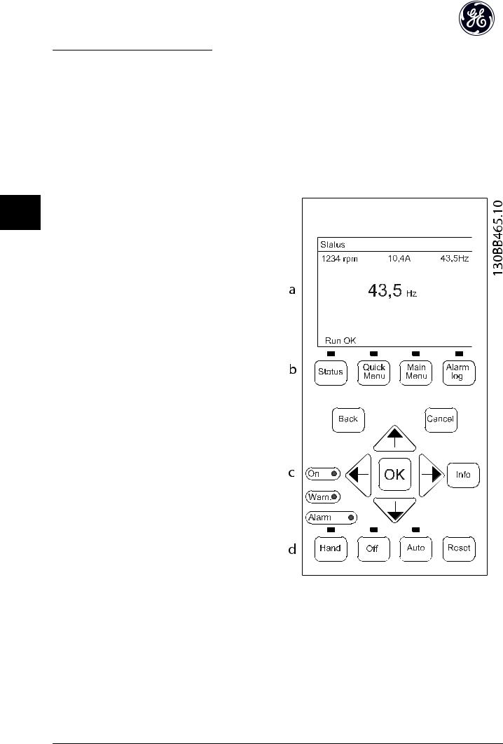
4.1.1 Keypad Layout
The keypad is divided into four functional groups (see
Illustration 4.1).
Illustration 4.1 Keypad
a.Display area.
b.Display menu keys for changing the display to show status options, programming, or error message history.
c.Navigation keys for programming functions, moving the display cursor, and speed control in local operation. Also included are the status indicator lights.
d.Operational mode keys and reset.
24
 Loading...