


 Loading...
GE Consumer & Industrial
ASTAT XT
User Manual

2 •Warnings
WARNINGS
1.DISCONNECT POWER BEFORE INSTALLING OR SERVICING.
2.HAZARDOUS VOLTAGES ARE PRESENT IN THE MOTOR CIRCUIT EVEN WHEN THE STARTER IS OFF. AN ISOLATION CONTACTOR IS RECOMMENDED, CONFIGURED TO PROVIDE AUTOMATIC ISOLATION WHEN THE MOTOR IS TURNED OFF.
3.UNIT MAY CONTAIN MORE THAN ONE LIVE CIRCUIT. DISCONNECT BOTH CONTROL AND MAIN CIRCUITS BEFORE INSTALLING OR SERVICING.
4.SOFT STOP SHOULD NOT BE USED AS AN EMERGENCY STOP.
5.STOPPING MODE MUST BE SET TO MEET APPLICABLE STANDARDS FOR OPERATOR SAFETY.
6.SEPARATE MOTOR OVERCURRENT PROTECTION IS REQUIRED TO BE PROVIDED IN ACCORDANCE WITH THE CANADIAN ELECTRICAL CODE, PART 1. ASTAT-XT PROVIDES SEPARATE MOTOR PROTECTION.
 CAUTIONS
1.SEMI-CONDUCTOR FUSES SPECIFIED MAY NOT PROVIDE BRANCH CIRCUIT PROTECTION. REFER TO LOCAL APPLICABLE ELECTRICAL CODES.
2.OVERLOAD RELAY SETTING SHOULD BE PROPERLY COORDINATED WITH MOTOR.
3.SLOW SPEED RUNNING WILL AFFECT THE MOTOR THERMAL CHARACTERISTIC DUE TO REDUCED COOLING.
CARE MUST BE TAKEN WHEN OPERATING MOTOR UNDER THESE CONDITIONS.
4.ABNORMAL STARTING TIMES IN EXCESS OF 30 SECONDS, OR CLOSELY REPEATED OPERATIONS OF ACCELERATION RAMP/DECELERATION RAMP, SLOW SPEED, MAY CAUSE MOTOR DAMAGE. CONTACT MOTOR MANUFACTURER FOR PROPER MOTOR SELECTION.
5.IF CONTROL POWER IS LOST BETWEEN STARTS, THE OVERLOAD RELAY PROTECTION IS RESET TO COLD START CONDITIONS.
REMARKS:
1.Read this manual thoroughly before using the ASTAT-XT and store in a safe place for reference.
2.Make sure that this manual is delivered to the end user.
3.The policy of GE Industrial Systems is one of continuous improvement.
The right is reserved to alter the design on any structural details of the products at any time without giving notice.

3 • Table of Contents
ASTAT-XT User Manual |
|
|||
1. |
Generalities..................................................................................................................................................... |
7 |
||
1.1 |
Squirrel-Cage Motor Starting.................................................................................................................................................... |
7 |
||
1.2 |
Advantages of the ASTAT-XT Solid State Soft Starters................................................................................................. |
7 |
||
2. |
Types and Ratings ......................................................................................................................................... |
8 |
||
2.1 |
IEC Ratings. Recommended Motor and Type Unit Ratings........................................................................................ |
8 |
||
2.2 |
NEMA Ratings . Recommended Motor and Type Unit Ratings................................................................................. |
9 |
||
2.3 |
Thermal Characteristics ............................................................................................................................................................ |
10 |
||
3. |
Technical Specifications ............................................................................................................................. |
11 |
||
3.1 |
General Specifications ............................................................................................................................................................... |
11 |
||
3.2 |
Weight |
................................................................................................................................................................................................ |
|
13 |
3.3 |
I/O Terminal Board Specifications........................................................................................................................................ |
13 |
||
3.4 |
I/O Wiring.......................................................................................................................................................................................... |
|
17 |
|
3.5 |
Ordering ..................................................................................................................................................................Information |
18 |
||
3.6 |
3.5.1 ................................................................................................................................................. |
Ordering Accessories |
18 |
|
Operating ..........................................................................................................................................................................Modes |
19 |
|||
4. |
Control .............................................................................................................................................Keypad |
20 |
||
4.1 |
LCD Arrangement......................................................................................................................................................................... |
20 |
||
4.2 |
Push-Buttons .................................................................................................................................................................................. |
21 |
||
4.3 |
Status LEDs...................................................................................................................................................................................... |
|
21 |
|
4.4 |
Reviewing ...............................................................................................................................and Modifying Parameters |
21 |
||
4.5 |
Special .............................................................................................Actions Performed in Test/Maintenance Mode |
22 |
||
|
4.5.1 ................................................................................................................................................................... |
Run Self Test |
22 |
|
|
4.5.2 ............................................................................................................................................... |
View Software Version |
22 |
|
|
4.5.3 ..................................................................................................................................... |
Obtain Default Parameters |
22 |
|
|
4.5.4 ................................................................................................................................................. |
Reset Statistical Data |
22 |
|
4.6 |
4.5.5 ..................................................................................... |
Calibrate Voltage and Current (Factory Use Only!) |
23 |
|
Mode Pages..................................................................................................................................................................................... |
|
23 |
||
4.7 |
Overview ......................................................................................................of All Mode Pages and Factory Defaults |
24 |
||
|
4.7.1 .............................................................................................................................................. |
Display Mode – Page 0 |
26 |
|
|
4.7.2 .............................................................................................................................................. |
Main Settings – Page 1 |
27 |
|
|
4.7.3 .............................................................................................................................................. |
Start Settings – Page 2 |
29 |
|
|
4.7.3.1 ....................................................................................................................................... |
Soft Start Parameters |
32 |
|
|
4.7.4 ............................................................................................................................................... |
Stop Settings – Page 3 |
34 |
|
|
4.7.4.1 ....................................................................................................................................... |
Soft Stop Parameters |
35 |
|
|
4.7.5 ................................................................................................................... |
DUAL Settings Parameters – Page 4 |
36 |
|
|
4.7.6 ........................................................................................ |
Slow Speed & Energy Save Parameters – page 5 |
37 |
|
|
4.7.7 .............................................................................................................................................. |
Fault Settings – Page 6 |
38 |
|
|
4.7.8 ........................................................................................................................ |
I/O Settings Parameters – Page 7 |
40 |
|
|
4.7.8.1 ..................................................................................................................Terminal 7 and 8 Programming |
41 |
||
|
4.7.9 .......................................................... |
COMM. Parameters – Page 8 – With the Modbus standard PCB |
42 |
|
|
4.7.10 ............................................................ |
Comm. Parameters – Page 8 – With the Profibus optional PCB |
42 |
|
|
4.7.11 ...................................................... |
Comm. Parameters – Page 8 – With the DeviceNet Optional PCB |
43 |
|
4.8 |
4.7.12 ...........................................................................................................................................Statistical Data – page 9 |
44 |
||
Non Adjustable .....................................................................................................................Protection and Fault Reset |
45 |
|||
|
4.8.1 ............................................................................................................................................. |
Under/Over Frequency |
45 |
|
|
4.8.2 ....................................................................................................................................................................... |
Phase Loss |
45 |
|
|
4.8.3 ........................................................................................................................................................... |
Phase Sequence |
45 |
|
|
4.8.4 ...................................................................................................................................................... |
Wrong Connection |
45 |
|
|
4.8.5 .................................................................................................................................................................... |
Shorted SCR |
45 |
|
|
4.8.6 ................................................................................................................................. |
Heat - Sink Over Temperature |
45 |
|
|
4.8.7 ................................................................................................................................................................. |
External Fault |
45 |
|
|
4.8.8 ............................................................................................................................................................. |
Fault and Reset |
45 |
|
4.9 |
4.8.9 ........................................................................................................................................................................ |
Auto Reset |
46 |
|
Timing ..........................................................................................................................................................Occurrence Table |
46 |
|||

4 • Table of Contents
5. |
|
Installation |
.................................................................................................................................................... |
47 |
|
5.1 |
Prior to Installation....................................................................................................................................................................... |
47 |
|||
5.2 |
Mounting........................................................................................................................................................................................... |
|
47 |
||
5.3 |
Temperature Range & Heat Dissipation............................................................................................................................ |
47 |
|||
5.4 |
|
5.3.1 |
Forced Ventilation........................................................................................................................................................ |
48 |
|
Main PCB and Optional PCBs.................................................................................................................................................. |
48 |
||||
5.5 |
Dip Switch Settings on the Main PCB.................................................................................................................................. |
49 |
|||
|
|
5.5.1 Switch # 1 – Display Modes .................................................................................................................................... |
49 |
||
|
|
5.5.2 Switch # 2 – Not used ................................................................................................................................................ |
50 |
||
|
|
5.5.3 Switch # 3 – Main/ D.Set: Generator Parameters......................................................................................... |
50 |
||
|
|
5.5.4 Switches # 5, 6 – Language Selection................................................................................................................ |
50 |
||
|
|
5.5.5 Switch # 7 – Expanded Settings............................................................................................................................ |
50 |
||
5.6 |
|
5.5.6 Switch # 8 – Software Lock ..................................................................................................................................... |
50 |
||
Internal Fan Control .................................................................................................................................................................... |
51 |
||||
5.7 |
Analog I/O (Terminals T1, T2, Gnd, Out (-), Out (+)) ........................................................................................................ |
51 |
|||
5.8 |
Remote Key-Pad Installation.................................................................................................................................................. |
52 |
|||
6. |
|
Starting Procedure ...................................................................................................................................... |
53 |
||
6.1 |
Standard Starting Procedure.................................................................................................................................................. |
54 |
|||
6.2 Examples of Starting Curves................................................................................................................................................... |
55 |
||||
|
|
6.2.1 |
Light Loads - Pumps, Etc. ......................................................................................................................................... |
55 |
|
|
|
6.2.2 High Inertia Loads: Crushers, Centrifuges, Mixers, Etc............................................................................... |
55 |
||
|
|
6.2.3 Special Starting Using DUAL Settings ................................................................................................................ |
56 |
||
|
|
6.2.3.1 Special Starting – Using DUAL Settings – Wiring Diagram ............................................................ |
57 |
||
|
|
6.2.4 Choosing a Suitable Pump Curve (Centrifugal Pumps).............................................................................. |
57 |
||
|
|
6.2.4.1 |
Starting Curve ...................................................................................................................................................... |
57 |
|
|
|
6.2.4.2 |
Stopping Curve.................................................................................................................................................... |
58 |
|
|
|
6.2.4.3 End Torque During Soft-Stopping a Pump Motor............................................................................... |
58 |
||
7. |
|
Trouble Shooting.......................................................................................................................................... |
59 |
||
8. |
|
Application diagrams.................................................................................................................................. |
62 |
||
8.1 |
Terminal 21 Connections With Various Mains................................................................................................................ |
62 |
|||
8.2 |
Control Supply, Control Input and Mains are From the Same Source, Neutral Connected to Terminal 21 |
||||
8.3 |
63 |
|
|
|
|
Control Supply and Control Input From the Same Source, Neutral not Connected to Terminal 21.... |
63 |
||||
8.4 |
Control Supply and Control Input from Separate Sources ...................................................................................... |
64 |
|||
8.5 |
Soft Start, Soft Stop and Stop, Control Supply and Control Input from the Same Source........................ |
64 |
|||
8.6 |
Soft Start, Soft Stop and Stop, Control Supply and Control Input from Separate Sources ...................... |
64 |
|||
8.7 |
Soft Start and Immediate Stop (no Soft Stop)................................................................................................................. |
65 |
|||
8.8 |
Soft Start and Soft Stop ............................................................................................................................................................. |
65 |
|||
8.9 |
Soft Start, Soft Stop and Immediate Stop......................................................................................................................... |
65 |
|||
8.10 Energy Save, Slow Speed or Reset................................................................................................................................. |
66 |
||||
8.11 Slow Speed and Slow Speed Reverse ........................................................................................................................... |
66 |
||||
8.12 |
External Fault............................................................................................................................................................................ |
67 |
|||
8.13 |
Line Contactor.......................................................................................................................................................................... |
67 |
|||
8.14 |
Bypass Contactor................................................................................................................................................................... |
68 |
|||
8.15 Reversing with Two Line Contactors............................................................................................................................. |
69 |
||||
8.16 Operating via Communication Links............................................................................................................................. |
70 |
||||
8.17 D.Set: Generator Parameters Wiring............................................................................................................................. |
71 |
||||
8.18 |
Short Circuit Protection........................................................................................................................................................ |
72 |
|||
|
|
8.18.1 Type 1 Coordination ................................................................................................................................................... |
72 |
||
|
|
8.18.1.1 Type 1 Coordination with GE Circuit Breakers: .................................................................................... |
72 |
||
|
|
8.18.1.2 Type 1 Coordination with Type aM Siba Fuses:................................................................................... |
72 |
||
8.19 |
8.18.2 Type 2 Coordination ................................................................................................................................................... |
72 |
|||
Transient Protection .............................................................................................................................................................. |
73 |
||||
8.20 |
Inside Delta Configuration.................................................................................................................................................. |
74 |
|||
|
|
8.20.1 General Information ................................................................................................................................................... |
74 |
||
|
|
8.20.2 Notes on Inside Delta Connection ....................................................................................................................... |
74 |
||
|
|
8.20.3 Motor Connection and Terminals......................................................................................................................... |
75 |
||

|
|
5 • Table of Contents |
|
|
8.20.4 ASTAT-XT Connected Inside Delta w/Bypass Contactor and Inside Delta Contactor |
................76 |
|
|
8.20.5 ASTAT-XT Connected Inside Delta - Reverse Speed.................................................................................... |
77 |
|
9. |
Dimensions.................................................................................................................................................... |
78 |
|
9.1 |
UL cUL Approved Models.......................................................................................................................................................... |
78 |
|
9.2 |
Non UL cUL Approved Models................................................................................................................................................ |
82 |
|
Appendix A - MODBUS RTU Protocol...................................................................................................................... |
86 |
||
A.1. Introduction..................................................................................................................................................................................... |
86 |
||
A.2. Basic Structure of the Serial Link Frame ........................................................................................................................... |
87 |
||
A.3. SYNC (Silent Interval) ................................................................................................................................................................... |
87 |
||
A.4. Serial Link No. (Slave Address)............................................................................................................................................... |
87 |
||
A.5. Function ............................................................................................................................................................................................ |
87 |
||
A.6. List of Functions Supported By The ASTAT-XT ............................................................................................................... |
87 |
||
A.7. Actual Data (3X References & 4X References)................................................................................................................ |
89 |
||
A.8. Parameter Settings (4X References).................................................................................................................................... |
91 |
||
A.9. Control Register Write (4X Reference) ................................................................................................................................ |
94 |
||
A.10. |
Discrete Commands (Coils, 0x References)............................................................................................................... |
95 |
|
A.11. |
Discrete Hardwired Inputs (1x References)............................................................................................................... |
97 |
|
A.12. |
Diagnostics ................................................................................................................................................................................ |
98 |
|
A.13. |
Exception Responses ............................................................................................................................................................ |
99 |
|
Appendix B - Profibus.............................................................................................................................................. |
101 |
||
B.1. Operation Mode in PROFIBUS:............................................................................................................................................. |
101 |
||
|
B.1.1. Structure of the ASTAT-XT Receiving Frame................................................................................................ |
101 |
|
|
B.1.2. Structure of the ASTAT-XT Transmitting Frame ......................................................................................... |
101 |
|
|
|
B.1.2.1. Selection of the DPV0 Registers through Data Request (DPV1)................................................ |
101 |
|
B.1.3. Read and Write from Random Registers via Data Request ................................................................. |
102 |
|
B.2. Configure the PROFIBUS in the ASTAT-XT...................................................................................................................... |
103 |
||
B.3. Watch Dog Definition .............................................................................................................................................................. |
103 |
||
B.4. Actual Data Register Numbers (decimal)....................................................................................................................... |
104 |
||
B.5. Setting Parameters Registers for Data Request......................................................................................................... |
106 |
||
Appendix C - DeviceNet™ to Modbus™ Gateway.............................................................................................. |
108 |
||
C.1. Introduction.................................................................................................................................................................................. |
108 |
||
|
C.1.1. Overview........................................................................................................................................................................ |
108 |
|
|
C.1.2. Definitions..................................................................................................................................................................... |
108 |
|
|
C.1.3. Reference Documents ............................................................................................................................................ |
108 |
|
|
C.1.4. Open DeviceNet Vendor Association, Inc. (ODVA) ..................................................................................... |
108 |
|
|
C.1.5. Rotary Switch Configuration ............................................................................................................................... |
109 |
|
|
C.1.6. LED Indicators............................................................................................................................................................. |
109 |
|
C.2. Identity Object (01HEX - 1 Instance) ..................................................................................................................................... |
111 |
||
|
C.2.1. Class Attributes (Instance 0)................................................................................................................................. |
111 |
|
|
C.2.2. Instance Attributes (Instance 1) ......................................................................................................................... |
111 |
|
|
C.2.3. Common Services ..................................................................................................................................................... |
111 |
|
C.3. Message Router Object (02HEX - 1 Instance) ................................................................................................................... |
111 |
||
C.4. DeviceNet Object (03HEX - 1 Instance)................................................................................................................................ |
111 |
||
|
C.4.1. Class Attributes (Instance 0)................................................................................................................................. |
111 |
|
|
C.4.2. Instance Attributes (Instance 1) ......................................................................................................................... |
111 |
|
|
C.4.3. Common Services ..................................................................................................................................................... |
111 |
|
C.5. Assembly Object (04HEX – 4 Instances) ............................................................................................................................ |
112 |
||
|
C.5.1. Class Attributes (Instance 0)................................................................................................................................. |
112 |
|
|
C.5.2. Output (O2T) Instance Attributes – Register 40752 .................................................................................. |
112 |
|
|
|
C.5.2.1. Output Instance 112 (0x70) – Control Output.................................................................................... |
112 |
|
C.5.3. Input (T20) Instance Attributes – Register 40257....................................................................................... |
112 |
|
|
|
C.5.3.1. Input Instance 60 (0x3C) – Basic Softstart Input .............................................................................. |
112 |
|
|
C.5.3.2. Input Instance 61 (0x3D) – Extended Softstart Input ..................................................................... |
112 |
|
|
C.5.3.3. Input Instance 100 (0x64) – Status ......................................................................................................... |
112 |
|
C.5.4. Common Services ..................................................................................................................................................... |
113 |
|
C.6. Connection Object (05HEX – 2 Instances) .......................................................................................................................... |
113 |
||

|
|
6 • Table of Contents |
|
C.6.1. Class Attributes (Instance 0)................................................................................................................................. |
113 |
||
C.6.2. Instance Attributes (Instances 1-2) Explicit, Polled I/O............................................................................ |
113 |
||
C.6.3. Common Services ..................................................................................................................................................... |
115 |
||
C.7. Softstart Object (2DHEX - 1 Instance)................................................................................................................................... |
115 |
||
C.7.1. Class Attributes (Instance 0)................................................................................................................................. |
115 |
||
C.7.2. Instance Attributes (Instance 1) ......................................................................................................................... |
115 |
||
|
C.7.2.1. Extended AtReference Values................................................................................................................... |
115 |
|
|
C.7.2.2. Extended StartMode Values....................................................................................................................... |
115 |
|
C.7.3. Common Services ..................................................................................................................................................... |
115 |
||
C.8. Control Supervisor Object (29HEX - 1 Instances) ............................................................................................................ |
115 |
||
C.8.1. Class Attributes (Instance 0)................................................................................................................................. |
115 |
||
C.8.2. Instance Attributes (Instance 1) ......................................................................................................................... |
115 |
||
C.8.3. Common Services ..................................................................................................................................................... |
116 |
||
C.9. Modbus / Serial Object (65HEX – 1 Instance).................................................................................................................... |
116 |
||
C.9.1. Class Attributes (Instance 0)................................................................................................................................. |
116 |
||
C.9.2. Instance Attributes (Instance 1) ......................................................................................................................... |
116 |
||
C.9.3. Common Services ..................................................................................................................................................... |
117 |
||
C.10. |
Input Object (70HEX – 1 Instance) .................................................................................................................................... |
117 |
|
C.10.1. |
Class Attributes (Instance 0) ............................................................................................................. |
117 |
|
C.10.2. |
Instance Attributes (Instance 1) ...................................................................................................... |
117 |
|
C.10.3. |
Common Services.................................................................................................................................. |
118 |
|
C.11. |
Main Parameter Object (71HEX – 1 Instance)............................................................................................................. |
118 |
|
C.11.1. |
Class Attributes (Instance 0) ............................................................................................................. |
118 |
|
C.11.2. |
Instance Attributes (Instance 1) ...................................................................................................... |
118 |
|
C.11.3. |
Common Services.................................................................................................................................. |
119 |
|
C.12. |
Start Settings Object (72HEX – 1 Instance)................................................................................................................... |
119 |
|
C.12.1. |
Class Attributes (Instance 0) ............................................................................................................. |
119 |
|
C.12.2. |
Instance Attributes (Instance 1) ...................................................................................................... |
119 |
|
C.12.3. |
Common Services.................................................................................................................................. |
119 |
|
C.13. |
Stop Settings Object (73HEX – 1 Instance) ................................................................................................................... |
119 |
|
C.13.1. |
Class Attributes (Instance 0) ............................................................................................................. |
119 |
|
C.13.2. |
Instance Attributes (Instance 1) ...................................................................................................... |
119 |
|
C.13.3. |
Common Services.................................................................................................................................. |
119 |
|
C.14. |
Dual Settings Object (74HEX – 1 Instance) ................................................................................................................... |
119 |
|
C.14.1. |
Class Attributes (Instance 0) ............................................................................................................. |
119 |
|
C.14.2. |
Instance Attributes (Instance 1) ...................................................................................................... |
120 |
|
C.14.3. |
Common Services.................................................................................................................................. |
120 |
|
C.15. Slow SP & Saving Parameters Object (75HEX – 1 Instance)................................................................................. |
120 |
||
C.15.1. |
Class Attributes (Instance 0) ............................................................................................................. |
120 |
|
C.15.2. |
Instance Attributes (Instance 1) ...................................................................................................... |
120 |
|
C.15.3. |
Common Services.................................................................................................................................. |
120 |
|
C.16. |
Fault Settings Object (76HEX – 1 Instance) .................................................................................................................. |
120 |
|
C.16.1. |
Class Attributes (Instance 0) ............................................................................................................. |
120 |
|
C.16.2. |
Instance Attributes (Instance 1) ...................................................................................................... |
120 |
|
C.16.3. |
Common Services.................................................................................................................................. |
121 |
|
C.17. |
I/O Settings Object (77HEX – 1 Instance) ...................................................................................................................... |
121 |
|
C.17.1. |
Class Attributes (Instance 0) ............................................................................................................. |
121 |
|
C.17.2. |
Instance Attributes (Instance 1) ...................................................................................................... |
121 |
|
C.17.3. |
Common Services.................................................................................................................................. |
121 |
|
C.18. |
Communication Parameter Object (78HEX – 1 Instance) ..................................................................................... |
121 |
|
C.18.1. |
Class Attributes (Instance 0) ............................................................................................................. |
121 |
|
C.18.2. |
Instance Attributes (Instance 1) ...................................................................................................... |
121 |
|
C.18.3. |
Common Services.................................................................................................................................. |
122 |
|

7 • Generalities
1.GENERALITIES
1.1Squirrel-Cage Motor Starting
There are numerous applications where soft starting and limited current peak are needed, thereby making direct starting of squirrel-cage motors impossible. Traditionally in such cases other types of starting with reduced stator voltage have been resorted to. The best-known are star-delta starters, autotransformer starters, stator resistance starters or using part winding motors.
Any reduced starting voltage imposes a current limitation, thus reducing the starting torque, but there will always be peaks during the change from one point or state to another which can damage the machine being driven. Note that in general, all reduced voltage starts reduce torque in squared proportion to the current in the phases of the motor (not on the line) and the latter in turn is reduced in linear proportion to the voltage. From this it can be deduced that any start with reduced voltage reduces the torque in squared proportion to the voltage per motor
phase. From this point of view soft starting produces just like any other reduced voltage start, a reduction in starting torque, according to the adjusted parameters. The advantage is the ease with which this ramp can be controlled to produce a soft start in accordance with the actual requirement of the machine.
1.2Advantages of the ASTAT-XT Solid State Soft Starters
Increase in productivity and reliability with the use of static soft starters
Starting and stopping the motor without steps or transitions lengthens the life of power-driven machine mechanical elements, greatly reducing stress on transmission and coupling parts.
Consequently, overhauling times are reduced and machine and facility lifespans are lengthened.
Improvement in acceleration / deceleration characteristics
Being able to start by using the voltage ramp or alternatively by limiting current lets acceleration fit the load characteristics. Application of a pulse start may also be selected in cases of high static friction load.
Stopping may be made by cutting-off power or by soft stop ramp.
Protected motor
The soft starter protects the motor from overloads as well as from incorrect operating conditions such as loss of an input or output phase, blocked rotor, thyristor short circuit, etc.
Digital technology
The control system is based on the use of a highly specialized microcontroller by which signals are treated digitally, thereby avoiding deratings and adjustments common to analogue circuits and obtaining excellent precision and speed of execution.
The control board is made with the technology of surface mounting devices (SMD), which increases equipment reliability.
Easy to run and adjust
This unit can be used for a wide range of applications.
Adjustments are very easy to make and diverse options maybe selected for have equipment capabilities suited to application needs every time.
Easy maintenance due to full monitoring
The alphanumeric display and the LEDs on its front overlay makes the equipment working conditions known at any time.
Pump control
The ASTAT-XT includes several soft stop curves which is more effective than the standard soft stop, reducing fluid surges or hammering in a pipe line system. This method reduces the motor speed, by controlling internal parameters in the motor as well as the output voltage in a close-loop system.
Advanced functions
The ASTAT-XT includes advanced functions, like linear acceleration ramp, forward and reverse jog, programmable I/O or connection to a control system via Modbus protocol included as standard and other optional protocols. These functions allow the incorporation of the soft starter to a distributed control net, in automated plant processes, together with other soft starters, programmable controllers, variable speed drives, etc.
High level of immunity
Design of the unit was closely tied to the conditions of supply lines, which handle more disturbances every day. The control signals are opto-electronically isolated and various levels of protection have been set up in the circuits to immunize the equipment against external disturbance and its effects.

8 • Types and Ratings
2.TYPES AND RATINGS
2.1IEC Ratings1. Recommended Motor and Type Unit Ratings.
Light |
Normal Duty (IEC Class 10) |
|
|
|
Heavy Duty (IEC Class 20) |
|
|
|
Type Unit |
||||
Duty |
Recommended Motor Ratings |
|
|
|
Recommended Motor Ratings |
|
|
|
|
||||
|
|
|
|
|
|
|
|
|
|
|
|
|
|
Max |
Current |
230V |
400V |
480V |
575V |
690V |
Current |
230V |
400V |
480V |
575V |
690V |
|
Current |
rating2 |
|
415V |
500V |
|
|
rating3 |
|
415V |
500V |
|
|
|
Rating |
|
|
|
|
|
|
|
|
|
|
|
|
|
A |
A |
kW |
kW |
kW |
HP |
kW |
A |
kW |
kW |
kW |
HP |
kW |
|
8 |
8 |
2 |
3.0 |
4 |
5 |
5.5 |
8 |
1.5 |
3.0 |
4 |
5 |
5.5 |
QTx0008Uxxxx |
17 |
17 |
4 |
7.5 |
7.5 |
15 |
15 |
12 |
3 |
5.5 |
5.5 |
10 |
8 |
QTx0017Uxxxx |
34 |
31 |
8 |
15 |
18.5 |
15 |
22 |
31 |
8 |
15 |
18.5 |
25 |
22 |
QTx0031Uxxxx |
54 |
44 |
11 |
22 |
30 |
40 |
37 |
44 |
11 |
22 |
30 |
40 |
37 |
QTx0044Uxxxx |
65 |
58 |
15 |
30 |
37 |
50 |
55 |
55 |
15 |
30 |
37 |
50 |
45 |
QTx0058Uxxxx |
72 |
72 |
22 |
37 |
45 |
60 |
55 |
66 |
18.5 |
37 |
45 |
60 |
55 |
QTx0072Uxxxx |
104 |
85 |
22 |
45 |
55 |
75 |
75 |
80 |
22 |
45 |
55 |
75 |
75 |
QTx0085Uxxxx |
130 |
105 |
30 |
55 |
55 |
100 |
90 |
99 |
30 |
55 |
55 |
100 |
90 |
QTx0105Uxxxx |
156 |
145 |
45 |
75 |
90 |
150 |
132 |
130 |
37 |
55 |
90 |
125 |
90 |
QTx0145Uxxxx |
170 |
170 |
55 |
90 |
110 |
150 |
160 |
134 |
37 |
75 |
90 |
125 |
132 |
QTx0170Uxxxx |
248 |
210 |
55 |
110 |
132 |
200 |
200 |
203 |
55 |
110 |
132 |
200 |
200 |
QTx0210Nxxxx |
361 |
310 |
90 |
160 |
200 |
300 |
250 |
310 |
75 |
160 |
200 |
300 |
250 |
QTx0310Nxxxx |
390 |
390 |
110 |
200 |
250 |
300 |
355 |
344 |
110 |
160 |
250 |
350 |
315 |
QTx0390Nxxxx |
480 |
460 |
132 |
250 |
315 |
450 |
400 |
432 |
132 |
250 |
315 |
450 |
400 |
QTx0460Nxxxx |
480 |
460 |
132 |
250 |
315 |
450 |
400 |
432 |
132 |
250 |
315 |
450 |
400 |
QTx0460Uxxxx |
610 |
580 |
160 |
315 |
400 |
500 |
560 |
488 |
160 |
250 |
355 |
500 |
400 |
QTx0580Nxxxx |
610 |
580 |
160 |
315 |
400 |
500 |
560 |
552 |
160 |
315 |
400 |
|
560 |
QTx0580Uxxxx |
820 |
650 |
200 |
355 |
400 |
|
630 |
552 |
160 |
315 |
400 |
|
560 |
QTx0650Nxxxx |
820 |
820 |
250 |
400 |
560 |
|
800 |
690 |
200 |
400 |
500 |
|
710 |
QTx0820Uxxxx |
1180 |
950 |
315 |
560 |
630 |
|
900 |
950 |
315 |
560 |
630 |
|
900 |
QTx0950Nxxxx |
1375 |
1100 |
355 |
630 |
800 |
|
1000 |
1076 |
355 |
630 |
800 |
|
1000 |
QTx1100Nxxxx |
1750 |
1400 |
400 |
800 |
1000 |
|
|
1400 |
400 |
800 |
1000 |
|
|
QTx1400Nxxxx |
Note:
Select the appropriate ASTAT-XT, according to the main power supply and motor voltage rating. Use QT1xxxx units for power supply and motors rated at 230V-500V
Use QT2xxxx units for power supply and motors rated at 460V-600V Use QT3xxxx units for power supply and motors rated at 690V
1 Ratings in Amps. given for ambient temperature up to 40°C and 1000m altitude.
For higher ambient temperature between 40°C and 50°C, derate the current by 2.5% for each °C that is above 40°C.
2Normal duty ratings, only IEC Class 10 protection is allowed.
3Heavy duty ratings, IEC Class 10 and 20 protections are allowed.

9 • Types and Ratings
2.2NEMA Ratings4 . Recommended Motor and Type Unit Ratings.
Light Duty |
|
|
|
Normal Duty |
|
|
Heavy Duty |
|
|
|
Type Unit |
||
Nema 10 |
|
|
|
Nema 20 |
|
|
|
Nema 30 |
|
|
|
|
|
Current |
230V |
460V |
575V |
Current |
230V |
460V |
575V |
Current |
230V |
460V |
575V |
|
|
rating5 |
|
|
|
rating6 |
|
|
|
rating7 |
|
|
|
|
|
A |
HP |
HP |
HP |
A |
HP |
HP |
HP |
A |
HP |
HP |
HP |
|
|
8 |
2 |
5 |
5 |
8 |
2 |
5 |
5 |
8 |
|
2 |
5 |
5 |
QTx0008Uxxxx |
17 |
5 |
10 |
15 |
17 |
5 |
10 |
15 |
12 |
|
3 |
7.5 |
10 |
QTx0017Uxxxx |
34 |
10 |
25 |
30 |
31 |
10 |
20 |
25 |
31 |
|
10 |
20 |
25 |
QTx0031Uxxxx |
54 |
20 |
40 |
50 |
44 |
15 |
30 |
40 |
44 |
|
15 |
30 |
40 |
QTx0044Uxxxx |
65 |
20 |
50 |
60 |
58 |
20 |
40 |
50 |
55 |
|
20 |
40 |
50 |
QTx0058Uxxxx |
72 |
25 |
50 |
60 |
72 |
25 |
50 |
60 |
66 |
|
20 |
50 |
60 |
QTx0072Uxxxx |
104 |
40 |
75 |
100 |
85 |
30 |
60 |
75 |
80 |
|
30 |
60 |
75 |
QTx0085Uxxxx |
130 |
50 |
100 |
125 |
105 |
40 |
75 |
100 |
99 |
|
40 |
75 |
100 |
QTx0105Uxxxx |
156 |
60 |
125 |
150 |
145 |
50 |
100 |
150 |
130 |
|
50 |
100 |
125 |
QTx0145Uxxxx |
170 |
60 |
125 |
150 |
170 |
60 |
125 |
150 |
134 |
|
50 |
100 |
125 |
QTx0170Uxxxx |
262 |
100 |
200 |
250 |
210 |
75 |
150 |
200 |
203 |
|
75 |
150 |
200 |
QTx0210Uxxxx |
387 |
150 |
300 |
400 |
310 |
100 |
250 |
300 |
310 |
|
100 |
250 |
300 |
QTx0310Uxxxx |
414 |
150 |
350 |
400 |
390 |
150 |
300 |
400 |
361 |
|
150 |
300 |
300 |
QTx0390Uxxxx |
480 |
200 |
400 |
500 |
460 |
150 |
350 |
400 |
432 |
|
150 |
350 |
400 |
QTx0460Uxxxx |
610 |
250 |
500 |
|
580 |
200 |
400 |
400 |
552 |
|
200 |
400 |
500 |
QTx0580Uxxxx |
820 |
|
|
|
820 |
250 |
500 |
500 |
690 |
|
250 |
500 |
|
QTx0820Uxxxx |
Note:
Select the appropriate ASTAT-XT, according to the main power supply and motor voltage rating. Use QT1xxxxUxxxx units for power supply and motors rated at 230V-500V
Use QT2xxxxUxxxx units for power supply and motors rated at 460V-600V
4 Ratings in Amps. given for ambient temperature up to 40°C and 1000m altitude.
For higher ambient temperature between 40°C and 50°C, derate the current by 2.5% for each °C that is above 40°C.
5Light duty ratings, only NEMA Class 10 protection is allowed.
6Normal duty ratings, NEMA Class 10 and 20 protections are allowed.
7Heavy duty ratings, NEMA Class 10, 20 and 30 protections are allowed

10 • Types and Ratings
2.3Thermal Characteristics
The ASTAT-XT allows the user to select motor protection according IEC Class 10, 20 and NEMA 10, 20 or 30, selectable by Overload Class parameter (refer to section 4.7.2 page 27)
11 • Technical Specifications
3.TECHNICAL SPECIFICATIONS
3.1General Specifications
|
General Information: |
Line to line 230-690V (to be specified) + 10%-15% |
|
|
Supply Voltage: |
||
|
Frequency: |
45 – 65 Hz (fixed or variable frequency source) |
|
|
Control Supply: |
Either 110VAC or 230VAC (to be specified) +10% - 15% |
|
|
Control Inputs: |
Either 90-230VAC or 24VDC (to be specified) |
|
|
|
Three phases, three/six wires, squirrel cage induction motor |
|
|
Load: |
||
|
Connection type: |
Standard 3 wire U, V, W connection, or 6 wire Inside Delta (programmable) |
|
|
Rated Insulation Voltage: |
1,000V |
|
|
Rated Impulse Voltage: |
4kV |
|
|
Form designation: |
Form 1 |
|
|
This product was tested for |
compliance with IEC 60947-4-2 for class A equipment. |
|
|
Start-Stop Parameters: |
ASTAT-XT’s rated current according to its nameplate. |
|
|
Starter Current: |
||
|
Motor Current: |
Motor Full Load Ampere (Im) 50-125%8 of Starter Current. |
|
|
Start/Stop Curve 0 |
2 standard starting and stopping curves |
|
|
(Standard) |
6 field selectable curves preventing over-pressure during start and water hammer |
|
|
Pump Control Curves (1!, |
||
2!, 3!) |
during stop |
||
|
Torque Control Curve (4) |
2 selectable curves preventing over-pressure during start and water hammer during |
|
|
|
stop. In addition, these curves may be used for torque control starting of constant |
|
|
|
torque applications. |
|
|
Kick Start Duration: |
A pulse of 80% Un, for an adj. time 0.1-1 Sec, for starting high friction loads |
|
|
Starting Voltage: |
10-50% Un (5-80%9) |
|
|
Initial Current: |
100-400% In. A single current control starting curve. It appears when Starting |
|
|
|
Voltage is displayed, the up arrow is pressed and Starting Voltage has |
|
|
|
reached its max. |
|
|
Current Limit: |
100-700% of Motor Current |
|
|
Ramp UP Time: |
1-30 Sec (1-90 sec9) |
|
|
Ramp DOWN Time: |
1-30 Sec (1-90 sec9) |
|
|
DUAL Settings Parameters: |
Secondary start stop characteristic for: Starting Voltage, Starting Current, Current |
|
|
|
Limit, Ramp UP, Ramp DOWN and Motor Current. |
|
|
Energy Saving: |
Energy save for lightly loaded motors |
|
|
Slow Speed Torque: |
Torque while motor is at 1/6 nominal speed |
|
|
Motor Protection: |
Maximum number of starts, range: Off or 1-10, during a time period 1-60 min. |
|
|
Too Many Starts: |
||
|
Starts Inhibit: |
Time period 1-60 min, when starting is prevented, after too many starts fault |
|
|
Long Start Time (stall |
Maximum allowable starting time 1-30 sec. (1-250 Sec9) |
|
|
protection): |
Three trip functions: |
|
|
Over Current (JAM Fault): |
||
|
|
At all time - If I > 850% of Starter Current it trips the ASTAT-XT within 1 cycle |
|
|
|
(overrides the value of the O/C – JAM Delay setting). |
|
|
|
At starting process - If I > 850% of Motor Current it trips the ASTAT-XT after O/C |
|
|
|
JAM Delay (see here after) |
|
|
|
At run time - If I > O/C – JAM Fault setting of Im it trips the ASTAT-XT after O/C |
|
|
|
JAM Delay |
|
|
Electronic Overload: |
Can be set as IEC Class 10, 20 or NEMA Class 10, 20 or 30. |
|
|
|
Can be set to operate at all times, disabled or operate during Run only. |
|
|
Under Current: |
Trips when current drops below 20-90% of Motor Current, time delay 1-40 sec. |
|
|
|
Optional auto reset after time delay. |
|
|
Under Voltage: |
Trips when main voltage drops below 120-600V, time delay 1-10 Sec. Optional Auto |
|
|
|
Reset. |
|
|
Over Voltage: |
Trips when main voltage increase above 250-750V, time delay 1-10 sec. |
|
|
|
|
|
8Refer to sections 2.1 page 8 and 2.2 page 9 for detailed information.
9Refer to section 5.5.5 page 50 for expanded setting.

|
|
|
12 • Technical Specifications |
|
|
|
Trips when one or two phases are missing, or frequency is < 40Hz or > 65Hz. |
|
Phase Loss, Under/over |
||
|
Frequency: |
|
Optional auto reset. |
|
Phase Sequence: |
|
Trips when phase sequence is wrong |
|
Long Slow Speed Time: |
|
Trips if operating at slow speed TRQ for more than 1-30 sec (1-250 sec9) |
|
Wrong Connection: |
|
Prevents starting, trips if motor is not connected / incorrectly connected to the |
|
|
|
ASTAT-XT (not active in D.Set: Generator Parameters) |
|
Shorted SCR: |
|
Trips if one or more SCRs have been shorted |
|
|
|
(not active in D.Set: Generator Parameters) |
|
Heat Sink Over |
|
Trips when heat-sink temperature rises above 85°C |
|
Temperature: |
|
Trips when an external contact closes for 2 sec. |
|
External Fault: |
|
|
|
Motor Thermistor: |
|
Trip level setting 1-10KΩ, trips when resistance decreases below the level set |
|
Control: |
|
LCD in 4 – Field selectable languages and 8 LEDs |
|
Displays: |
|
|
|
Keypad: |
|
6 keys for easy setting |
|
Aux Contact – Immediate: |
|
1 C/O, 8A, 250VAC, 2000VA |
|
Aux Contact – End Of |
|
1 C/O, 8A, 250VAC, 2000VA |
|
Ramp: |
|
1 C/O, 8A, 250VAC, 2000VA |
|
Fault Contact: |
|
|
|
Communication: |
|
RS 485 with Modbus protocol for full control and supervision |
|
Communication (optional): |
|
Profibus DPV1 for full control and supervision |
|
Communication (optional): |
|
DeviceNettm for full control and supervision |
|
Temperatures Operating: |
|
-10° to 50°C |
|
|
|
-20° to 70°C |
|
Storage: |
||
|
Standards: |
|
2500VAC |
|
Dielectric Test: |
|
|
|
Degree of Protection: |
|
IP 20 for QTx0008 - QTx0072 ; IP 00 for QTx0085 – QTx1400 |
|
Pollution Degree: |
3 |
|
|
EMC Emissions: |
|
EN 61000-6-4 CISPR 11 Class A |
|
Immunity: |
|
EN 61000-6-2 ESD 8KV air, IEC 801-2; |
|
|
|
Electric RF field 10 V/m, 20-1000Mhz, IEC 801-3 |
|
|
|
Fast transients 2KV, IEC 801-4 |
|
Safety: |
|
EN IEC 600947-4-2 and EN IEC 60947-1 Related to safety requirements. |
|
|
|
UL508C |
|
Rated Operational Current |
|
AC:53a:4-30: 50-4 |
|
Normal Service Conditions: |
|
|
|
Altitude: |
|
Up to 1000m. |
|
Humidity: |
|
95% at 50°C or 98% at 45˚C |
Fan and Control Consumption Ratings:
QTx0008 to QTx0031:No fan |
Total approximate consumption: |
150VA |
QTx0044 to QTx0072:Fan 35 VA |
Total approximate consumption |
185VA |
QTx0085 to QTx0170 :Fan 60 VA |
Total approximate consumption |
210VA |
QTx0210 to QTx0390 : Fans 105 VA (35VA x 3) |
Total approximate consumption |
255VA |
QTx0460 to QTx1400A : Fans 150 VA (50VA x 3) |
Total approximate consumption |
300VA |
|
|
|
13 • Technical Specifications |
||
|
3.2 Weight |
|
|
|
|
|
|
|
|
|
|
|
Model |
|
Weight |
||
|
|
|
|
|
|
|
|
Kg |
Lbs |
||
|
QTx0008Uxxxx |
4.2 |
9.3 |
|
|
|
QTx0017Uxxxx |
4.2 |
9.3 |
|
|
|
QTx0031Uxxxx |
5.3 |
11.7 |
|
|
|
QTx0044Uxxxx |
6.7 |
14.8 |
|
|
|
QTx0058Uxxxx |
6.7 |
14.8 |
|
|
|
QTx0072Uxxxx |
6.7 |
14.8 |
|
|
|
QTx0085Uxxxx |
15.2 |
33.5 |
|
|
|
QTx0105Uxxxx |
15.2 |
33.5 |
|
|
|
QTx0145Uxxxx |
15.2 |
33.5 |
|
|
|
QTx0170Uxxxx |
15.2 |
33.5 |
|
|
|
QTx0210Nxxxx |
32.7 |
72.1 |
|
|
|
QTx0210Uxxxx |
46.5 |
102.5 |
|
|
|
QTx0310Nxxxx |
32.7 |
72.1 |
|
|
|
QTx0310Uxxxx |
46.5 |
102.5 |
|
|
|
QTx0390Nxxxx |
32.7 |
72.1 |
|
|
|
QTx0390Uxxxx |
46.5 |
102.5 |
|
|
|
QTx0460Nxxxx |
58.4 |
128.7 |
|
|
|
QTx0460Uxxxx |
61.8 |
136.2 |
|
|
|
QTx0580Nxxxx |
63.2 |
139.3 |
|
|
|
QTx0580Uxxxx |
69.5 |
153.2 |
|
|
|
QTx0650Nxxxx |
64.8 |
142.9 |
|
|
|
QTx0820Uxxxx |
69.5 |
153.2 |
|
|
|
QTx0950Nxxxx |
86.7 |
191.1 |
|
|
|
QTx1100Nxxxx |
169.8 |
374.3 |
|
|
|
QTx1400Nxxxx |
175.5 |
386.9 |
|
|
3.3 I/O Terminal Board Specifications
Refer to drawing on page 17.
Terminal |
Function |
Description |
|
|
|
1L1, 3L2, 5L3 |
Connection to mains voltage up |
Thyristor’s PIV rating, internal circuitry and insulation defines |
|
to 690V |
three voltage levels: |
|
|
QT 1 x : for 230-500V +10%/ -15% 50/60Hz |
|
|
QT 2 x: for 460-600V +10% /-15% 50/60Hz |
|
|
QT 3 x: for 690V +10% /-15% 50/60Hz |
|
|
Each ASTAT-XT is suitable for one of the above levels & for |
|
|
50/60 Hz. |
A, B, C |
Preparation for bypass |
Bypass preparation is standard in all models. |
|
connection |
All models from ASTAT-XT 950A and up must be operated |
|
|
with a bypass contactor. |
|
|
Refer to section 5.3 page 47 for more details. |
2T1, 4T2, 6T3 |
Connection to motor |
Connect motor’s terminals to these terminals/busbars. |
|
|
|
G |
Connection to ground |
For proper operation and for safety reasons soft ASTAT-XT |
|
|
must be properly grounded. |
Terminal L |
Control phase |
The control voltage operates the electronic circuitry and the |
|
|
fans (when they exist). |
Terminal N |
Control neutral (return) |
Two control voltages are available: |
|
|
QT x xxxx x 1 x x S for 110V +10%/-15% 50/60Hz |
|
|
QT x xxxx x 2 x x S for 230V +10%/-15% 50/60Hz |
|
|
|
|
14 • Technical Specifications |
||
|
|
|
|
|
|
|
|
|
Terminal |
Function |
Description |
||
|
|
|
|
|
|
|
|
|
Terminal F |
Fan control |
An internal jumper, connected between the fan and |
||
|
|
|
|
|
terminal 2 enables three modes of operation (refer to section |
|
|
|
|
|
|
5.6 page 51). |
|
|
|
|
|
|
For fan power consumption, see technical specification in |
|
|
|
|
|
|
section 3 page 11. |
|
|
|
Terminal 4 |
Input – STOP command. |
•Control Input voltage (STOP, SOFT STOP, START, terminal |
|
|
|
|
|
•Input from a N.C. contact |
inputs 7 and 8) can be the same as Control Supply |
||
|
|
|
•To stop the motor, disconnect |
(terminals 1, 3) or voltage from a different source. |
||
|
|
|
Control Input voltage from |
•The Control Inputs are opto-coupled and isolated from the |
||
|
|
|
terminal 4 for at least |
microprocessor circuitry. |
||
|
|
|
250mSec. (no SOFT STOP) |
Control Input voltages available: |
||
|
|
Terminal 5 |
Input – SOFT STOP command10. |
|||
|
|
|
•Input from a N.C. contact |
QT x xxxx x x 1 x S for 90-230V +10%/-15% 50/60Hz. |
||
|
|
|
•To SOFT STOP the motor |
QT x xxxx x x 2 x S for 24VDC +10%/-15%. |
||
|
|
|
disconnect Control Input |
|
|
|
|
|
|
voltage from terminal 5 for at |
|
|
|
|
|
|
least 250mS |
|
|
|
|
|
Terminal 6 |
Input – START command11. |
|
|
|
|
|
|
•Input from a N.O. contact. |
|
|
|
|
|
|
•To SOFT START the motor, |
|
|
|
|
|
|
connect Control Input voltage |
|
|
|
|
|
|
to terminal 4 for at least |
|
|
|
|
|
|
250mSec. |
|
|
|
|
|
Terminal 7 |
Programmable input – Energy |
Refer to section 4.7.8.1 page 41. |
|
|
|
|
|
Save / Slow Speed / Reset |
|
|
|
|
|
Terminal 8 |
Programmable input – Dual Set |
|
|
|
|
|
|
/ Reverse / Reset |
|
|
|
|
|
Terminal 9 12 |
Common to terminals 4-8. |
This terminal is a reference for terminals 4, 5, 6, 7 & |
|
|
|
|
|
|
|
8. |
|
|
|
Terminal 10 |
Immediate Relay (N.O.) |
Immediate Relay (RUN relay) is the immediate output relay. |
|
|
|
|
|
|
|
•Voltage free 8A, 250VAC, 2000VA max. |
|
|
|
Terminal 11 |
Immediate Relay (N.C.) |
•The relay is energized upon the START signal. |
||
|
|
Terminal 12 |
Immediate Relay (Common) |
•The relay is de-energized when one of the following occurs: |
||
|
|
|
|
|
Fault, Control Supply outage or STOP signal. |
|
|
|
|
|
|
•When SOFT STOP is operated - the relay is de-energized at |
|
|
|
|
|
|
the end of the SOFT STOP process. |
|
|
|
|
|
|
•The Immediate Relay (RUN relay) can be used for the |
|
|
|
|
|
|
following purposes: Release a brake of a motor, Interlock |
|
|
|
|
|
|
with other systems, Signalling, Delay the opening of a line |
|
|
|
|
|
|
contactor at the end of SOFT STOP, thus allowing current to |
|
|
|
|
|
|
decrease to zero before opening the contactor or to switch |
|
|
|
|
|
|
to / from DUAL settings with a time delay from the START |
|
|
|
|
|
|
signal (see Special Starting section 6.2.3.1 page 57). |
|
|
|
|
|
|
•The relay incorporates ON and OFF delays of 0-3600 sec. |
|
|
|
|
|
|
each. Refer to section 4.7.8 page 40 for Relay ON Delay |
|
|
|
|
|
|
programming. |
|
|
|
Terminal 13 |
Programmable Fault Output |
Voltage free 8A, 250VAC, 2000VA max. changes its position |
|
|
|
|
|
relay (N.O.) |
upon fault. |
||
|
|
Terminal 14 |
Programmable Fault Output |
The contact is programmable to function as At Fault |
||
|
|
|
relay (N.C.) |
Close or At Fault Open. |
||
|
|
|
|
|
|
|
10If SOFT STOP is not required, connect a jumper between terminals 4 and 5.
11Motor will start only if STOP (terminal 4) and SOFT STOP (terminal 5) terminals are connected to Control Input voltage. To reset a fault the START command must be removed.
12When Control Supply and Control Input voltage are from the same source, connect a jumper between terminals 3 and 9.

15 • Technical Specifications
Terminal |
Function |
Description |
|
|
|
Terminal 15 |
Programmable Fault Output |
When the At Fault Close function is selected, the relay |
|
relay (Common) |
is energized upon fault. The contact returns to its original |
|
|
position when one of the following occurs: |
|
|
•The fault has been removed and ASTAT-XT was reset. |
|
|
•Disconnection of Control Supply |
|
|
When the At Fault Open function is selected, the relay is |
|
|
energized immediately when the Control Supply is connected |
|
|
and de-energizes when one of the following occurs: |
|
|
•Fault |
|
|
•Control Supply disconnection |
|
|
Refer to section 4.7.8 page 40 for PROG. Fault Relay |
|
|
programming. |
Terminal 16 |
Programmable EOR (End Of |
Voltage free 8A, 250VAC, 2000VA max. changes its position at |
|
Ramp) Output relay (N.O.) |
the end of ramp, after an adjustable time delay (Contact |
|
|
Delay), 0 – 120 sec. |
Terminal 17 |
Programmable EOR (End Of |
The contact returns to its original position when Energy |
|
Ramp) Output relay (N.C.) |
Save is operated, on Soft Stop or Stop signals, on Fault |
|
|
condition, or upon voltage outage. |
Terminal 18 |
Programmable EOR (End Of |
The EOR (End Of Ramp) contact can be used for: |
|
Ramp) Output relay (Common) |
•Closing a bypass contactor |
|
|
•Activating a valve after compressor has reached full speed |
|
|
•Loading a conveyor after motor reached full speed. |
|
|
Refer to section 4.7.3 page 29 for EOR Relay Delay |
|
|
programming |
Terminal 19 |
External Fault input |
Input from a N.O. contact that is connected between |
|
|
terminals 19 and 21. The ASTAT-XT will trip 2 seconds after |
|
|
the contact closes. |
|
|
Notes: |
|
|
•Wires connecting the External Fault contact to terminal 19 |
|
|
should not exceed 1 meter in length. |
|
|
•External Fault can be used only when terminal 21 is |
|
|
connected to neutral or ground. |
|
|
•Only potential free contacts may be connected to terminal |
|
|
19. |
|
|
•Do not connect any voltage to terminal 19. |
|
|
•Any connection of voltage to this terminal may disrupt |
|
|
ASTAT-XT operation, and cause ASTAT-XT or motor damage. |
|
|
•Refer to section 8.12 page 67 for the External Fault wiring |
|
|
diagram. |
Terminal 21 |
Neutral connection |
When a mains neutral wire is available, connect terminal 21 |
|
|
to neutral. Terminal 21 serves only as a voltage reference to |
|
|
the control circuitry. |
|
|
Caution: |
|
|
•ASTAT-XT circuitry incorporates an internal artificial neutral, |
|
|
which should only be used, when the mains system is not |
|
|
grounded and mains neutral connection is not available. |
|
|
•Only potential free contacts may be connected to terminal |
|
|
21. |
|
|
•Do not connect any voltage to terminal 21. |
|
|
Any connection of voltage to this terminal may disrupt |
|
|
ASTAT-XT operation, and cause ASTAT-XT or motor damage. |
|
|
•Refer to section 8.1 on page 62 for terminal 21 connection. |

16 • Technical Specifications
Terminal |
Function |
Description |
|
|
|
Terminal SG |
No connection |
•Standard RS485, half duplex with Modbus protocol, baud |
|
|
rate 1200, 2400, 4800, 9600 BPS. |
Terminal D- |
RS-485 communication (-) |
•Twisted shielded pair should be used. |
|
|
Connect shield to ground on the PLC/Computer side. |
Terminal D+ |
RS-485 communication (+) |
•Terminals 4 & 5 must be wired to Control Supply for |
|
|
operation in communication mode (refer to section 8.16 |
|
|
page 70 for wiring diagram). |
|
|
•Up 32 units can be connected for Modbus RS485 |
|
|
communication. For reliable communication, units should |
|
|
be installed in the vicinity of 200m maximum, from the first |
|
|
to the last unit. |
|
|
•Refer to section 4.7.9 page 42 for programming. |
|
|
•Refer to Appendix A of this manual for Modbus protocol |
|
|
manual. |
Terminal 28 |
Thermistor input (T1) |
Thermistor input is programmable as a PTC or NTC type |
|
|
thermistor. The trip value is adjustable between 1-10Kohm, |
|
|
preset delay of 2 Sec. |
Terminal 29 |
Thermistor input (T2) |
Connect thermistor and/or Analog output shield to ground |
|
|
terminal. |
Terminal 30 |
Ground |
Analog output (0-10VDC or 0-20mA or 4-20mA) |
|
|
Reflects motor current and is related to 2xIm. i.e., Full scale |
Terminal 31 |
Analog output (-) |
|
|
|
(10VDC or 20mA) is related to 2xIm. |
Terminal 32 |
Analog output (+) |
Note: |
|
|
Refer to section 5.7 page 51 for analog output PCB dip switch |
|
|
setting. |
|
|
•Refer to section 4.7.8 page 40 for Analog Output |
|
|
programming. |
|
|
•Refer to section 4.7.7 page 38 for Thermistor Type and |
|
|
Thermistor Trip programming. |
D-9 connector |
Profibus communication |
•Profibus DPV0 and DPV1, up to 12 MBPS. |
|
(optional) |
•D type 9 pin connector is applied. |
|
|
•Control, monitoring and setting parameters can be achieved |
|
|
via the Profibus connection. |
|
|
•Setting is possible only when DPV1 is implemented. |
|
|
•Refer to section 4.7.10 page 42 for programming. |
|
|
•Refer to Appendix B of this manual for Profibus protocol |
|
|
manual. |
Terminal V- |
DeviceNet communication |
0 Volt external power supply |
Terminal CL |
(optional) |
Negative data line |
Terminal Dr |
|
Cable shield |
Terminal CH |
|
Positive data line |
Terminal V+ |
|
+24V external power supply |
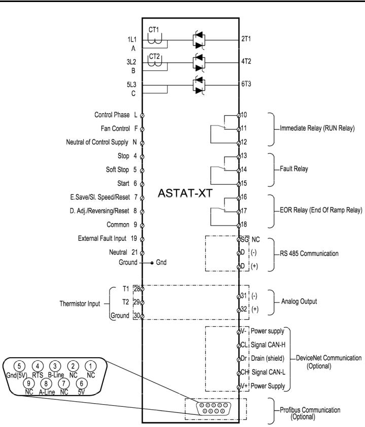
17 • Technical Specifications
3.4I/O Wiring
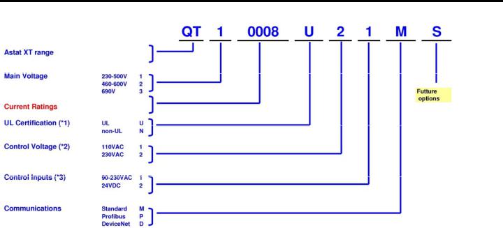
18 • Technical Specifications
3.5Ordering Information
Notes:
cUL Certification
(*1) – ASTAT-XT up to 600V, and up to 170A (Cat Numbers up to to QT10170_ or QT20170) are always cUL certified. Option “N” not available
-Units QT1 or QT2 from QTx0950_ up to QTxx1400 are not UL certified. Option “U” not available.
-Units QT3x, rated to 690V, are not UL certified. Option “U” not available
Control and Inputs Voltage
(*2) ASTAT XT standard Control Voltage configuration is option 2, Voltage 230VAC, +10%, -15% (*3) ASTAT XT standard configuration for Inputs is option 1, Voltage 90-230VAC, +10%, -15%
3.5.1Ordering Accessories
Catalog Number |
Description |
|
|
QTAKPADKIT1 |
Keypad mounting kit for ASTAT-XT up to 72A |
QTAKPADKIT2 |
Keypad mounting kit for ASTAT-XT above 72A |

19 • Technical Specifications
3.6Operating Modes
Operating Mode |
Key |
Starting Voltage |
1 |
Kick Start |
2 |
Acceleration Ramp |
3 |
|
|
|
4 |
Running mode |
5 |
Soft stop mode |
6 |
|
|
|
7 |
|
8 |
9
Starting by voltage ramp:
Starting by current limitation:
Description
5 to 80% Un. Adjustable via Starting Voltage parameter.
Fixed level of 80% Un with an adjustable time, 0-1 sec., via Kickstart Time parameter.
1-30 sec. (1-9013 sec.). Adjustable via Ramp UP Time. Secondary ramp 1-30sec. (1-9013 sec.). Adjustable via Ramp UP-2 parameter.
Ramp up modes available are:
Soft Start Curve 0 (Standard)
Soft Start Curve 1!!-3!!
Soft Start Curve 4(Torque) for linear torque control
Fast ramp (if the motor is up to speed before the end of normal ramp time) Nominal voltage
Deceleration ramp 1-30sec. (1-9013 sec.). Adjustable via Ramp DOWN Time. Secondary ramp 1-30sec. (1-9013 sec.). Adjustable via Ramp DOWN-2 parameter.
Ramp down modes available are:
Soft Stop Curve 0 (Standard)
Soft Stop Curve 1!!-3!!
Soft Stop Curve 4(Torque) for linear torque control Current limiting set point (100-500%xMotor Current)
Acceleration ramp (continuation after motor amps drop below the current limit).
Standard stopping (coast to rest)
13 Refer to section 5.5.5 page 50 for expanded setting.
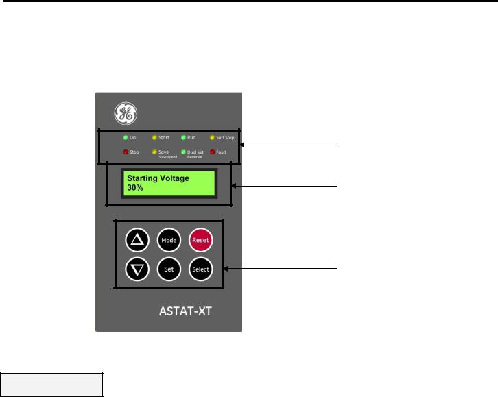
20 • Control Keypad
4.CONTROL KEYPAD
The control keypad is the interface between the ASTAT-XT and the user. The ASTAT-XT control keypad features:
Eight indication LEDs (On, Start, Run, Soft Stop, Stop, Save/Slow Speed, Dual Set/Reverse, Fault)
Two lines of 16 alphanumeric characters each with selectable languages – English, Italian, German, and Spanish. Six push-buttons - Mode, Reset, Select, Set, Up (▲) and Down (▼) keys.
(1)
(2)
(3)
ASTAT-XT control keypad
4.1LCD Arrangement
Starting Voltage 30%
Upper line displays the function.
Lower line displays the setting and\or measured values.
21 • Control Keypad
4.2Push-Buttons
Mode |
Scrolls through the display and programming menus of the ASTAT-XT.14 |
|
|
||
Select |
When a mode name is displayed, pressing this button drills down to the parameters for that mode. |
|
When a parameter is displayed, pressing this button scrolls to the next parameter. |
||
|
Allows the operator to increment adjusted values shown in the display. Operator should press this
▲button once to increment one value, or continuously to rapidly increment values up to the maximum value.
Allows the operator to decrement adjusted values shown in the display. Operator should press this
▼button once to decrement one value, or continuously to rapidly decrement values up to the minimum value.
Stores modified parameters only when you have scrolled through all parameters and Store
Set Settings Xxxxxx Parameters is displayed. After you store a parameter successfully Data Saved OK will display.15
Reset |
Resets the ASTAT-XT after a fault has been dealt with and the start command has been removed. This |
|
cancels the fault displayed and allows you to restart the motor. |
||
|
4.3Status LEDs
|
Green |
On |
Lights when the control supply voltage is connected to the ASTAT-XT. |
|
|
|
|
|
Yellow |
Start |
Lights during soft start, indicating that motor supply voltage is ramping up. |
|
|
|
Lights after completion of the starting process, indicating that motor is receiving |
|
Green |
Run |
|
|
full voltage. This LED flashes during slow speed operation. |
||
|
|
|
|
|
|
|
|
|
Yellow |
Soft Stop |
Lights during soft stop, indicating that the motor supply voltage is ramping down. |
|
|
|
|
|
Red |
Stop |
Lights when the motor is stopped. |
|
|
|
|
|
Yellow |
Save/Slow |
Lights when Energy Saving is in operation. |
|
Speed |
Flashes when the motor is running in Slow Speed. |
|
|
|
||
|
|
|
|
|
Green |
Dual |
Lights when Dual Settings is in operation. |
|
set/Reverse |
Flashes when the motor is running in Slow SP Reverse. |
|
|
|
||
|
|
|
|
|
Red |
Fault |
Lights upon operation of any of the built-in protections. |
|
|
|
|
4.4Reviewing and Modifying Parameters
Press the Mode key several times until you reach the required mode page.
Press the Select key to review parameters for this mode.
Once you reach the required parameter, use the ▼ or ▲ keys to modify its value.
To store the new parameters, press the Select key until the Store Settings Xxxxxx Parameters message displays and then press the Set key. The Data Saved OK message will display for 2 seconds.
Note:
After completing parameter settings:
•Turn control voltage OFF
•Wait 3 seconds
•Reconnect control voltage
14Pressing Mode continuously increases the speed at which the parameters change.
15Pressing the Set button at any other time has no effect.
22 • Control Keypad
•Verify that all parameters are set correctly.
4.5Special Actions Performed in Test/Maintenance Mode
4.5.1Run Self Test
Press the Mode and ▼ keys simultaneously. The LCD will display:
Test/Maintenance
Statistics
Press the Select key. The LCD will display:
Auto Test.
Press UP Key
Press the ▲ key. The LCD will display:
Self Test Passed
And after a few seconds the LCD will display:
Motor Current 0
4.5.2View Software Version
Press the Mode and ▼ keys simultaneously. The LCD will display:
Test/Maintenance
Statistics
Press the Select key twice. The LCD will display:
Firmware Version
STRT.GE-031208
Press the Mode and ▼ keys simultaneously to exit the Test/Maintenance mode. The LCD will display:
Motor Current 0
4.5.3Obtain Default Parameters
Press the Mode and ▼ keys simultaneously. The LCD will display:
Test/Maintenance
Statistics
Press the Select key three times. The LCD will display:
Store Settings
Default data
Press the Set + Mode keys simultaneously. The LCD will display:
Data Saved OK
And after a few seconds the LCD will display:
Motor Current 0
CAUTION! Obtaining Default Data erases all previously modified settings and requires the operator to reprogram all parameters that differ from the factory default.
Note: It is especially important to reprogram the Starter Current (as shown on the name plate of the ASTAT-XT), Motor Current and voltage protection values again.
4.5.4Reset Statistical Data
Press the Mode and ▼ keys simultaneously. The LCD will display:
Test/Maintenance
Statistics
Press the Select key four times. The LCD will display:
Reset Statistics
Press the Reset + Set keys simultaneously. The LCD will display:
Data Saved OK
And after a few seconds the LCD will display:
Statistical Data - **** -

23 • Control Keypad
Press the Mode and go back to:
Motor Current 0
4.5.5Calibrate Voltage and Current (Factory Use Only!)
Press the Mode and ▼ keys simultaneously. The LCD will display:
Test/Maintenance
Statistics
Press the Select key five times. The LCD will display:
Calibration VOLT
0 VOLT
Press the Select key. The LCD will display:
Calibration CURR
5% of Ir
Press the Mode and ▼ keys simultaneously to exit the Test/Maintenance mode.
4.6Mode Pages
Upon initiation of the ASTAT-XT, the LCD displays motor’s operating current:
Motor Current 0
You can review all mode pages by pressing the Mode key:
|
Main Settings |
|
|
|
- **** - |
|
|
|
Start Settings |
|
|
|
- **** - |
|
|
|
Stop Settings |
|
|
|
- **** - |
|
|
|
DUAL Settings |
|
These pages are skipped if ASTAT-XT is programmed to Minimized |
|
Parameters |
|
Mode and are shown only in Maximized Mode. Refer to section 5.5.1 |
|
Slow SP & Saving |
|
|
|
|
on page 49 for changing mode from Minimized Mode to Maximized |
|
|
Parameters |
|
Mode. |
|
Fault Settings |
|
|
|
|
|
|
|
- **** - |
|
|
|
I/O Settings |
|
|
|
Parameters |
|
|
|
COMM. Parameters |
|
|
|
- **** - |
|
|
|
Statistical Data |
|
|
|
- **** - |
|
|

24 • Control Keypad
4.7Overview of All Mode Pages and Factory Defaults
|
|
|
|
|
|
|
|
|
|
|
|
|
|
Appears only in |
|
|
|
|
|
|
|
|
|
|
|
|
|
|
|
Maximized16 |
|
|
|
|
|
|
|
|
|
|
|
|
|
|
|
|
|
|
Display Page |
|
Main Settings |
Start Settings |
Stop Settings |
DUAL Settings |
|||||||||
|
|
|
|
- **** - |
|
|
- **** - |
|
|
- **** - |
|
Parameters |
|
||
|
|
|
|
|
|
|
|
|
|
|
|
|
|
|
|
|
|
|
|
|
|
|
|
|
|
|
|
|
|
|
|
|
Function & Default |
|
Function & Default |
|
Function & Default |
|
Function & Default |
Function & Default |
|||||||
|
Motor Current |
|
|
Starter Current |
|
|
Soft Start Curve |
|
|
Soft Stop Curve |
|
Starting VOLT-2 |
|
||
|
0 |
|
|
58 AMP. |
|
|
0(Standard) |
|
|
0(Standard) |
|
30% |
|
||
|
|
|
|
|
|
|
|
|
|
||||||
|
Line Voltage |
|
|
Motor Current |
|
|
Kickstart Time |
|
|
Ramp DOWN TIME |
|
Starting CURR-2 |
|
||
|
0 Volt |
|
|
58 AMP. |
|
|
0 SEC. |
|
|
10 SEC. |
|
100% |
|
||
|
|
|
|
|
|
|
|
|
|
||||||
|
Thermistor Input. |
|
|
LINE/DELTA Conf. |
|
|
Starting Voltage |
|
|
End Torque |
|
Current Limit-2 |
|
||
|
3.1 Kohm |
|
|
Line |
|
|
|
|
30 % |
|
|
0 (MIN.) |
|
300% of Im |
|
|
|
|
|
|
|
|
|
|
|
|
|||||
|
|
|
|
Undercurrent FLT |
|
|
Starting Current |
|
|
Store Settings |
|
Ramp UP-2 |
|
||
|
|
|
|
0% of Im |
|
|
100 % |
|
|
Stop Settings |
|
10 SEC. |
|
||
|
|
|
|
|
|
|
|
|
|
|
|
||||
|
|
|
|
Undercurrent DLY |
|
|
Current Limit |
|
|
|
|
Ramp DOWN-2 |
|
||
|
|
|
|
10 SEC. |
|
|
400% OF Im |
|
|
|
|
10 SEC. |
|
||
|
|
|
|
|
|
|
|
|
|
|
|
||||
|
|
|
|
O/C JAM Fault |
|
|
Ramp UP Time |
|
|
|
|
Motor Current-2 |
|
||
|
|
|
|
850% OF Im |
|
|
10 SEC. |
|
|
|
|
31 AMP. |
|
||
|
|
|
|
|
|
|
|
|
|
|
|
||||
|
|
|
|
O/C JAM Delay |
|
|
Max. Start Time |
|
|
|
|
Store Settings |
|
||
|
|
|
|
0.5 Sec. |
|
|
30 SEC. |
|
|
|
|
Dual Settings |
|
||
|
|
|
|
|
|
|
|
|
|
|
|
|
|||
|
|
|
|
Overload Class |
|
|
Number of Starts |
|
|
|
|
|
|
||
|
|
|
|
IEC CLASS 10 |
|
|
10 |
|
|
|
|
|
|
||
|
|
|
|
|
|
|
|
|
|
|
|
|
|||
|
|
|
|
Overload Protect |
|
|
Duty Cycle Time |
|
|
|
|
|
|
||
|
|
|
|
Enabled |
|
|
30 Min. |
|
|
|
|
|
|
||
|
|
|
|
|
|
|
|
|
|
|
|
|
|||
|
|
|
|
Undervoltage FLT |
|
|
Start Lockout |
|
|
|
|
|
|
||
|
|
|
|
300 Volt |
|
|
15 Min. |
|
|
|
|
|
|
||
|
|
|
|
|
|
|
|
|
|
|
|
|
|||
|
|
|
|
Undervoltage DLY |
|
|
EOR Relay Delay. |
|
|
|
|
|
|
||
|
|
|
|
5 SEC. |
|
|
|
|
5 Sec. |
|
|
|
|
|
|
|
|
|
|
|
|
|
|
|
|
|
|
|
|||
|
|
|
|
Overvoltage FLT |
|
|
Store Settings |
|
|
|
|
|
|
||
|
|
|
|
480 Volt |
|
|
Start Settings |
|
|
|
|
|
|
||
|
|
|
|
|
|
|
|
|
|
|
|
|
|
||
|
|
|
|
Overvoltage DLY |
|
|
|
|
|
|
|
|
|
||
|
|
|
|
2 SEC. |
|
|
|
|
|
|
|
|
|
|
|
|
|
|
|
|
|
|
|
|
|
|
|
|
|
|
|
|
|
|
|
Store |
Settings |
|
|
|
|
|
|
|
|
|
|
|
|
|
|
Main |
Settings |
|
|
|
|
|
|
|
|
|
|
|
|
|
|
|
|
|
|
|
|
|
|
|
|
|
|
16 Refer to section 5.5.1 on page 49 for changing mode from Minimized Mode to Maximized Mode.

25 • Control Keypad
|
|
|
|
|
|
|
|
|
|
|
|
|
|
|
|
Only in Max. Mode16 |
|
|
Only in Max. Mode16 |
|
Only in Max. Mode16 |
|
|
|
Only in Max. Mode16 |
|
|
|
|
|
|
|
|
|
|
|
|
|
|
|
COMM. Parameters |
|
|
|
|
Slow SP & Saving |
|
|
Fault Settings |
|
|
I/O Settings |
|
|
|
|
Statistical Data |
|
|
|
Parameters |
|
|
- **** - |
|
|
Parameters |
|
|
|
- **** - |
|
- **** - |
|
|
|
|
|
|
|
|
|
|
|
|
|
|
|
|
|
Function & Default |
|
|
Function & Default |
|
Function & Default |
|
|
|
Function & Default |
|
Function & Default |
|
|
|
Energy Saving |
|
|
Phase Loss |
|
PROG. Input #7 |
|
|
|
COMM. Protocol |
|
Last Start Time |
|
|
|
0 (MIN) |
|
|
Enabled |
|
Reset |
|
|
|
Modbus |
|
No Data |
|
|
|
|
|
|
|
|
|
|
|
|
Baud Rate |
|
|
|
|
|
Slow Speed TRQ. |
|
|
Phase Sequence |
|
PROG. Input #8 |
|
|
|
|
Last Start Curr. |
|
||
|
8 |
|
|
Disabled |
|
Dual Settings |
|
|
|
9600 (MODBUS) |
|
No Data |
|
|
|
|
|
|
|
|
|
|
|
|
Parity Check |
|
|
|
|
|
Max Slow SP Time |
|
|
Auto Reset |
|
PROG. Fault Relay |
|
|
|
|
Elapsed Run Time |
|
||
|
30 SEC. |
|
|
Disabled |
|
At Fault Close |
|
|
|
EVEN |
|
0 Hours |
|
|
|
|
|
|
|
|
|
|
|
|
Station Number. |
|
|
|
|
|
Store Settings |
|
|
Thermistor Type |
|
Relay ON Delay |
|
|
|
|
Number Of Starts |
|
||
|
Slow SP & Saving |
|
|
PTC |
|
0 SEC. |
|
|
|
OFF |
|
0 |
|
|
|
|
|
|
|
|
|
|
|
|
S. Link Par. Set |
|
|
|
|
|
|
|
|
Thermistor Trip |
|
Relay OFF Delay |
|
|
|
|
Last Fault |
|
||
|
|
|
|
Disabled |
|
0 SEC. |
|
|
|
DISABLED |
|
No Data |
|
|
|
|
|
|
|
|
|
|
|
|
Ser. Link Control |
|
|
|
|
|
|
|
|
Undercurrent RST |
|
Analog Output |
|
|
|
|
Motor FLT Current |
|
||
|
|
|
|
Disabled |
|
I, 0...200% OF Im |
|
|
|
DISABLE |
|
0 % of Im |
|
|
|
|
|
|
|
|
|
|
|
|
Store Settings |
|
|
|
|
|
|
|
|
Store Settings |
|
Store Settings |
|
|
|
|
Fault Counter |
|
||
|
|
|
|
Fault Settings |
|
I/O Settings |
|
|
|
COMM. Parameters |
|
0 |
|
|
|
|
|
|
|
|
|
|
|
|
|
COMM. Protocol |
|
|
|
|
|
|
|
|
|
|
|
|
|
|
|
Previous Fault -1 |
|
|
|
|
|
|
|
|
|
|
|
|
|
Profibus |
|
No Data |
|
|
|
|
|
|
|
|
|
|
|
|
|
|
|
|
|
|
|
|
|
|
|
|
|
|
|
Baud Rate |
|
PREVIOUS Fault -9 |
|
|
|
|
|
|
|
|
|
|
|
|
|
|
||
|
|
|
|
Appears when in |
|
|
|
|
|
AUTO (Profibus) |
|
No Data |
|
|
|
|
|
|
Test/Maintenance |
|
|
|
|
|
Parity Check |
|
|
|
|
|
|
|
|
|
|
|
|
|
|
|
||||
|
|
|
|
Test/Maintenance |
|
|
|
|
|
|
|
|
||
|
|
|
|
|
|
|
|
|
AUTO (Profibus) |
|
|
|
||
|
|
|
|
***Statistics*** |
|
|
|
|
|
PROFI. Network ID |
|
|
|
|
|
|
|
|
Display and default |
|
|
|
|
|
|
|
|||
|
|
|
|
values |
|
|
|
|
OFF |
|
|
|
||
|
|
|
|
Auto Test |
|
|
|
|
S. Link Par. Set |
|
|
|
||
|
|
|
|
|
|
|
|
|
|
|
||||
|
|
|
|
Press UP Key |
|
|
|
|
Disabled |
|
|
|
||
|
|
|
|
Firmware Version |
|
|
|
|
Ser. Link Control |
|
|
|
||
|
|
|
|
|
|
|
|
|
|
|
||||
|
|
|
|
STRT-GE-270508 |
|
|
|
|
|
|
|
|||
|
|
|
|
Store Settings |
|
|
|
|
Disabled |
|
|
|
||
|
|
|
|
Default Data |
|
|
|
|
Store Settings |
|
|
|
||
|
|
|
|
|
|
|
|
|
|
|
||||
|
|
|
|
Reset Statistics |
|
|
|
|
COMM. Parameters |
|
|
|
||
|
|
|
|
|
|
|
|
|
|
COMM. Protocol |
|
|
|
|
|
|
|
|
Calibration VOLT |
|
|
|
|
|
|
|
|||
|
|
|
|
0 VOLT |
|
|
|
|
DeviceNet |
|
|
|
||
|
|
|
|
Calibration CURR |
|
|
|
|
Baud Rate |
|
|
|
||
|
|
|
|
5% of Ir |
|
|
|
|
|
|
|
|||
|
|
|
|
|
|
|
|
Set Manually |
|
|
|
|||
|
|
|
|
|
|
|
|
|
|
|
|
|
|
|
|
|
|
|
|
|
|
|
|
|
|
Parity Check |
|
|
|
|
|
|
|
|
|
|
|
|
|
|
AUTO (DeviceNet) |
|
|
|
|
|
|
|
|
|
|
|
|
|
|
DeviceNet ID |
|
|
|
|
|
|
|
|
|
|
|
|
|
|
Set Manually |
|
|
|
|
|
|
|
|
|
|
|
|
|
|
S. Link Par. Set |
|
|
|
|
|
|
|
|
|
|
|
|
|
|
Disabled |
|
|
|
|
|
|
|
|
|
|
|
|
|
|
Ser. Link Control |
|
|
|
|
|
|
|
|
|
|
|
|
|
|
Disabled |
|
|
|
|
|
|
|
|
|
|
|
|
|
|
Store Settings |
|
|
|
|
|
|
|
|
|
|
|
|
|
|
COMM. Parameters |
|
|
|
Note: There are three different groups of COMM. Protocol parameters. Each group of COMM. Protocol parameters are only valid when its corresponding optional PCB is installed.

26 • Control Keypad
4.7.1Display Mode17 – Page 018
|
Function & |
|
Unit |
|
|
Description |
|
|
Default |
|
|
|
|
|
|
|
|
|
|
|
|
|
|
|
|
|
|
|
|
|
|
|
Motor Current |
|
A |
|
|
Displays operating current of the motor. |
|
|
0 |
|
|
|
|
ASTAT-XT’s Default Display. After pressing the Mode or Select keys, a time |
|
|
|
|
|
|
|
delay is initiated. Following the delay the LCD returns to display Motor |
|
|
|
|
|
|
|
Current. |
|
|
|
|
|
|
|
If current is lower than 0.1 of the rated current of the ASTAT-XT, the display |
|
|
|
|
|
|
|
will show: I < 0.1 Ir |
|
|
|
|
|
|
|
|
|
|
Line Voltage |
|
V |
|
|
Displays the mains voltage. |
|
|
0 Volt |
|
|
|
|
|
|
|
|
|
|
|
|
|
|
|
Thermistor Input |
|
Kohm |
|
|
Displays the resistance level of the motor’s thermistor. |
|
|
3.1 Kohm |
|
|
|
|
|
|
|
|
|
|
|
|
|
|
17Displays in MINIMIZED MODE and MAXIMIZED MODE.
18Parameters cannot be programmed in page 0.

27 • Control Keypad
4.7.2Main Settings19 – Page 1
|
Function & |
|
Range |
|
Unit |
|
|
Description |
|
|
|
Default |
|
|
|
|
|
|
|
|
|
|
|
|
|
|
|
|
|
|
|
|
|
|
|
|
|
|
|
|
|
|
|
|
Starter Current |
|
8 – 1400 |
|
A |
|
|
Sets ASTAT-XT’s Rated Current (Type Unit) |
|
|
|
58 Amp. |
|
|
|
|
|
|
|
Check the name plate on the soft starter and make sure that |
|
|
|
|
|
|
|
|
|
|
digits 4 to 7 of the model name are the same as the |
|
|
|
|
|
|
|
|
|
|
Starter Current setting. For example the setting for |
|
|
|
|
|
|
|
|
|
|
model QTx0008Uxxx must be 8 Amp. Refer to section 5.1 on |
|
|
|
|
|
|
|
|
|
|
page 47. |
|
|
Motor Current |
4-175020 |
|
A |
|
|
Sets the motor’s Full load Ampere |
|
||
|
58 Amp. |
|
Based on % of |
|
|
|
|
Should be programmed as shown on the motor’s name |
|
|
|
|
|
Starter |
|
|
|
|
plate.21 |
|
|
|
|
|
Current |
|
|
|
|
Note: |
|
|
|
|
|
|
|
|
|
|
|
When setting Motor Current to a higher level than |
|
|
|
|
|
|
|
|
|
|
Starter Current, Overload Class parameter (see |
|
|
|
|
|
|
|
|
|
|
below) is automatically set to NEMA Class 10. |
|
|
LINE/DELTA Conf. |
|
Line, Inside |
|
|
|
|
Sets ASTAT-XT’s connection type.22 |
|
|
|
Line |
|
Delta |
|
|
|
|
Factory preset - features and functions not active when |
|
|
|
|
|
|
|
|
|
|
|
DELTA Conf. is configured: |
|
|
|
|
|
|
|
|
|
|
Kickstart. |
|
|
|
|
|
|
|
|
|
|
Soft Start Curve selection (Curve 0!! only) |
|
|
|
|
|
|
|
|
|
|
Slow Speed |
|
|
|
|
|
|
|
|
|
|
Phase Sequence Disabled mode |
|
|
|
|
|
|
|
|
|
|
Refer to section 8.20 on page 74 for further information. |
|
|
|
|
|
|
|
|
|
|
|
|
|
Undercurrent FLT |
|
0%=OFF; |
|
% of |
|
|
Sets Undercurrent protection. |
|
|
|
0% of Im |
20-90 |
|
|
Motor |
|
|
Trips the ASTAT-XT when the motor current drops below the |
|
|
|
|
|
|
|
|
Current |
|
|
level that was set for a time period longer than |
|
|
|
|
|
|
|
|
|
|
Undercurrent Dly. |
|
|
Undercurrent DLY |
1-40 |
|
|
sec. |
|
|
Sets the time delay for Undercurrent FLT protection. |
|
|
|
10 SEC. |
|
|
|
|
|
|
|
Note: |
|
|
|
|
|
|
|
|
|
|
Operational when the motor is running (the RUN LED is lit). |
|
|
|
|
|
|
|
|
|
|
|
|
|
O/C JAM Fault |
100-850 |
|
% of |
|
|
Sets O/C JAM Fault protection. |
|
||
|
850% of Im |
|
|
|
|
Motor |
|
|
Operational when ASTAT-XT is energized and has three trip |
|
|
|
|
|
|
|
Current |
|
|
functions: |
|
|
|
|
|
|
|
|
|
|
At all time - If I > 850% of Starter Current it trips the |
|
|
|
|
|
|
|
|
|
|
ASTAT-XT within 1 cycle (overrides the value of the O/C JAM |
|
|
|
|
|
|
|
|
|
|
Fault setting). |
|
|
O/C JAM Delay |
|
0.0 – 5 |
|
sec. |
|
|
At starting process - If I > 850% of Motor Current it trips |
|
|
|
0.5 Sec. |
|
|
|
|
|
|
|
the ASTAT-XT after O/C JAM Delay |
|
|
|
|
|
|
|
|
|
|
At run time - If I > O/C JAM Fault setting of Motor |
|
|
|
|
|
|
|
|
|
|
Current it trips the ASTAT-XT after O/C JAM Delay. |
|
|
|
|
|
|
|
|
|
|
Caution: |
|
|
|
|
|
|
|
|
|
|
The O/C JAM Fault is not intended to replace the fast |
|
|
|
|
|
|
|
|
|
|
acting fuses, required to protect the thyristors. Refer to |
|
|
|
|
|
|
|
|
|
|
section 8.18 on page 72. |
|
|
|
|
|
|
|
|
|
|
|
|
19Displays in MINIMIZED MODE and MAXIMIZED MODE.
20The lower limit can be set as low as 50% of Starter Current. The upper limit is automatically set by the ASTAT-XT and is between 100 and 126% of Starter Current.
The Motor Current can be set as high as indicated in columns “Current Rating” for Light Duty applications in the tables in section 2.1 page 8 and in section 2.2 page 9.
21When the ASTAT-XT is installed in the Inside Delta configuration set:
Motor Current = <rated motor current>/1.73.
22 When the ASTAT-XT is installed in DELTA Conf. set Motor Current = <rated motor current>/1.73.

28 • Control Keypad
|
Function & |
|
Range |
|
Unit |
|
Description |
|
|
Default |
|
|
|
|
|
|
|
|
|
|
|
|
|
|
|
|
|
|
|
|
|
|
|
|
|
|
Overload Class |
|
IEC CLASS 10; |
|
|
|
Sets Overload CLASS. |
|
|
IEC CLASS 10 |
|
IEC CLASS 20; |
|
|
|
Overload Class is operational as programmed in the |
|
|
|
|
NEMA CLASS |
|
|
|
Overload Protect parameter. (see next parameter) |
|
|
|
10; |
|
|
|
The O/L circuitry incorporates a thermal memory register |
|
|
|
|
|
NEMA CLASS |
|
|
|
that calculates heating minus dissipation of the motor. The |
|
|
|
20; |
|
|
|
ASTAT-XT trips when the register fills up. |
|
|
|
|
|
NEMA CLASS |
|
|
|
The time constant for cool down after overload trip is: |
|
|
|
30; |
|
|
|
For IEC/NEMA Class 10 – 320seconds |
|
|
|
|
|
|
|
|
|
For IEC/NEMA Class 20 – 640seconds |
|
|
|
|
|
|
|
|
For NEMA Class 30 – 960seconds |
|
|
|
|
|
|
|
|
Refer to section 2.3 on page 10 for thermal characteristic. |
|
|
|
|
|
|
|
|
Note: |
|
|
|
|
|
|
|
|
When setting Motor Current to a higher level than |
|
|
|
|
|
|
|
|
Starter Current, Overload Class parameter is |
|
|
|
|
|
|
|
|
automatically set to NEMA Class 10. |
|
|
Overload Protect |
|
Enable after |
|
|
|
Sets Overload Protection operation. |
|
|
Enabled |
|
EOR; |
|
|
|
Enable after (End Of Ramp) will set the overload |
|
|
|
|
Enabled; |
|
|
|
protection to be operative after starting process is completed |
|
|
|
|
Disabled; |
|
|
|
and (End Of Ramp) relay is energized. |
|
|
|
|
|
|
|
|
Enabled will set the overload protection to be operative at |
|
|
|
|
|
|
|
|
all time. |
|
|
|
|
|
|
|
|
Disabled will set the overload protection not to be |
|
|
|
|
|
|
|
|
operative at all time. |
|
|
|
|
|
|
|
|
ATTENTION! |
|
|
|
|
|
|
|
|
When Overload Protect is set to Disabled the motor |
|
|
|
|
|
|
|
|
is not protected for Overload!! |
|
|
Undervoltage FLT |
120-600 |
|
V |
|
Sets Undervoltage Fault level. |
|
|
|
300 Volt |
|
|
|
|
|
Trips the ASTAT-XT when mains voltage drops below the level |
|
|
|
|
|
|
|
|
that was set for a time longer than Undervoltage DLY. |
|
|
Undervoltage DLY |
|
1 –10 |
|
sec. |
|
Sets Undervoltage Fault delay23 |
|
|
5 SEC. |
|
|
|
|
|
|
|
|
|
|
|
|
|
|
|
|
|
Overvoltage FLT |
250-750 |
|
V |
|
Sets Overvoltage Fault level. |
|
|
|
480 Volt |
|
|
|
|
|
Trips the ASTAT-XT when mains voltage increases above the |
|
|
|
|
|
|
|
|
level that was set for a time longer than Overvoltage |
|
|
|
|
|
|
|
|
DLY. Can not be set lower than the Undervoltage FLT |
|
|
|
|
|
|
|
|
setting. |
|
|
Overvoltage DLY |
|
1 –10 |
|
sec. |
|
Sets Overvoltage Fault delay.24 |
|
|
2 SEC. |
|
|
|
|
|
|
|
Store Settings
Main Settings
Storing modified parameters25
To store selected parameters scroll through all parameters until you reach Store Settings Main Settings, then press the Set key.
After you store a parameter successfully the Data Saved OK message will display.
If ASTAT-XT fails to store the parameter the LCD Will display the Storage Error message (refer to section 7 on page 59 for more details).
23 Becomes operational only after the start signal.
When voltage drops to zero (voltage outage) the ASTAT-XT will trip immediately, thus overriding the delay.
24Becomes operational only after the start signal.
25Pressing the Set key when the Store Settings Xxxxx Settings message does not appear on the display has no effect.
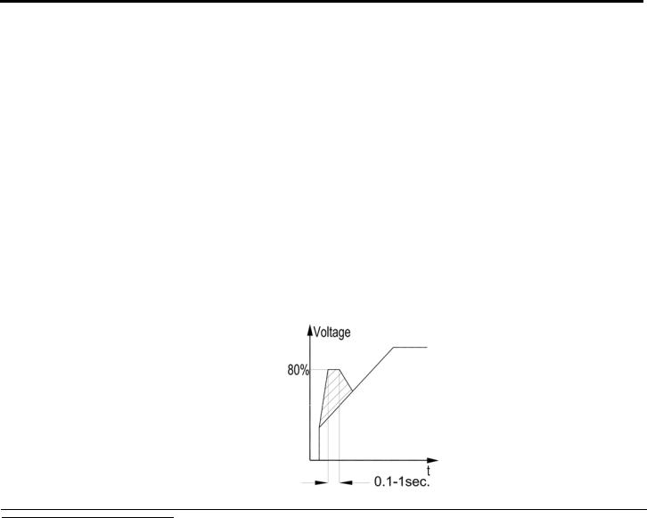
29 • Control Keypad
4.7.3 |
Start Settings26 – Page 2 |
|
|
|
|
|
||||
|
|
|
|
|
|
|
|
|
|
|
|
Function & |
|
|
Range |
Unit |
Description |
|
|||
|
|
Default |
|
|
|
|
|
|
|
|
|
|
|
|
|
|
|
|
|
||
|
Soft Start Curve |
0 |
|
|
|
|
Sets ASTAT-XT’s Soft Start Curve.27 |
|
||
|
0(Standard) |
|
(Standard) |
|
|
|
Refer to section 4.7.3.1 on page 32. |
|
||
|
|
|
1 |
!! |
|
|
|
|
|
|
|
|
|
2 |
!! |
|
|
|
|
|
|
|
|
|
3 |
!! |
|
|
|
|
|
|
|
|
|
4 |
(Torque) |
|
|
|
|
|
|
|
Kickstart Time |
|
0 –1.0 |
|
sec. |
|
Sets ASTAT-XT’s Kickstart Time.28 |
|
||
|
0 Sec. |
|
|
|
|
|
|
Kickstart level is 80% Un. |
|
|
|
|
|
|
|
|
|
|
|
Intended to start high friction loads that require high starting |
|
|
|
|
|
|
|
|
|
|
torque for a short time. |
|
|
|
|
|
|
|
|
|
|
A pulse of 80% Un without Current Limit is initiated to break the |
|
load free.
Kickstart Time is adjustable, 0.1–1sec. After this pulse the voltage is ramped down to Starting Voltage setting before ramping up again to full voltage according to the Start
Settings.
26 Displays in MINIMIZED MODE and MAXIMIZED MODE.
27 When ASTAT-XT is connected in DELTA Conf. only Soft Start Curve 0 (Standard) is applied. 28 There is no Kickstart function when ASTAT-XT is connected in DELTA Conf.
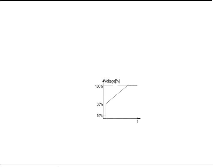
30 • Control Keypad
|
Function & |
|
Range |
|
Unit |
|
Description |
|
|
Default |
|
|
|
|
|
|
|
|
|
|
|
|
|
|
|
|
|
|
|
|
|
|
|
|
|
|
Starting Voltage |
10-50% |
|
% of |
|
Sets the motor’s Starting Voltage. |
|
|
|
30 % |
|
After |
|
mains |
|
The motor’s torque is directly proportional to the square of the |
|
|
|
|
reaching |
|
voltage |
|
voltage. |
|
|
|
|
50% the |
|
|
|
This adjustment also determines the inrush current and |
|
|
|
|
display |
|
|
|
mechanical shock. A setting that is too high may cause high |
|
|
|
|
changes to: |
|
|
|
initial mechanical shock and high inrush current. This can occur |
|
|
|
|
Starting |
|
|
|
even if Current Limit is set low because the Starting |
|
|
|
|
Current |
|
|
|
Voltage setting overrides the Current Limit setting. |
|
|
|
100-400% |
|
|
|
A setting that is too low may result in prolonged time until the |
|
|
|
|
29 |
|
|
|
motor starts to turn. In general, this setting should ensure that |
|
|
|
Starting Current |
|
|
|
|
|
the motor starts turning immediately after start signal. |
|
|
100 % |
|
|
|
|
|
|
|
Note:
When Starting Voltage is set its maximum value, this displays changes to Starting Current.
When Starting Current is set the ASTAT-XT causes current ramp instead of voltage ramp.
29The range of the Starting Voltage can be extended to 5-80% by using the EXPANDED SETTING as described in section 5.5.5 page 50.
Loading...