


 Loading...


 TM
TM
This book is referred to SW version 9.2X00.
This book replaces the Instruction Book GEH-6129 Rev. 7.1
These instructions do not purport to cover all details or variations in equipment, nor to provide every possible contingency to be met during installation, operation, and maintenance. If further information is desired or if particular problems arise that are not covered sufficiently for the purchaser’s purpose, the matter should be referred to GE Consumer & Industrial.
This document contains proprietary information of General Electric Company, USA and is furnished to its customer solely to assist that customer in the installation, testing, operation, and/or maintenance of the equipment described. This document shall not be reproduced in whole or in part nor shall its contents be disclosed to any third party without the written approval of GE Consumer & Industrial..
© 2008 by General Electric Company, USA. All rights reserved.
|
Table of Contents |
|
1. PRECAUTIONS AND WARNINGS ........................................................................................ |
5 |
|
2. PREFACE ............................................................................................................................... |
7 |
|
2a. |
Important Introduction .................................................................................................................................... |
7 |
2b. |
Drive Memory ................................................................................................................................................ |
7 |
2c. Basic control wiring and starting .................................................................................................................... |
7 |
|
2d. |
GE Control System toolbox VS keypad setup ............................................................................................... |
8 |
3. PRE POWER CHECKS .......................................................................................................... |
9 |
|
3a. Grounds/grounding ........................................................................................................................................ |
9 |
|
Regulator board terminals ................................................................................................................................... |
9 |
|
3b. |
Meggering ...................................................................................................................................................... |
9 |
3c. Connections ................................................................................................................................................... |
9 |
|
3d. motor data tabulation ................................................................................................................................... |
10 |
|
Nameplate dual speed rating ............................................................................................................................. |
10 |
|
3e. field current calibration dipswitch S14 .......................................................................................................... |
11 |
|
3f. Regulation card jumper settings ................................................................................................................... |
13 |
|
4. POWER UP CHECKS AND INITIAL CONFIGURING ......................................................... |
14 |
|
4a. |
Don’t turn on power yet.....check power input ............................................................................................. |
14 |
4b. |
Power up ..................................................................................................................................................... |
14 |
4c. Loading default settings ............................................................................................................................... |
14 |
|
5. INITIAL PARAMETER SETUP ............................................................................................. |
15 |
|
6. CURRENT REGULATOR SELF TUNE ................................................................................ |
18 |
|
7. CHECK MOTOR/ROLL ROTATION, SPEED FEEDBACK POLARITY, AND |
|
|
CALIBRATIONS ................................................................................................................... |
19 |
|
7a. |
Check motor/roll rotation .............................................................................................................................. |
19 |
7b. |
Calibrations .................................................................................................................................................. |
19 |
7c. Checking current regulator performance using parameter Eint ................................................................... |
19 |
|
8. SETUP SPEED FEEDBACK ................................................................................................ |
20 |
|
8a. |
Check speed feedback polarity ................................................................................................................... |
20 |
8b. |
Setup ENC 2 for digital encoder for speed feedback ................................................................................. |
20 |
8c. ENC 1 for digital encoder for speed feedback ............................................................................................. |
21 |
|
8d. Analog tachometer ....................................................................................................................................... |
21 |
|
8e. |
Save setup ................................................................................................................................................... |
22 |
9.CONFIGURE ADDITIONAL MOTOR FIELD PARAMETERS............................................... |
23 |
|
9a. Configure field weakening operation ........................................................................................................... |
23 |
9b. hints on Flux regulator stability .................................................................................................................... |
23 |
10. SPEED SELF TUNE ........................................................................................................... |
24 |
11. SAVE PARAMETERS TO RETAIN IN PERMANENT MEMORY ....................................... |
24 |
12. OTHER COMMON SETUP PARAMETERS ....................................................................... |
25 |
12a. Terminal board input control VS keypad .................................................................................................... |
25 |
12b. Configurable I/O ......................................................................................................................................... |
25 |
12c. Configure jog operation.............................................................................................................................. |
26 |
13. INTERNAL REPLACEMENT FUSES................................................................................. |
27 |
14. BASIC OPERATING DESCRIPTIONS ............................................................................... |
28 |
14 a. standard inputs functional description ...................................................................................................... |
28 |
14b. Regulation card LEDs ................................................................................................................................ |
28 |
14c. Keypad programmer LED description ........................................................................................................ |
28 |
14 d. Keypad menu structure............................................................................................................................. |
29 |
15. QUICK TROUBLESHOOTING ........................................................................................... |
30 |
15a. Regulation card testpoints ......................................................................................................................... |
30 |
15b. Failure messages and troubleshooting hints ............................................................................................. |
30 |
DV-300 Adjustable Speed Drives
1. PRECAUTIONS AND
WARNINGS
According to the EEC standards the DV300 and accessories must be used only after checking that the machine has been produced using those safety devices required by the 89/392/EEC set of rules, as far as the machine industry is concerned.
Drive systems cause mechanical motion. It is the responsibility of the user to insure that any such motion does not result in an unsafe condition. Factory provided interlocks and operating limits should not be bypassed or modified.
WARNING - ELECTRICAL SHOCK AND BURN HAZARD:
When using instruments such as oscilloscopes to work on live equipment, the oscilloscope’s chassis should be grounded and a differential amplifier input should be used. Care should be used in the selection of probes and leads and in the adjustment of the oscilloscope so that accurate readings may be made. See instrument manufacturer’s instruction book for proper operation and adjustments to the instrument.
WARNING - FIRE AND EXPLOSION HAZARD:
Fires or explosions might result from mounting drives in hazardous areas such as locations where flammable or combustible vapors or dusts are present. Drives should be installed away from hazardous areas, even if used with motors suitable for use in these locations.
WARNING - STRAIN HAZARD:
Improper lifting practices can cause serious or fatal injury. Lift only with adequate equipment and trained personnel.
WARNING:
Replace all covers before applying power to the drive. Failure to do so may result in death or serious injury.
WARNING:
Adjustable speed drives are electrical apparatus for use in industrial installations. Parts of the drives are energized during operation. The electrical installation and the opening of the device should therefore only be carried out by qualified personnel.
Improper installation of motors or drives may therefore cause the failure of the device as well as serious injury to persons or material damage.
Follow the instructions given in this manual and observe the local and national safety regulations applicable.
CAUTION:
Do not connect power supply voltage that exceeds the standard specification voltage fluctuation permissible. If excessive voltage is applied to the Drive, damage to the internal components will result.
CAUTION:
Do not operate the drive without the ground wire connected. The motor chassis should be grounded to earth through a ground lead separate from all other equipment ground leads to prevent noise coupling.
The grounding connector shall be sized in accordance with the NEC or Canadian Electrical Code. The connection shall be made by a UL listed or CSA certified closed-loop terminal connector sized for the wire gauge involved. The connector is to be fixed using the crimp tool specified by the connector manufacturer.
CAUTION:
Do not perform a megger test between the Drive terminals or on the control circuit terminals.
CAUTION:
Because the ambient temperature greatly affects drive life and reliability, do not install the drive in any location that exceeds the allowable temperature. Leave the ventilation cover attached for temperatures of 40° C (104° F) or below.
CAUTION:
If the drive’s Fault Alarm is activated, consult the TROUBLESHOOTING section of the instruction book, and after correcting the problem, resume operation. It is not recommended to reset the alarm automatically by external sequence, etc.
—————— Quick Start up guide —————— |
5 |
QS |
|
GEH-6129 |
|
|
CAUTION: |
|
8. The electrical commissioning should only |
|
Be sure to remove the desicant dryer packet(s) when |
|
be carried out by qualified personnel, who |
|
|
are also responsible for the provision of a |
||
unpacking the Drive. (If not removed these packets may |
|
||
|
suitable ground connection and a cable |
||
become lodged in the fan or air passages and cause the |
|
||
|
protection for the power supply in accordance |
||
Drive to overheat). |
|
||
|
with the local and national regulations. The |
||
|
|
|
|
CAUTION: |
|
motor must be protected against overloads. |
|
|
9. No dielectric tests using meggers or hi pots |
||
The Drive must be mounted on a wall that is constructed |
|
||
|
should be carried out on the drive. A suitable |
||
of heat resistant material. While the drive is operating, |
|
measuring instrument (internal resistance of |
|
the temperature of the Drive’s cooling fins can rise to a |
|
at least 10 kΩ/V) should be used for |
|
temperature of 90° C (194°F). |
|
measuring the signal voltages. |
|
NOTE! |
The terms “converter”, “controller” and |
|
10.It is recommended to disconnect the drive |
|
from the AC input feeder to prevent |
||
|
“drive” are sometimes used interchangably |
|
unintentional running in the event of a failure, |
|
throughout the industry. We will use the term |
|
even if the drive is disabled. |
|
“drive” in this document |
|
|
NOTE! |
1. Never open the device or covers while the |
NOTE! |
The DV-300 operates from the inputs: start |
|
AC input power supply is switched on. |
||
|
|
and enable. If the enable input / signal is |
|
|
Minimum time to wait before working on the |
|
|
|
|
removed, the start signal is not automatically |
|
|
terminals or inside the device is listed in the |
|
|
|
|
removed. Re establishing the enable signal |
|
|
instruction book |
|
|
|
|
with the start signal already present can cause |
|
|
2. Do not touch or damage any components |
|
|
|
|
motor rotation. |
|
|
when handling the device. The changing of |
|
|
|
the isolation gaps or the removing of the |
|
This guide highlights simplified steps to |
|
isolation and covers is not permissible. If the |
|
|
|
|
program and troubleshoot the DV-300 drive. |
|
|
front plate has to be removed because of a |
|
|
|
room temperature higher than 40 degrees, the |
|
|
|
user has to ensure that no accidental contact |
|
In is intended to be used as a aid for trained |
|
with live parts may occur. |
|
personnel, and to complement the DV-300 |
|
3. Protect the device from extreme |
|
Instruction Book, after the drive is installed |
|
environmental conditions (temperature, |
|
in accordance with the DV-300 Instruction |
|
humidity, shock etc.) |
|
Book. |
4.No external voltage should be connected to the output of the converter (terminals C & D).
5.When engaging a running motor, the Auto capture function (Auto capture in the ADD SPEED FUNCT menu) must be activated.
6.Only an standard inductive DC motor load should be connected to the output of the drive (terminals C & D).
7.Always connect the Drive to the protective ground (PE) via the marked connection terminals (PE2) and the housing (PE1). The discharge current to earth may be greater than 3.5 mA. A fixed (non disconnectable) ground connection must be provided for this, to comply with EN 50178 (VDE 0160). It is aso recommended that the ground cable should have a cross section of at least 10 mm2.
QS |
6 |
—————— Quick Start up guide —————— |
DV-300 Adjustable Speed Drives
2. PREFACE
2a. Important Introduction
This startup guide is based on starting up the DV-300 out of the box from the factory, based on factory default settings.
This guide will walk the user through sequential steps and checkpoints for startup. It is recommended to follow this guide sequentially without skipping steps unless this guide instructs the user to do so.
Parameter menus and names will be shown in a keypad screen symbol, for example:
SPEC FUNCTIONS
Save parameters
parameter names will also be shown in brackets [save parameters]
2b. Drive Memory
There are two memories for drive parameters. One is the active memory which is always the one currently in use by the drive. The other is the permanent memory which is the drive accesses on power up. This is the ONLY time when the drive looks at permanent memory. All file uploads and downloads, all changes, etc. are made only to the active memory and read from the active memory. The only time permanent memory is used in any way is that when it is booted into active memory on power up, and when it is stored using the “Save Parameters” command.
When parameters are changed during set up, the changes are not permanent. The parameters changes are temporarily used, but unless [SAVE PARAMETERS] is executed, after recycling power, the changes are lost. This is an advantage to “experiment” with a parameter change to see how the change works, and not modify the permanent set-up.
As parameters are entered it is recommended to occasionally save entered data. The [SAVE PARAMETER]command is located at the end of the START UP, TUNING, and under the SPEC FUNCTIONS menu.
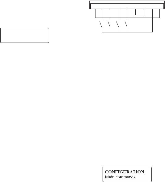
2c. Basic control wiring and starting
The terminal board inputs provide the user a hardwired control means to sequence the drive.
For testing, the inputs can be wired using a local switch box per the drawing below.
The actual control interface can be used if it has been checked out, and is a convenient and reliable control means.
11 1 2 1 3 1 4 1 5 1 6 1 8 1 9 2 0
11 - power supply common
12 - enable (close to activate)
13 - start (close to activate)
14 - fast stop (open to activate)
15 - external fault (open to activate)
16 - common for TB pts 11 -15
18 - + 24 V common
19 - + 24 VDC
20 - ground
After the control circuits are wired, and proven to operate, repower the DV-300.
Close only the switch for EXTERNAL FAULT input. Reset external drive fault with the keypad’s CANC key.
The default DV-300 configuration sets the control inputs in a “digital” mode, which is for keypad and PC control. In this mode, the terminal board inputs must be connected to 24 VDC as well as commanded from the keypad or PC.
This mode is set by parameter:
When this parameter is set to terminals, the terminal board inputs control the drive.
When this parameter is set to digital, the keypad, PC, or bus controls the sequencing, but opening the terminal board input will also cause the signal to drop out.
—————— Quick Start up guide —————— |
7 |
QS |
GEH-6129
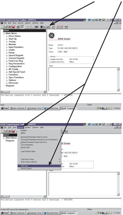
2d. GE Control System toolbox VS keypad setup
After following the suggestions for startup using Hints, pre power checks , and power up checks, a user configuring the drive with the GE Control System toolbox can follow the wizards and self tune menus to complete the setup.
QS |
8 |
—————— Quick Start up guide —————— |

DV-300 Adjustable Speed Drives
3. PRE POWER CHECKS
3a. Grounds/grounding
Verify an AC power ground wire exists from the incoming power / isolation transformer to the DV-300 input ground terminal.
Verify the ground lead of the DV-300 output terminal is wired to the motor, or the motor is properly grounded.The DV-300 power supply, terminal point 11, may be referenced to ground through a different ground circuit, or may be wired to the same ground by connecting terminal point 11 to terminal point 10 or 20.
Verify theAC input leads, DC output armature and field leads, and control wiring to and from the drive terminals are not grounded.
Use a digital voltmeter or equivalent to take these readings if the wiring is attached to the drive. Remember that the 0V terminal may be intentionally grounded.
Isolated field wiring generally reads at least 2-3 MW to ground.
3b. Meggering
Cabling must be disconnected or isolated from the DV300 drive when meggered or hi potted. Drive damage could result if this advice is not followed.
3c. Connections
Without applying power, double check all connections and wire terminals to make sure they are tight.
Verify each connection is wired per wiring diagrams, and are appropriate for the current and voltage levels specified.
Regulator board terminals
1,2 |
= programmable analog input 1, |
17 |
= no connection, |
3,4 = programmable analog input 2, |
18 = common for the 24V power supply, |
||
5,6 = programmable analog input 3 |
19 |
= + 24 VDC output, 20 = ground |
|
7 = + 10 V , 8 = -10V, 9 = +/- 10 V supply common , |
XE1 ( ENC1) 9 pin sinusoidal encoder input |
||
10 = ground, |
XE2 ( ENC2) 9 pin incremental encoder input |
||
11 = common |
DC tach input: - , + terminals for DC tach. max volts ≤ 108 no jumper, |
||
12 |
= enable input, 13 = start input, |
|
108 ≤ max volts ≤ 188 VDC jumper B & C |
14 |
= fast stop input, 15 = external fault input, |
|
188 ≤ max volts ≤ 340 VDC jumper A & C |
16 |
= common point for terminals 12 through 15, |
20 |
= Screen connection (PE) (connected w/housing) |
—————— Quick Start up guide —————— |
9 |
QS |

GEH-6129
3d. motor data tabulation
Before commissioning, it is recommended to record the actual motor nameplate data. Also record gearbox, and attached roll diameter, or any appropriate mechanical data that may be needed during setup.
This table may be used as a guide to record motor nameplate and application data
|
Typical DC Motor Nameplate |
|
HP (kW) |
RPM |
Volts |
Arm Amps |
|
|
Fld Amps |
Fld ohms 25 C |
|
Fld is an abbreviation for field
Gear in speed : |
|
rpm |
· gear in speed is the top motor rpm to achieve rated machine speed
Acceleration time : |
|
seconds |
|
|
|||||
Deceleration time : |
|
seconds |
|
|
|||||
Field control : constant current, (fixed field current) |
|
|
|||||||
(circle one) |
field weakening (see example below) |
|
|
||||||
tachometer type : analog |
|
|
V / |
|
RPM see jumpers in 3.f. |
||||
and calibration digital tacho into Encoder 2 |
|
PPR see jumpers in 3.f. |
|||||||
|
|
|
|
|
|||||
(circle one) |
None see jumpers note in 3.f. |
|
|
||||||
Nameplate dual speed rating
The value for RPM may be represented with two values, the first representing base speed , which is the rpm at nameplate volts and nameplate field current.
A second RPM value, if shown, corresponds to rated top speed, which is achieved at rated nameplate volts, and a weak field setting. The weak field setting would correspond to the second value of field amps.
For the nameplate below, base speed is 1750 rpm @ 3 amps field and top speed is 2300 rpm @ 1 amp field
|
Typical DC Motor Nameplate |
|
|
HP (kW) |
20 |
RPM 1750 / 2300 |
Volts 500 |
Arm Amps |
32 |
|
|
Fld Amps |
3.0 / 1.0 |
Fld ohms 25 C |
72 |
Verify the motor data matches the drive power rating, output voltages, and required motor speed is achievable.
If files in the GE Control System Toolbox were predefined off-line, verify the entered data is correct before downloading to the drive
QS |
10 |
—————— Quick Start up guide —————— |
Loading...