


*DJJHQDX
Installation instructions2
Notice de montage12
Instrucciones de instalación22
BO 450/451 612 BO 480/481 613
Oven
Four
Horno

en-us
Table of Contents
9 Safety Definitions |
2 |
|
|
IMPORTANT SAFETY INSTRUCTIONS |
3 |
Appliance Handling Safety |
3 |
Safety Codes and Standards |
3 |
Electric Safety |
3 |
Related Equipment Safety |
4 |
Proposition 65 Warning |
4 |
Transport |
4 |
|
|
Before you begin |
5 |
Tools and parts needed |
5 |
Parts included |
5 |
Power Requirements |
5 |
Planning notes |
5 |
|
|
Preparing Kitchen Units |
5 |
|
|
Dimensions and Cabinet Requirements |
6 |
General Cabinet Requirements |
6 |
Dimensions for 24" Wall-Mounted Units |
6 |
Dimensions for 30" Wall-Mounted Units |
7 |
|
|
Removing Packaging |
8 |
|
|
Install Appliance |
8 |
Mount to Cabinet |
8 |
Adjusting the door |
9 |
Connect Electrical Supply |
10 |
Connection to the home network (LAN) |
10 |
Combination with combi-steam oven |
10 |
Combination with warming drawer, width 24" (60 cm) |
10 |
Combination with warming drawer, width 30" (76 cm) |
10 |
Check the Installation |
10 |
Removal |
10 |
|
|
Customer service |
11 |
9 Safety Definitions
9 WARNING
This indicates that death or serious injuries may occur as a result of non-observance of this warning.
9 CAUTION
This indicates that minor or moderate injuries may occur as a result of non-observance of this warning.
NOTICE
This indicates that damage to the appliance or property may occur as a result of non-compliance with this advisory.
Note: This alerts you to important information and/or tips.
2

9 IMPORTANT SAFETY INSTRUCTIONS
READ AND SAVE THESE INSTRUCTIONS
9WARNING
If the information in this manual is not followed exactly, fire or shock may result causing property damage or personal injury.
CAN/CSA C22.2 No. 150 - Microwave Ovens
UL 923 - Microwave Cooking Appliances
CSA C22.2 No. 64 - Household Cooking and Liquid-Heating Appliances
9WARNING
Do not repair, replace or remove any part of the appliance unless specifically recommended in the manuals. Improper installation, service or maintenance can cause injury or property damage. Refer to this manual for guidance. All other servicing should be done by an authorized servicer.
Appliance Handling Safety
Unit is heavy and requires at least two people or proper equipment to move.
Do not lift appliance by door handle.
Hidden surfaces may have sharp edges. Use caution when reaching behind or under appliance.
Safety Codes and Standards
This appliance complies with the latest version of one or more of the following standards:
CAN/CSA C22.2 No. 61 - Household Cooking Ranges
UL 858 - Household Electric Ranges
UL 1026 - Electric Household Cooking and Food Serving Appliances
It is the responsibility of the owner and the installer to determine if additional requirements and/or standards apply to specific installations.
Electric Safety
Before you plug in an electrical cord, be sure all controls are in the OFF position.
If required by the National Electrical Code (or Canadian Electrical Code), this appliance must be installed on a separate branch circuit.
Installer - show the owner the location of the circuit breaker or fuse. Mark it for easy reference.
Important - save these instructions for the local electrical inspector’s use.
Before installing, turn power OFF at the service panel. Lock service panel to prevent power from being turned ON accidentally.
Refer to data plate for more information. See “Data Plate” under “Service” for data plate location.
Be sure your appliance is properly installed and grounded by a qualified technician. Installation, electrical
3
9 IMPORTANT SAFETY INSTRUCTIONS
READ AND SAVE THESE INSTRUCTIONS
connections and grounding must comply with all applicable codes.
Related Equipment Safety
Remove all tape and packaging before using the appliance. Destroy the packaging after unpacking the appliance. Never allow children to play with packaging material
Never modify or alter the construction of the appliance. For example, do not remove leveling legs, panels, wire covers or anti-tip brackets/screws.
Before starting up the appliance, remove any packaging material and adhesive film from the cooking compartment and the door.
Proposition 65 Warning:
This product may contain a chemical known to the State of California, which can cause cancer or reproductive harm. Therefore, the packaging of your product may bear the following label as required by California:
67$7( 2) &$/,)251,$ 352326,7,21 :$51,1*
:$51,1*
&DQFHU DQG 5HSURGXFWLYH +DUP ZZZ3 :DUQLQJV FD JRY
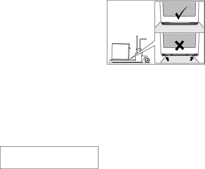
Transport
To avoid damage to the oven vent, use the transport method shown in the picture below.
4

Before you begin
Tools and parts needed
Philips head screwdriver
1/8" drill bit and drill
Measuring tape
Parts included
Built-in oven
3 Torx screws
Power Requirements
The outlet must be properly grounded in accordance with all applicable codes.
Planning notes
Door hinge not interchangeable.
Distance from furniture body to door front 1.85” (47 mm).
Distance from furniture body to outer edge of door handle 3.7” (94 mm) after retrofitting the handle (special accessory).
Pay attention to the front protrusion, possibly including the door handle, for opening drawers at the sides.
When planning a corner solution, pay attention to the door opening angle of at least 90°.
Before you begin en-us
Preparing Kitchen Units
Kitchen units must be temperature-resistant up to 195° F (90 °C) and adjoining furniture frontages up to 160° F (70 °C).
Ventilation cut-out in the built-in cupboard's intermediate shelf: at least 0.8 in to 1.65 ft (20 x 500 mm).
The wall socket must be outside the built-in niche.
Cut recesses on the furniture before inserting the appliance. Remove any shavings, as these can affect the operation of electrical components.
Secure unsecured furniture items to the wall using a commercially available bracket.
Only install the appliance so high that accessories can be removed with ease.
5
en-us Preparing Kitchen Units
Dimensions and Cabinet Requirements
General Cabinet Requirements
Cabinet requirements vary depending on the model to be installed. Please consult the section “Dimensions” for the details pertaining to your particular model.
All models require:
¼" (6.4 mm) space between the side of the appliance and an adjacent wall or cabinet door when installed at the end of a cabinet run.
The cabinet base must be flat and capable of supporting the weight of your appliance when in use. See the appropriate weight for your model in the “Dimensions” section pertaining to your particular model.
Dimensions for 24" Wall-Mounted Units
BO 450/451-612
Appliance Dimensions


|
|
PP
Cabinet Dimensions
PLQ
ZLWK DYHF FRQ %$PLQ
/$1
|
|
|
|
|
|
PLQ |
|
|
|
|
|
|
|
|
|||
|
|
|
|||
|
|
PLQ |
|
||
|
|
|
|||
|
|
|
|
||
|
|
|
|
|
|
|
|
|
|
|
|
PLQ
NOTICE
The cabinet base must be flat and capable of supporting a weight of at least 142 lbs (64.1 kg).
6
Preparing Kitchen Units en-us
Dimensions for 30" Wall-Mounted Units |
Cabinet Dimensions |
||
BO 480/481-613 |
|
PLQ |
|
ZLWK DYHF FRQ %$PLQ |
|||
|
|||
Appliance Dimensions |
/$1 |
|
|
|
|||
|
|||
|
|
|
|
|
|
|
|
|
|
|
|
|
|
|
|
|
|
|
||
|
|
|
|
|
|
|
PLQ |
|
|
|
|
|
|
|
|
|
|
|||
|
|
|
PLQ |
|
||
|
|
|
||||
|
|
|
||||
|
|
|
|
|||
|
|
|
|
|
||
|
|
|
|
|
|
|

PLQ

|
|
PP
NOTICE
The cabinet base must be flat and capable of supporting a weight of at least 169.5 lbs (76.9 kg).
|
PP |
|
7

en-us Preparing Kitchen Units
Removing Packaging
NOTICE
To prevent damage to your floor keep the unit in its packaging base until ready to be placed in the cabinet opening. Do not slide the unit across the flooring.
Different models use different packaging materials. Actual brackets may look differently. Bracket remains in packaging base.
1.Cut straps on outside of box.
2.Remove cardboard box.
3.Remove all top and side cardboard and Styrofoam braces.
4.Place oven in front of cabinets where it is to be installed.
Install Appliance
Note: The appliance is heavy. It is advisable to install it with a second person.
NOTICE
Before installing the appliance, be sure to verify the cabinet dimensions and electrical connections.
Mount to Cabinet
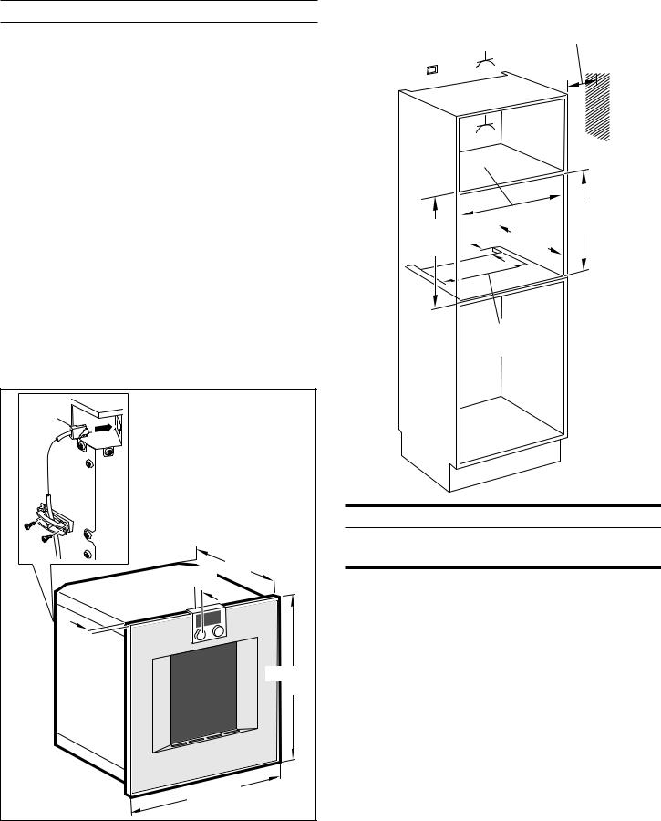
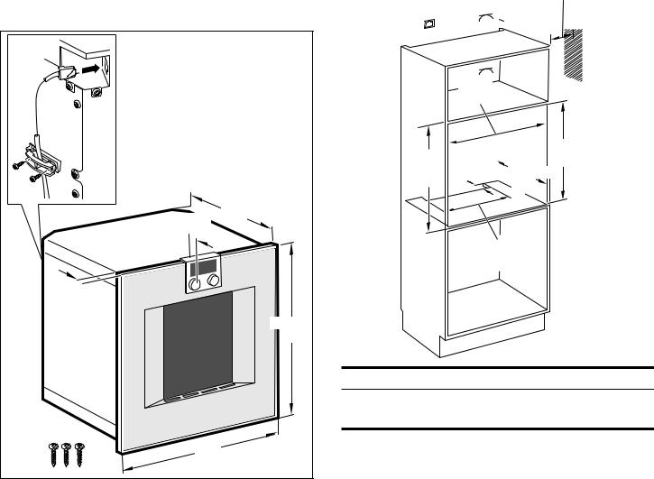
If there is no fitted shelf above the appliance, secure the appliance against tipping over when the door is opened. Fit two standard angles 3/16” (5 mm) above the appliance at 17 3/4” (450 mm) depth inside the cabinet.
1.Do not kink or trap the connecting cable, or route it over sharp edges.
2.Centre the appliance.
There must be an air gap of 3/16” (5 mm) between the appliance and adjacent cabinets.
3.Using a spirit level, adjust the appliance so that it is perfectly level.
8

4.Screw the appliance into place. Remove the transportation lock from the door.
|
|
Adjusting the door
For precise alignment, the appliance door can be slightly adjusted.
For this purpose, slightly pull out the appliance from the built-in cut-out. At the top of the appliance there is an oval opening located on the hinge side. Slightly loosen both screws (Inbus 5 mm), but do not remove them!
Preparing Kitchen Units en-us
|
Align the door via the lateral screw (Torx 20).
7RU[ |
|
Tighten both screws (Inbus 5 mm) again.
|
Notes |
The alignment of the appliance door can be adjusted via the upper hinge, in order to achieve a precise gap size of the top edge of the door to the upper air output.
The height of the door cannot be adjusted.
The device door is already aligned when the appliance is delivered. You do not normally need to align the door.
9
en-us Preparing Kitchen Units
Connect Electrical Supply
Three wire connection
BO 450/451-612
1.Connect red wire from oven to red electrical supply wire (hot wire).
2.Connect black wire from oven to black electrical supply wire (hot wire).
3.Connect yellow/green ground oven wire to bare ground electrical supply wire.
Attach flexible conduit to the junction box.
To facilitate serviceability, the flex conduit must not be shortened and should be routed to allow for temporary removal of the oven.
Four wire connection
BO 480/481-613
1.Connect red wire from oven to red electrical supply wire (hot wire).
2.Connect black wire from oven to black electrical supply wire (hot wire).
3.Connect white wire from oven to white electrical supply wire (neutral).
4.Connect yellow/green ground oven wire to electrical supply ground wire.
Attach flexible conduit to the junction box.
To facilitate serviceability, the flex conduit must not be shortened and should be routed to allow for temporary removal of the oven.
Connection to the home network (LAN)
This appliance is network-compatible and can be connected to the home network using a LAN cable (LAN cable not included). Before installation, plug the LAN cable into the socket on the rear of the appliance and secure it using the strain relief. Connect the LAN cable to a network socket.
Combination with combi-steam oven
Fit the combi-steam oven first. Pay attention to the combisteam oven's installation instructions.
For an installation depth of 550 mm (approx. 1.8 ft), position the water hoses and the connecting cable in the area of the housing cut-out.
Combination with warming drawer, width 24" (60 cm)
Fit the warming drawer first. Pay attention to the warming drawer's installation instructions.
Slide the oven onto the warming drawer and into the builtin cabinet. When sliding it in, do not damage the warming drawer's panel.
Combination with warming drawer, width 30" (76 cm)
Installation BO/BS (width 30" (76 cm)) over warming drawer WS only with dimensionally stable partition floor.
Check the Installation
9 WARNING
Before you plug in an electrical cord or turn on power supply, make sure all controls are in the OFF position.
Switch on the circuit breaker.
Verify that elements function properly.
Removal
1.Disconnect the appliance from the power supply.
2.Undo the fastening screws.
3.Raise the appliance slightly and pull it out completely.
10
 Loading...