


 Loading...
Gaggenau |
|
Installation instructions .......................... |
2 |
Notice de montage ............................... |
21 |
Instrucciones de instalación ................ |
40 |
AI 442 720 AI 442 760
Hood
Hotte aspirante
Campana extractora
Safety Definitions
9WARNING
This indicates that death or serious injuries may occur as a result of non-observance of this warning.
9CAUTION
This indicates that minor or moderate injuries may occur as a result of non-observance of this warning.
NOTICE: This indicates that damage to the appliance or property may occur as a result of non-compliance with this advisory.
Note: This alerts you to important information and/or tips.
2
9 IMPORTANT SAFETY INSTRUCTIONS
READ AND SAVE THESE INSTRUCTIONS
INSTALLER: LEAVE THESE INSTRUCTIONS WITH THE APPLIANCE AFTER INSTALLATION IS COMPLETE.
IMPORTANT: SAVE THESE INSTRUCTIONS FOR THE LOCAL ELECTRICAL INSPECTOR'S USE.
WARNING
If the information in this manual is not followed exactly, fire or shock may result causing property damage or personal injury.
WARNING
Do not repair, replace or remove any part of the appliance unless specifically recommended in the manuals. Improper installation, service or maintenance can cause injury or property damage. Refer to this manual for guidance. All other servicing should be done by an authorized servicer.
WARNING
WARNING – TO REDUCE THE RISK OF FIRE, ELECTRIC SHOCK, OR INJURY TO PERSONS, OBSERVE THE FOLLOWING:
‒Installation work and electrical wiring must be done by qualified person(s) in accordance with all applicable codes and standards, including firerated construction.
‒Sufficient air is needed for proper combustion and exhausting of gases through the flue (chimney) of fuel burning equipment to prevent back drafting. Follow the heating equipment manufacturer’s guideline and safety standards such as those published by the National Fire Protection Association (NFPA), and the American Society for Heating, Refrigeration and Air Conditioning Engineers (ASHRAE), and the local code authorities.
‒When cutting or drilling into wall or ceiling, do not damage electrical wiring and other hidden utilities.
‒Ducted fans must always be vented to the outdoors.
WARNING
The applicable regulations of the energy supply companies and the regional construction regulations must be observed when installing the hood.
WARNING
Risk of fire
Grease deposits in the grease filter can catch fire. Never work with a naked flame near the appliance (e.g. flambéing). Install the unit near a heat-producing appliance for solid fuels (e.g. wood or coal) only if there is a closed, non-detachable cover. There must be no flying sparks.
WARNING
Risk of fire
Operating several gas burners at the same time gives rise to a great deal of heat. The ventilation appliance may become damaged or catch fire. The ventilation appliance must only be combined with gas burners that do not exceed the maximum total output of 61,000 BTU/ hr (18 kW). If 41,000 BTU/hr (12 kW) is exceeded, the local regulations concerning room ventilation, room size, and combination with ventilation devices in exhaust and recirculating operation must be followed.
WARNING
To reduce risk of fire and to properly exhaust air, be sure to duct air outside. Do not vent exhaust air into spaces within walls, ceilings, attics, crawl spaces or garages.
WARNING
To reduce the risk of fire, use only metal ductwork.
3
9 IMPORTANT SAFETY INSTRUCTIONS
READ AND SAVE THESE INSTRUCTIONS
WARNING
When the hood is operated in exhaust-air mode simultaneously with a different burner which also makes use of the same chimney (such as gas, oil or coal-fired heaters, continuous-flow heaters, hot-water boilers) care must be taken to ensure that there is an adequate supply of fresh air which will be needed by the burner for combustion.
Safe operation is possible provided that the under pressure in the room where the burner is installed does not exceed 4 Pa (0.04 mbar).
This can be achieved if combustion air can flow through non-lockable openings, e.g. in doors, windows and via the air-intake/exhaust-air wall box or by other technical measures, such as reciprocal interlocking, etc.
WARNING
Avoid carbon monoxide poisoning – Provide adequate air intake so combustion gases are not drawn back into the room.
An air-intake/exhaust-air wall box by itself is no guarantee that the limiting value will not be exceeded.
Note: When assessing the overall requirement, the combined ventilation system for the entire household must be taken into consideration. This rule does not apply to the use of cooking appliances, such as cooktops and ovens.
CAUTION
For general ventilating use only. Do not use to exhaust hazardous or explosive materials and vapors.
Risk of damage from condensation back flow. Install exhaust vent at a slight downward slope away from the appliance (1° slope).
Appliance Handling Safety
Unit is heavy and requires at least two people or proper equipment to move.
Hidden surfaces may have sharp edges. Use caution when reaching behind or under appliance.
WARNING
Risk of injury
The appliance may fall from the wall if it is not attached properly. All fastening components must be fixed firmly and securely in place.
Safety Codes and Standards
This appliance complies with the latest version of one or more of the following standards:
UL 507 - Electric Fans
CAN/CSA C22.2 No. 113 - Fans and Ventilators
It is the responsibility of the installer to determine if additional requirements and/or standards apply to specific installations.
Electric Safety
WARNING
GROUNDING INSTRUCTIONS
This appliance must be grounded. In the event of an electrical short circuit, grounding reduces the risk of electric shock by providing an escape wire for the electric current.
This appliance is equipped with a cord having a grounding wire with a grounding plug. The plug must be plugged into an outlet that is properly installed and grounded.
WARNING
Improper grounding can result in a risk of electric shock. Consult a qualified electrician if the grounding instructions are not completely understood, or if doubt exists as to whether the appliance is properly grounded. Do not use an extension cord. If the power supply cord is too short, have a qualified electrician install an outlet near the appliance.
4
9 IMPORTANT SAFETY INSTRUCTIONS
READ AND SAVE THESE INSTRUCTIONS
WARNING
Before you plug in an electrical cord or turn on power supply, make sure all controls are in the OFF position.
For appliances equipped with a cord and plug, do not cut or remove the ground prong. It must be plugged into a matching grounding type receptacle to avoid electrical shock. If there is any doubt as to whether the wall receptacle is properly grounded, the customer should have it checked by a qualified electrician.
If required by the National Electrical Code (or Canadian Electrical Code), this appliance must be installed on a separate branch circuit.
WARNING
To reduce the risk of fire or electric shock, do not use this fan with any solid-state speed control device.
Installer – show the owner the location of the circuit breaker or fuse. Mark it for easy reference.
Before installing, turn power OFF at the service panel. Lock service panel to prevent power from being turned ON accidentally.
WARNING
TO REDUCE THE RISK OF FIRE, ELECTRIC SHOCK, OR INJURY TO PERSONS, OBSERVE THE FOLLOWING:
‒Use this unit only in the manner intended by the manufacturer. If you have questions, contact the manufacturer.
‒Before servicing or cleaning unit, switch power off at service panel and lock the service disconnecting means to prevent power from being switched on accidentally.
When the service disconnecting means cannot be locked, securely fasten a prominent warning device, such as a tag, to the service panel.
Be sure your appliance is properly installed and grounded by a qualified technician. Installation, electrical connections and grounding must comply with all applicable codes.
WARNING
Risk of electric shock
Parts inside the appliance can have sharp edges. The connection cable can be damaged. Do not bend or pinch connection cables during installation.
Related Equipment Safety
Remove all tape and packaging before using the appliance. Destroy the packaging after unpacking the appliance. Never allow children to play with packaging material.
The appliance is only guaranteed safe to use if installed by an authorized installer or servicer in accordance with these installation instructions. The installer is liable for any damage resulting from incorrect installation.
Never modify or alter the construction of the appliance. For example, do not remove leveling legs, panels, wire covers or anti-tip brackets/screws.
State of California Proposition 65
Warnings
WARNING
This product contains chemicals known to the State of California to cause cancer, birth defects or other reproductive harm.
5
Installation preparation |
|
General notes |
9CAUTION
Ensure that there are no electric wires, gas or water pipes in the area where holes are to be made.
Checking the ceiling
The ceiling must be flat, horizontal and adequately load-bearing.
The depth of the bore holes must be the same length as the screws. The wall plugs must have a secure grip.
The enclosed screws and wall plugs are suitable for solid brickwork. Suitable fasteners must be used for other structures (e.g. plasterboard, porous concrete, poroton bricks).
The max. weight of the extractor hood is 198 lbs (90 kg).
9WARNING
Risk of death
Risk of poisoning from flue gases that are drawn back in. The exhaust air must not be conveyed into a functioning smoke or exhaust gas flue or into a shaft that is used to ventilate installation rooms that contain heating appliances. If the exhaust air is to be conveyed into a nonfunctioning smoke or exhaust gas flue, you must obtain the consent of the heating engineer responsible.
Exhaust air mode
Note: Ventilation may not exit through an already operational smoke or exhaust chimney, nor a duct used for ventilating furnace installation areas.
If the ventilation is intended to pass through a smoke or exhaust chimney that is not in operation, the responsible area heating inspector must give approval.
If the ventilation passes through an external wall, use a telescope wall sleeve.
Ventilation line
Note: The appliance manufacturer does not assume any warranty for complaints attributable to the pipe section.
The appliance achieves its optimum performance with a short, straight exhaust air pipe and as large a pipe diameter as possible.
As a result of long rough exhaust air pipes, many pipe bends or pipe diameters that are smaller than 6" (150 mm), the optimum extraction performance is not achieved and fan noise is increased.
The pipes or hoses for laying the exhaust air line must be made of non-combustible material.
Use sealing strip for deviating pipe diameters.
An inner diameter of 6" (150 mm), but at least 4¾" (120 mm), is recommended.
NOTICE: Risk of damage from condensation back flow. Install exhaust vent at a slight downward slope away from the appliance (1° slope).
6

Electrical connection
9WARNING
Risk of electric shock
Parts inside the appliance can have sharp edges. The connection cable can be damaged. Do not bend or pinch connection cables during installation.
The required connection information is on the appliance's identification plate.
This appliance meets EC radio interference suppression requirements.
This appliance may only be connected to a correctly installed grounded socket.
Attach the grounded socket inside the flue duct if possible.
The grounded socket should be connected via its own circuit.
If the grounded socket is no longer accessible after installing the appliance, an all-pole isolating switch (e.g. circuit breaker, fuses, and contactors) with at least a 3 mm contact gap must be included in the installation.
Before you begin
Tools and parts needed
Measuring tape
Pencil
Torx screwdriver TX20
Drill with the following bits: 5/16" (8 mm)
Spanner, 7 mm
Spirit-level
Aluminum tape (DO NOT use insulating tape)
Exhaust channel (configuration depends on the installation situation)
Additional sheet metal screws (if necessary for installation of the exhaust air duct)
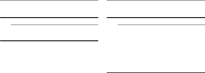
Parts included
All models
7
Models with circulating-air mode
$'
$$
Ducted operation
$'
Accessory: Remote fan unit
$5
8
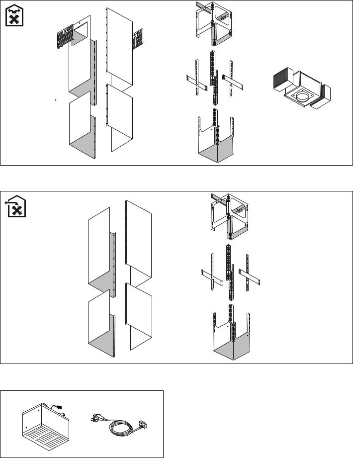
Appliance dimensions
Models with air extraction mode
è¼ʓʘ |
èè¼ʓʘ |
|
|
ç¼ʓʘ |
èç¼ʓʘ |
|
|
ç¼ʚ
ê |
|
|
è¼ʚ |
|
|
èʌ¼ʓʘ ë
èʊ¼ʓʘ |
ç¼ʓʘ |
ë |
|
|
|
|
|
é |
ê |
|
|
|
|
|
|
|
|
Models with air recirculation mode
è¼ʓʘ
 èè¼ʓʘ
èè¼ʓʘ


ç¼ʓʘ |
èç¼ʓʘ |
|
|
||
|
||
|
ç¼ʚ
ê |
è¼ʚ |
|
|
||
|
||
|
èʌ¼ʓʘ ë
èʊ¼ʓʘ |
ç¼ʓʘ |
ë |
|
|
|
||
|
|||
|
|
||
ê |
|
é |
|
|
|
||
|
|
|
PP
PP
9
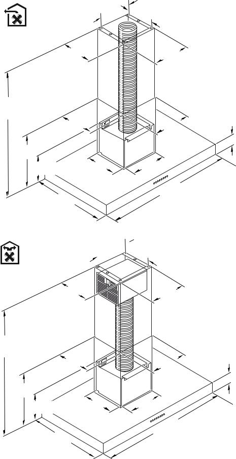
Safety clearances
9WARNING
Risk of fire
Grease deposits in the grease filter may catch fire. The specified safety distances must be observed in order to prevent an accumulation of heat. Observe the specifications for your cooking appliance. If gas and electric cooktops are operated together, the largest specified distance applies.
Only one side of the appliance may be installed directly next to a high-sided unit or a wall. The distance between the appliance and wall or highsided unit must be at least 2" (50 mm).
The minimum distance between the supporting surface for the cooking equipment on the hob and the lowest part of the range hood must be not less than 30 "
(760 mm) from electric cookers and 30 " (760 mm) from gas or mixed cookers.
If the instructions for installation for the gas hob specify a greater distance, this must be adhered to.
DERYH JDV
VXU JD]
VREUH JDV
DERYH HOHFWULF VXU pOHFWULTXH VREUH HOpFWULFR
!
!
Installation
Appliance Handling Safety
Unit is heavy and requires at least two people or proper equipment to move.
Hidden surfaces may have sharp edges. Use caution when reaching behind or under appliance.
Transport securing device
The supporting frame is secured for transport using self-tapping screws. Remove these self-tapping screws before installation.
10
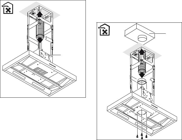
Fitting the upper support frame
1Before installation, establish the total height of the support frame.
Note: The height of the support frame can be adjusted in steps of ¾" (20 mm).
2Mark the positions of the six screws on the ceiling.
Note: Ensure that the support frame is in the correct position. The appliance has one control panel on the open side of the support frame. The other control panel is located on the opposite side.
3Drill the holes and push in the wall plugs so that they are flush with the wall.
4Use six screws to fasten the upper support frame to the ceiling.
Fitting the lower support frame without using an extension
1Ensure that the lower support frame is in the correct position.
Note: Position the open side of the lower support frame opposite the open side of the upper support frame.
2Slide the lower support frame into the upper support frame and use 16 screws to secure it at the established total height.
Notes |
‒Select the mounting holes in such a way that a maximum clearance is achieved between the screws. The purpose of this is to ensure stability.
‒Leave open at least one mounting hole between the screws.
11
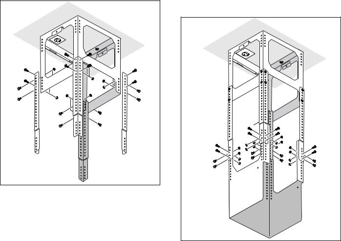
Fitting the lower support frame using an extension
1Slide each part of the extension over the outside of the upper support frame and use 16 screws to fit them to the upper support frame..
2Ensure that the lower support frame is in the correct position.
Note: Position the open side of the lower support frame opposite the open side of the upper support frame.
3Slide the lower support frame up into the extension and use 16 screws to secure it at the established total height.
12
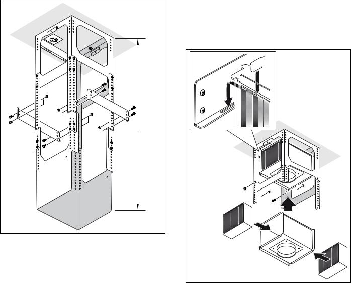
4 Fit two reinforcing brackets.
ʎ¼ʓʘ è¼ʚ |
|
PP |
Installing the appliance
1For recirculation mode units only: Fit filters to both sides of the AA 442 810 air recirculation module. Slide the air recirculation module into the support frame from below and hook it in place. Secure it with two screws.
13
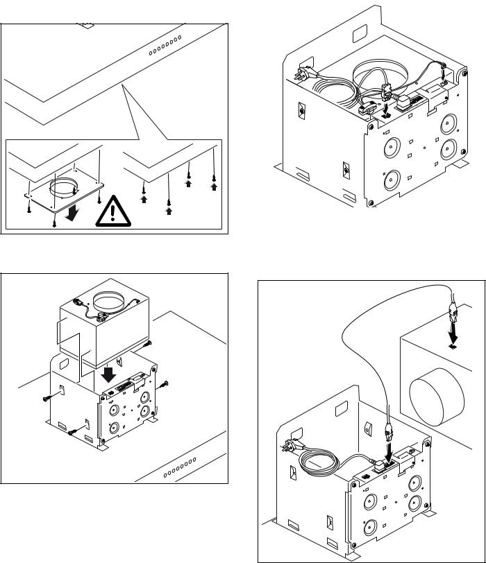
2 For combination with internal remote fan unit |
Connect the mains cable and control cable to the |
||||||||||
AR 400 743 only: Unscrew the cover plate from the |
control module. |
||||||||||
ventilation hood: Loosen the four screws, remove |
|
|
|
|
|
|
|||||
|
|
|
|
|
|
||||||
the cover plate and screw the four screws in again. |
|
|
|
|
|
|
|||||
|
|
|
|
|
|
|
|
|
|
|
|
|
|
|
|
|
|
|
|
|
|
|
|
|
|
|
|
|
|
|
|
|
|
|
|
|
|
|
|
|
|
|
|
|
|
|
|
|
|
|
|
|
|
|
|
|
|
|
|
|
|
|
|
|
|
|
|
|
|
|
|
|
|
|
|
|
|
|
|
|
|
|
|
|
|
|
|
|
|
|
|
|
|
|
|
|
|
|
|
|
|
|
|
|
|
|
|
|
|
|
|
|
|
|
|
|
|
|
|
|
|
|
|
|
|
|
|
|
|
|
|
|
|
|
|
|
|
|
|
|
|
|
|
|
|
|
|
|
|
|
|
|
|
|
|
|
|
|
|
|
|
|
|
|
|
|
|
|
|
|
|
|
|
|
|
|
|
|
|
Slide the remote fan unit into the ventilation hood from above. Use four screws to secure it in place.
3For a combination with external remote fan unit AR4.. only: Use the network cable to connect the external remote fan unit and the ventilation hood’s control module. The plug must snap into place. Connect the mains cable to the control unit.
Note: The X1 and X2 connection sockets are identical.
14
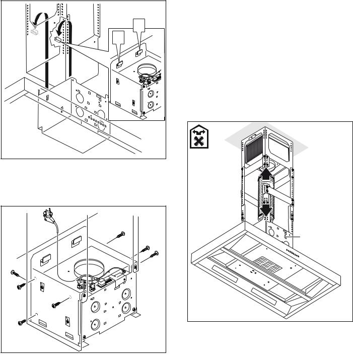
4Slide the ventilation hood up into the support frame from below and hook it into the two angle brackets
(a).
D |
D |
Note: Ensure that the mains cable is not trapped.
5Align the ventilation hood so that it is straight and use seven screws to fasten the ventilation hood to the support frame.
Connect appliance
Notes
‒With operation in extraction air mode , a backpressure flap should be installed. If no backpressure flap is included with the appliance, it can be ordered from a specialist retailer.
‒If the exhaust air is conveyed through the outer wall, a telescopic wall box should be used.
‒If an aluminum duct is used, smooth the connection area beforehand.
Establishing the connection for the exhaust air
1Recirculation mode units with internal remote fan unit AR 400 743: Attach the exhaust air pipe directly to the fan motor's air pipe connector (A).
% |
$ |
$5 |
15
2Extraction mode units with internal remote fan unit AR 400 743: Attach the exhaust air pipe directly to the fan motor's air pipe connector (A).
% |
$ |
$5 |
3Extraction mode units with external remote fan unit AR 4..:
‒Unscrew the connecting pieces from the cover plate in the ventilation hood.
‒Secure the exhaust air pipe to the connecting piece (A).
‒Screw the connecting piece to the cover plate in the ventilation hood.
$5 |
% |
$ |
4Connect it to the air extractor opening (B).
5Seal the joints appropriately.
Connecting the power supply
1Plug the mains plug into the grounded socket.
2If a fixed connection is required, please follow the instructions in the Electrical Connection section.
16

Attaching flue duct |
Models with air recirculation mode |
9 WARNING
Risk of injury
Components inside the appliance may have sharp edges. Wear protective gloves.
1 Remove the protective film from the flue ducts.
2 Place both parts of the upper flue duct on the appliance such that they fit together.
Model with air extraction mode
3 Push the upper flue duct up and use two screws to secure it at the top.
Model with air extraction mode
17 |
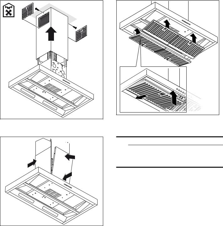
Models with air recirculation mode
4Place both parts of the lower flue duct on the appliance such that they fit together.
5 Fit the grease filter.
Additional switching output
9WARNING
Work must only be carried out on the additional switching output by a qualified electrician in accordance with the country-specific requirements and standards.
The appliance has an additional switching output X16 (potential-free contact) that can be used to connect other appliances, such as a ventilation system that is available at the installation site. The contact is closed when the blower is switched on, and is opened when the blower is switched off.
The switching output is located under a cover. Maximum switching power 30 V/1 A (AC/DC). The signal that is connected to the contact must correspond to class of protection 3.
Connection for window contact switch AA 400 510
Work on the connection for the window contact switch must only be carried out by a qualified electrician in accordance with the requirements and standards of the country in which in the appliance is being used.
The appliance has a connection (X17) for a window contact switch. The window contact switch can be flush mounted or surface mounted. You will receive the
18
Loading...