


 Loading...
Planning notes for the installation of 400 series ovens and Combi-steam oven combinations.
Applies to BO/BX/BS/WS
General notes
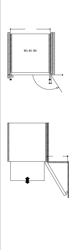
Necessary air openings on the door edges
Installation behind kitchen cabinet doors
Appropriate measures must be taken to prevent these types of doors from closing when the appliance is heating or while it is cooling down (fan operation).
Please check your local regulations.
Combination of ovens and modular refrigeration systems Please check the planning notes in the refrigeration section in order to prevent the refrigerator door from colliding with the oven.
Installation side-by-side When appliances are installed side by side, the clearance
between the appliances must be at least ⅜" (corresponds to the standard outside measurement of the furniture cavity of 23 ⅝" or 30"). For best possible door opening, the door hinges should be positioned outside in order to
use the full available door opening angle. (see picture to the right). Please note: When Sabbath mode is engaged, the automatic door release is deactivated. The use of (optional) handles is recommended in this type of installation.
Gaggenau 400 series ovens are supplied with fresh air for cooling at the top edge and side edges of the door. Hot air is blown out at the door bottom edge. Combi-steam ovens have the air inlet at the side edges of the door and the hot air and steam outlets at the top edge of the door.
In order to prevent appliances from overheating and to ensure that they cool down as required after operation, appropriate minimum cross sections of free space must be maintained from kitchen cabinet edges.
The measurements given in the drawing apply to all appliances. The following should also be checked:
The area above the appliance BS:
No other appliance should be installed above the comb-
steam oven. Where an edge of a kitchen unit protrudes more than ¹³⁄" in front of the edge of the cabinet cavity,the edge of the kitchen cabinet panel must
be steam resistant as is the case above a dishwasher. Steam may possibly penetrate into the shelf compartment.
The area below the appliance WS:
When the warming drawer is operated without handles, pay attention that there is sufficient access to the lower edge of the appliance if the thickness of the
Installation side-by-side
ç¼ɑ
Air openings on the door edges above/below
ɀ¼Ɏ èç¼ɇɌ 

çɥɎ |
è¼Ɏ %2 %6 %0 &0 |
%2 %; %6 %0 &0 :6
ç¼ɇɌ

 èç¼ɇɌ
èç¼ɇɌ
èç¼ɇɌ 


Numbers indicated
inside parenthesis ( ) = mm
6 400 series ovens
kitchen cabinet door is greater than ¹³⁄" in front of the cabinet cavity.
At the sides
In situations where kitchen cabinet doors are thicker, or where sidewalls protrude up to 1 ⁄" from the front of the edge of
the cabinet cavity, the minimum distance on the hinge side is sufficient for the air supply and a door opening angle of 120°. Above that, a distance of ⅜" or
even more is required. The handle side may, if required, be covered by a side panel provided that the minimum distance is maintained.
Installation in corners |
Door clearance at the sides |
|
When the pull-out drawer is |
|
used, a larger door opening |
|
angle of 7 ⅞" is required. For |
|
all other situations, 3 ¹⁄" is |
|
recommended. Where there are |
|
smaller side clearances down to |
|
a minimum of 1 ¹⁄", restrictions |
|
in handling hot baking trays |
|
should be expected and the user- |
|
friendliness of the side-opening |
|
door can not be taken |
|
for granted. |
Air openings on the door edges
ɞ
¼ PD[

 ¼
¼
ç¼
ç¼
ɝ
Installation in corner situation
%2 %; |
|
3XOO RXW GUDZHU |
%$IRU |
%$IRU |
Numbers indicated
inside parenthesis ( ) = mm
400 series ovens 7

Combination options for 400 series ovens and Combi-steam ovens.
This check list provides the most relevant parameters for the perfect combination and ordering of ovens, Combi-steam ovens, fully-automatic coffee machine, warming/storage drawers and dishwashers.
In general:
□All products shown can be obtained with stainless-steel-backed full glass doors.
□When several products are listed (BO/BS), the first model number is shown.
Vertical combinations
When planning and ordering please note that
□The door hinges of the ovens must be on the same side.
□The door hinge (right-/left-hinged) is not reversible.
□The width of the products is identical.
□The control modules of 30" wide ovens should meet each other in the middle of the combination.
□No additional product should be installed above the BS.
□When installing an oven above a dishwasher, only products with controls on top can be used. The cutout for products that are
installed above it must be 22 ¹⁄ " wide. The dishwasher is 24" wide. A stainless-steel-backed full glass door can be obtained as a optional accessory.
Horizontal combinations
When planning and ordering please note that
□The door hinges need to be placed on the outside in order to use the fully available door opening angle.
□The door hinge (right-/left-hinged) is not reversible.
□A minimum clearance of ⅜" between the two doors must be observed.
□Combi-steam ovens and fullyautomatic coffee machine in combination with a WS 461 warming drawer (5½" in height) have the same total height as a 24" wide oven and they share the same cut-out. In a combination with the WS 463 Warming/ storage drawer an intermediate shelf is required.
BO Ovens
BS Combi-steam ovens
CM Fully-automatic coffee machine WS Warming/storage drawers
DF Dishwashers
Vertical combination, 30" wide products
•BS 484 / BS 464 |
•BX 480 |
•BO 480 |
•WS 482 |
•WS 482 |
|
Horizontal combination, 30" wide products
•BO 481 |
•BO 480 |
Vertical combination, 24" wide products
•BS 470 |
•BS 471 |
•BO 450 |
•CM 210 |
•WS 461 |
•WS 461 |
Combination of 4, 30" wide products
•BS 485 / BS 465 |
•BS 484 / BS 464 |
•BO 481 |
•BO 480 |
•BO 481 |
•BS 484 / BS 464 |
|
•WS 482 |
•BS 470 •BO 450 •WS 463
•BO 450 |
•BS 470 |
•DF |
•DF |
4 400 series ovens

Horizontal combination, 24" wide products
•BO 451 |
•BO 450 |
•BO 451 |
•BS 470 |
•BO 451 |
•CM 210 |
|
|
|
•WS 461 |
|
•WS 461 |
•BS 471 |
•BS 470 |
•BS 471 |
•CM 210 |
•WS 461 |
•WS 461 |
•WS 461 |
•WS 461 |
•BO 451 |
•BS 470 |
•CM 210 |
•BS 471 |
•BS 470 |
•CM 210 |
|
•WS 461 |
•WS 461 |
•WS 461 |
•WS 461 |
•WS 461 |
Combination of 4 with 24" wide products
•BS 471 |
•BS 470 |
•BO 451 |
•CM 210 |
|
•WS 461 |
Horizontal combination, 30" and 24" wide products
•BO 481 |
•BS 470 |
•BO 481 |
•BS 470 |
•CM 210 |
|
•WS 463 |
|
•WS 463 |
•WS 463 |
400 series ovens 5
Gaggenau |
|
Installation instructions .......................... |
1 |
Instructions d’installation..................... |
10 |
Instrucciones de instalación ................ |
19 |
BO 450/451 610 BO 480/481 610
Oven
Four
Horno

Safety Definitions
9WARNING
This indicates that death or serious injuries may occur as a result of non-observance of this warning.
9CAUTION
This indicates that minor or moderate injuries may occur as a result of non-observance of this warning.
NOTICE: This indicates that damage to the appliance or property may occur as a result of non-compliance with this advisory.
Note: This alerts you to important information and/or tips.
2

9 IMPORTANT SAFETY INSTRUCTIONS
READ AND SAVE THESE INSTRUCTIONS
WARNING
If the information in this manual is not followed exactly, fire or shock may result causing property damage or personal injury.
WARNING
Do not repair, replace or remove any part of the appliance unless specifically recommended in the manuals. Improper installation, service or maintenance can cause injury or property damage. Refer to this manual for guidance. All other servicing should be done by a qualified technician.
State of California Proposition 65
Warnings
WARNING
This product contains chemicals known to the State of California to cause cancer, birth defects or other reproductive harm.
Appliance Handling Safety
Unit is heavy and requires at least two people or proper equipment to move.
Do not lift appliance by door handle.
Hidden surfaces may have sharp edges. Use caution when reaching behind or under appliance.
Safety Codes and Standards
This appliance complies with the latest version of one or more of the following standards:
CAN/CSA C22.2 No. 61 - Household Cooking Ranges
UL 858 - Household Electric Ranges
CAN/CSA C22.2 No. 150 - Microwave Ovens
UL 923 - Microwave Cooking Appliances
CSA C22.2 No. 64 - Household Cooking and Liquid-Heating Appliances
UL 1026 - Electric Household Cooking and Food Serving Appliances
It is the responsibility of the owner and the installer to determine if additional requirements and/or standards apply to specific installations.
Electric Safety
Before you plug in an electrical cord, be sure all controls are in the OFF position.
If required by the National Electrical Code (or Canadian Electrical Code), this appliance must be installed on a separate branch circuit.
Installer - show the owner the location of the circuit breaker or fuse. Mark it for easy reference.
Important - save these instructions for the local electrical inspector’s use..
Before installing, turn power OFF at the service panel. Lock service panel to prevent power from being turned ON accidentally.
Refer to data plate for more information. See “Data Plate” under “Service” for data plate location.
Be sure your appliance is properly installed and grounded by a qualified technician. Installation, electrical connections and grounding must comply with all applicable codes.
Related Equipment Safety
Remove all tape and packaging before using the appliance. Destroy the packaging after unpacking the appliance. Never allow children to play with packaging material
Never modify or alter the construction of the appliance. For example, do not remove leveling legs, panels, wire covers or anti-tip brackets/screws.
3
9 IMPORTANT SAFETY INSTRUCTIONS
READ AND SAVE THESE INSTRUCTIONS
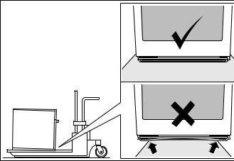
Transport
To avoid damage to the oven vent, use the transport method shown in the picture below.
4

Before You Begin
Tools and Parts Needed
Philips head screwdriver
1/8" drill bit and drill
Measuring tape
Parts Included
Built-in oven
3 Torx screws
Power Requirements
The outlet must be properly grounded in accordance with all applicable codes.
Planning notes
Door hinge not interchangeable.
Distance from furniture body to door front 1.85” (47 mm).
Distance from furniture body to outer edge of door handle 3.7” (94 mm) after retrofitting the handle (special accessory).
Pay attention to the front protrusion, possibly including the door handle, for opening drawers at the sides.
When planning a corner solution, pay attention to the door opening angle of at least 90°.
Preparing kitchen units
Kitchen units must be temperature-resistant up to 195° F (90 °C) and adjoining furniture frontages up to 160° F (70 °C).
Ventilation cut-out in the built-in cupboard's intermediate shelf: at least 0.8 in to 1.65 ft (20 x 500 mm).
The wall socket must be outside the built-in niche.
Cut recesses on the furniture before inserting the appliance. Remove any shavings, as these can affect the operation of electrical components.
Secure unsecured furniture items to the wall using a commercially available bracket.
Only install the appliance so high that accessories can be removed with ease.
5
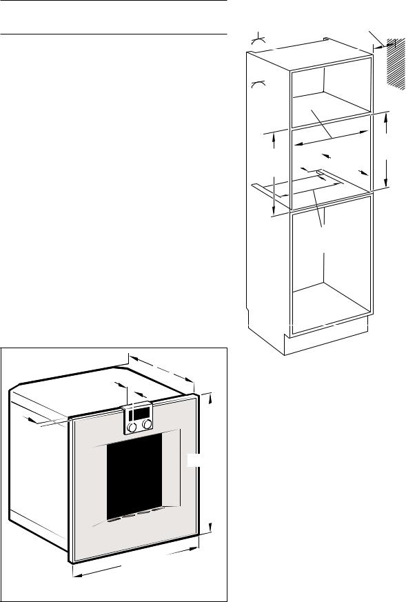
Dimensions and Cabinet
Requirements
Cabinet Dimensions
PLQ
ZLWK DYHF FRQ %$PLQ
General Cabinet Requirements |
|
|
|
|
|
|
|
Cabinet requirements vary depending on the model to |
|
|
|
|
|
|
|
|
|
|
|
|
|
|
|
be installed. Please consult the section Dimensions |
|
|
|
|
|
|
|
for the details pertaining to your particular model. |
|
|
|
|
|
||
|
|
|
|
|
|
||
All models require: |
|
|
|
|
|
||
|
|
|
|
|
|||
|
|
|
|
|
|||
¼" (6.4 mm) space between the side of the |
PLQ |
|
|
|
|||
appliance and an adjacent wall or cabinet door |
|
|
PLQ |
|
|||
|
|
|
|||||
when intalled at the end of a cabinet run. |
|
|
|
|
|||
|
|
|
|
|
|
||
|
|
|
|
|
|
|
|
The cabinet base must be flat and capable of |
|
|
|
|
|
|
|
supporting the weight of your appliance when in |
|
|
|
|
|
|
|
use. See the appropriate weight for your model in |
|
|
|
|
|
|
|
the Dimensions section pertaining to your |
|
|
|
PLQ |
|
|
|
particular model. |
|
|
|
|
|
|
|
|
|
|
|
|
|
|
|
Dimensions for 24” Wall-Mounted
Units
BO 450/451-610
Appliance Dimensions
|
|
||||||||
|
|
|
|
|
|
|
|
||
|
|
|
|
|
NOTICE: The cabinet base must be flat and capable of |
||||
|
|
|
|||||||
|
|
|
|||||||
|
|
||||||||
|
|
|
|
|
|
|
|
|
supporting a weight of at least 142 lbs (64.1 kg). |
|
|
|
|
|
|
|
|
|
|
|
|
|
|
|
|
|
|||

|
|
PP
6
Loading...