


 Loading...
Back
MARINE VHF RADIOTELEPHONE
FM-2721

9-52 Ashihara-cho,
Nishinomiya, Japan
Telephone : 0798-65-2111
Telefax : 0798-65-4200
All rights reserved. |
Printed in Japan |
PUB.No. OME-56163
( HIMA ) FM-2721
Your Local Agent/Dealer
FIRST EDITION : MAR. 2000
E : FEB. 22,2002
*00080897300*
*00080897300*
* 0 0 0 8 0 8 9 7 3 0 0 *
*OME56163E00*
*OME56163E00*
* O M E 5 6 1 6 3 E 0 0 *

DISTRESS Call Procedure
Do the following when a life endangering situation arises on your vessel:
1.Hook off the handset.
2.Press the [POWER] switch in the hanger to turn on the unit if it is not already on.
3.Open the DISTRESS button lid in the hanger and press the [DISTRESS] button about three seconds to show the following display, then release the button.
D i s t r e s s c a l l i n p r o g r e s s
D I S T R E S S C A L L
N a t u r e :
U N D E S I G N A T E D
P o s : |
1 2 : 3 4 |
1 2 ˚ 3 4 E 1 2 3 ˚ 4 5 N
4.The equipment displays “Wait for Ack Auto re-Xmit” while waiting for acknowledgment of the distress call. (Transmitting repeats with 3.5 to 4.5 minutes interval until pressing [Cancel] key.
5.When you receive the distress acknowledgement call, you are automatically connected to CH16. Hook off the handset if it is not already off hook. Press the PTT switch and say:
a)MAYDAY three times.
b)This is [name of your vessel].
c)MAYDAY
d)This is [name of your vessel].
e)Position
f)Nature of Distress
g)Kind of assistance needed
h)Number of crew
i)Other info such as description of your vessel
j)Over.
i

Receiving Distress Alert from Other Ship
General
When the FM-2721 receives a distress alert from other vessel the LED (Red) lights and the FM-2721 sounds the distress alarm.
1.Silence the alarm by pressing the [Cancel] key (or wait for two minutes).
2.Press the [Log] key to show the Sel. Log file menu.
3.Select Rcvd. DISTRESS, and then press the [Enter] key to view the contents of the distress message.
4.Wait up to three minutes until the DIST ACK signal from a coast station is received.
5.Open the Rcvd. DISTRESS file again.
6.Be prepared to follow the instructions of the coast station.
If you do not receive the DIST ACK signal, follow the flow chart shown on the next page.
The DIST ACK by voice can be transmitted by you under certain conditions. Please carefully read and follow the flow chart to determine whether you should transmit it or not.
When receiving a distress alert, the LCD display appears as shown right.
|
INTL |
|
SIMP |
25W |
|
|
Rx |
16 |
|
|
|
|
Lat: |
45.23 |
N |
||
|
Lon:121.88 |
E |
|||
|
Time:10:57UTC |
||||
|
VOL:08 |
|
SQ:03 |
||
|
RCVD. DISTRESS |
||||
|
<Hand set on hook> |
||||
|
|
|
|
|
|
|
INTL |
|
SIMP |
25W |
|
|
SCAN |
|
16 |
|
|
|
Rx |
|
|
|
|
|
VOL:08 |
|
SQ:03 |
||
RCVD. DISTRESS
<Hand set off hook>
ii

Should I transmit DIST ACK by voice or not?
Distress alert received.
Press the [Cancel] key to silence alarm.
Read DISTRESS message.
|
Acknowledge |
No |
||||
received from coast station? |
|
|
||||
|
|
|||||
|
(Wait 3 mins.) |
|
|
|||
|
Is |
|||||
|
|
|
Yes |
|||
|
|
|
your vessel |
|||
|
|
|
|
|
near vessel in |
|
|
|
|
|
|
||
|
Press the [Cancel] key |
|
distress? |
|||
|
to silence alarm. |
|
|
|
||
|
|
|
|
|
|
|
|
|
|
|
|
|
|
|
|
|
|
|
|
|
|
Successively to |
|
|
|
||
|
check receive |
|
|
No |
||
|
message contents. |
|
|
|
||
|
|
|
|
|
|
|
|
|
|
|
|
|
|
|
|
|
|
|
||
|
Continue watch on |
|
|
|
||
|
CH 16 until you hear |
|
|
|
||
|
[SEELONCE FINI], |
|
|
|
||
|
which means complet- |
|
|
|
||
|
ion of distress commu- |
|
|
|
||
|
nication. |
|
|
|
||
|
(Follow instructions of |
|
|
|
||
|
coast station.) |
|
|
|
||
|
|
|
|
|
|
|
Yes
If you can assist the vessel  in distress, transmit acknowledge by voice to vessel in distress on CH 16.
1.Say "MAYDAY" ... Once
2.Say ID number of vessel in distress ... 3 times
3.Say "This is" ... Once
4.Say ID number of your vessel
... 3 times
5.Say "Received MAYDAY" ... Once
iii


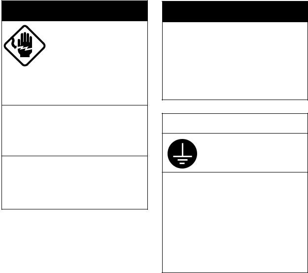
 SAFETY INSTRUCTIONS
For the operator
 CAUTION
Do not open the equipment.
Only qualified personal should work inside the equipment.
Do not disassemble or modify the equipment.
Fire, electrical shock or serious injury can result.
Turn off the power immediately if waterleaks into the equipment or the equip-ment is emmitting smoke or fire.
Continued use of the equipment can cause fire or electrical shock.
Any repair work must be done by a licensed radio technician.
Improper repair work can cause electrical shock or fire.
 CAUTION
Handle the handset carefully.
Rough handling may affect its watertight integrity.
Distances at which radiation levels of
100 and 10 W/m2 exist are given in the table.
Distance to |
Distance to |
100 W/m2 point |
10 W/m 2 point |
0.12 m |
0.39 m |
iv
For the installer
 WARNING
ELECTRICAL SHOCK HAZARD
Do not open the equipment unless totally familiar with electrical circuits and service manual.
Only qualified personnel should work inside the equipment.
Turn off the power at the switchboard before beginning the installation.
Fire or electrical shock can result if the power is left on.
Do not install the equipment where it may get wet from rain or water splash.
Water in the equipment can result in fire, electrical shock or equipment damage.
 WARNING
Be sure that the power supply is compatible with the voltage rating of the equipment.
Connection of an incorrect power supply can cause fire or equipment damage. The voltage rating of the equipment appears on the label above the power connector.
 CAUTION
Ground the equipment to prevent electrical shock and mutual interference.
Observe the following compass safe distances to prevent interference to a magnetic compass:
|
Standard |
Steering |
|
|
compass |
compass |
|
|
|
|
|
Transceiver |
0.95 m |
0.65 m |
|
unit |
|||
|
|
|
|
Handset and |
2.05 m |
1.40 m |
|
bracket |
|||
|
|
||
|
|
|
|
Loundspeaker |
2.20 m |
1.50 m |
|
|
|
v

Table of Contents
DISTRESS Call Procedure................................ |
i |
|
Receiving Distress Alert from Other Ship...... |
ii |
|
SAFETY INSTRUCTIONS................................ |
iv |
|
System Configuration .................................. |
viii |
|
Equipment Lists.............................................. |
ix |
|
Introduction..................................................... |
xi |
|
1. Installation.................................................... |
1 |
|
1.1 |
Mounting ............................................................. |
1 |
1.2 |
Transceiver Connections..................................... |
5 |
1.3 |
Handset Connection............................................ |
9 |
2. Controls ...................................................... |
10 |
|
2.1 |
Controls, Indications, LEDs............................... |
10 |
3. VHF Telephone Operation .......................... |
14 |
|
3.1 |
Turning the Power On/Off.................................. |
14 |
3.2 Listening for Telephony Calls ............................ |
14 |
|
3.3 Adjusting the Dimmer, Contrast......................... |
14 |
|
3.4 |
Selecting USA, INT, WX Channel...................... |
15 |
3.5 |
Selecting Channel ............................................. |
15 |
|
3.6 Adjusting Squelch.............................................. |
15 |
||
3.7 Adjusting Loudspeaker Volume ......................... |
16 |
||
3.8 |
Muting the Loudspeaker .................................... |
16 |
|
3.9 |
Setting Transmitter Power ................................. |
16 |
|
3.10 |
Receiving a Telephone Call ............................. |
16 |
|
3.11 Making a Telephone Call.................................. |
17 |
||
3.12 |
Dual Watch ...................................................... |
17 |
|
3.13 |
Starting/Stopping Scanning ............................. |
17 |
|
3.14 |
Intercom .......................................................... |
18 |
|
3.15 |
Keyboard Lock ................................................ |
18 |
|
4. DSC Operation ............................................ |
19 |
|
4.1 |
Distress Call ...................................................... |
19 |
4.2 |
Distress Call by [Call] key.................................. |
20 |
4.3 |
Sending DSC Call to a Ship .............................. |
21 |
4.4 |
Sending DSC Call to a Coast Station ................ |
22 |
4.5 |
Sending PSTN Call to a Shore Station .............. |
23 |
4.6 |
Sending a Group DSC Call................................ |
25 |
4.7 |
Sending an All Ships Call ................................. |
26 |
4.8 |
Receiving DSC Calls ......................................... |
27 |
vi
4.9 |
Manual Entry of Position and Time.................... |
28 |
4.10 Storing IDs ...................................................... |
29 |
|
4.11 Storing Telephone Numbers ............................ |
30 |
|
4.12 Storing Messages ........................................... |
31 |
|
4.13 Message Log................................................... |
33 |
|
5. Maintenance ............................................... |
35 |
|
5.1 Antenna Check.................................................. |
35 |
|
5.2 |
Cleaning of Transceiver, Handset ..................... |
35 |
5.3 |
Fuse Replacement ............................................ |
35 |
5.4 |
Battery Check.................................................... |
35 |
6. Troubleshooting ......................................... |
36 |
|
6.1 |
Easy Troubleshooting........................................ |
36 |
6.2 |
Diagnostics........................................................ |
38 |
6.3 |
Self check Messages ........................................ |
39 |
6.4 |
Menu Tree......................................................... |
40 |
Appendix ........................................................ |
41 |
|
How to fabricate the cable for optional connector |
|
|
17JE-23250-02/17JE-23090-02 .............................. |
41 |
|
VHF Channel Frequencies (Marine and Inland |
|
|
waterways).............................................................. |
42 |
|
VHF Weather Channel Frequencies ....................... |
46 |
|
PRIVATE CHANNELS (U.K. MARINERS)............... |
47 |
|
PRIVATE CHANNELS (NORDIC)............................ |
47 |
PRIVATE CHANNELS (NETHERLANDS-INLAND). 47 |
|
General Notes on Operating Marine VHF...... |
48 |
Rules and Manners ................................................. |
48 |
Communication Distance......................................... |
49 |
Specifications ............................................. |
SP-1 |
Packing Lists ................................................ |
A-1 |
Outline Drawings .......................................... |
D-1 |
Schematic Diagram ...................................... |
S-1 |
Declaration of Conformity |
|
vii
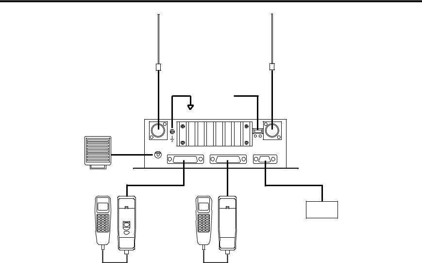
System Configuration
(150M-W2VN)
VHF & CH70 RX ANT
(OPTION)
(150M-W2VN)
CH70 RX ANT
(OPTION)
|
|
(5D-2V) |
|
|
12V DC |
(5D-2V) |
|
||
|
|
|
|
|
|
|
|||
|
|
|
GROUND |
|
|
|
|
||
SPEAKER |
|
|
|
|
|
|
|
TRANSCEIVER |
|
|
|
|
|
|
|
+ - |
|
||
|
|
|
|
|
|
12VDC |
|
UNIT |
|
|
|
ANT |
|
|
|
|
CH70 |
||
(OPTION) |
SPKR |
|
|
|
|
RX ANT |
FM-2721 |
||
REMOTE 1 |
REMOTE 2 |
IEC61162-1(NMEA) |
|||||||
|
|||||||||
|
|
|
|
||||||
(SEM-21Q) |
|
|
5m |
MAX 50m |
|
|
|
|
|
|
|
|
|
|
GGA,RMC,GLL,ZDA |
||||
|
|
|
|
(OPTION) |
|
|
|||
(HS-2721) |
(RB-2721A) |
|
(HS-2721) |
(RB-2721B) |
(IEC61162-1) |
||||
|
|
|
|||||||
NAV device
DISTRESS
POWER
REMOTE HANDSET A |
REMOTE HANDSET B |
(OPTION)
viii
Equipment Lists
Standard Supply
Name |
Type |
Code No. |
Qty |
Remarks |
|
|
|
|
|
Handset |
HS-2721 |
- |
1 |
|
|
|
|
|
|
Transceiver Unit |
FM-2721 |
- |
1 |
|
|
|
|
|
|
Bracket |
RB-2721A |
- |
1 |
For handset |
|
|
|
|
|
Installation |
CP05-08000 |
000-057-744 |
1 set |
|
Materials |
|
|
|
|
|
|
|
|
|
Spare Parts |
SP05-01600 |
004-542-060 |
1 set |
10A Fuse: 2 pcs |
|
|
|
|
|
ix
Optional Supply (cont.)
Name |
Type |
Code No. |
Qty |
Remarks |
|
Bracket |
RB-2721B |
000-057-738 |
1 set |
|
|
|
RB-2721A |
000-057-737 |
1 set |
|
|
Handset |
HS-2721 |
|
000-057-736 |
1 set |
|
Antenna Kit |
AP05-00810 |
000-057-722 |
1 set |
RA106 |
|
Antenna Kit |
AP05-00820 |
000-057-723 |
1 set |
150M-W2VN |
|
Antenna Kit |
AP05-00900 |
000-057-739 |
1 set |
396-1 |
|
Loudspeaker |
SEM-21Q |
000-144-917 |
1 |
|
|
Twisted 10 pair |
05S0308 |
*5 M* |
000-107-578 |
|
5 m |
Cable |
05S0308 |
*10 M* |
000-106-038 |
|
10 m |
|
|
||||
|
05S0308 |
*20 M* |
000-106-039 |
1 |
20 m |
|
05S0308 |
*30 M* |
000-106-040 |
|
30 m |
|
05S0308 |
*40 M* |
000-106-041 |
|
40 m |
|
05S0308 |
*50 M* |
000-106-042 |
|
50 m |
Connector |
17JE-23250-02 |
000-120-946 |
1 |
For 05S0308 |
|
|
(D8C) |
|
|
|
(REMOTE2) |
Connector |
17JE-23090-02 |
000-132-624 |
1 |
For IEC61162-1 |
|
|
(D8C) |
|
|
|
(NMEA) |
DC-DC Converter |
PC-208A |
|
000-142-469 |
1 |
|
CH-70 Antenna Kit |
OP05-92 |
|
005-376-120 |
1 set |
Connector assy. |
|
|
|
|
|
|
x

Introduction
A Word to the Owner of the FM-2721
Congratulations on your choice of the FURUNO FM-2721 Marine VHF Radiotelephone. We are confident that you will enjoy many years of trouble-free operation with this fine piece of equipment.
For more than 50 years FURUNO Electric Company has enjoyed an enviable reputation for quality and reliability throughout the world. This dedication is furthered by our extensive global network of agents and dealers.
Your equipment is designed and constructed to provide commercial grade performance and reliability, yet is affordable for pleasure craft owners.
Please carefully read this manual and follow the recommended procedure for installation, operation and maintenance. With proper care, your equipment should provide years of enjoyable and dependable communications.
Thank you for considering and purchasing FURUNO.
xi
Features
•25 W radiotelephone with control in palm
•Intercom facility
•Compact transceiver unit allows installation where space is limited
•ATIS (Automatic Transmitter Identification System) mode enables use of the radiotelephone on inland waterways, also use with the class D DSC (ID registrations required).
•“Dual watch” monitors CH16 while watching on another channel.
•Extensive message storage
•Conforms to the following regulations
•European Standard EN 301 025 (VHF with Class D DSC)
•European Standard EN 300 698 (VHF used on inland waterways)
•ITU Radio Regulations Appendix 18: Table of transmitting frequencies 156 – 174 MHz for stations in the mobile service
•ITU-T Recommendation E.161: Arrangements of digits, letters and symbols on
telephones and other devices that can be used for gaining access to a telephone network
•IEC61162-1: Maritime navigation and radiocommunication equipment and Systems – Digital Interface Part 1: Single and multiple listeners
•MSC/Circ.803: Participation of non-SOLAS ships in the Global Maritime Distress and Safety System
•ITU-R Recommendation M.493-9: Digital selectivecalling system for use in maritime mobile service
xii

1. Installation
1.1 Mounting
Transceiver unit
The transceiver unit can be mounted on the overhead, a desktop or on a bulkhead. Select the mounting location considering the following:
•It is recommended to install the equipment in the cabin so as to avoid spray.
•The equipment should be located as near to the power source as possible, and as far apart as possible from any devices that may cause interference such as direction finders, navigation receivers and other onboard electronics.
•Compass safe distances (Standard compass, Steering compass) are;
|
Standard |
Steering |
|
|
|
Transceiver unit |
0.95 m |
0.65 m |
|
|
|
Handset and Bracket |
2.05 m |
1.40 m |
|
|
|
Loudspeaker (option) |
2.20 m |
1.50 m |
|
|
|
•The cabinet of the equipment, especially the rear panel, gets warm after a long transmission. Therefore, provide some space around the unit to allow for circulation of cooling air.
•The unit can be mounted on the deck or a bulkhead. The mounting location should be able to support the weight of the unit.
•If necessary, reinforce the mounting location by doubling plate.
•Fasten the unit with four tapping screws (supplied).
1

• For bulkhead mounting, tighten upper tapping |
bulkhead, and screw slots of the unit. Then fasten |
screws (supplied) and washers so there is 5 mm |
upper screws and washers. |
clearance between bottom of screw head and |
|
240 |
|
|
14 |
|
74 |
|
140 |
200
4-  5 Fixing Hole
Transceiver unit, top and side view
2

Handset (Hanger)
The length of the hanger cable is 5 m (optional HS-2721/RB-2721B: 50 m), so locate the handset hanger within 5 m of the transceiver unit.
|
(77) |
65 |
57 |
208
hole |
22 |
42 |
Cable entrance |
|
145+0.5 |
12 |
|
|
2-  4.5 Fixing hole
Remove six screws to remove the hanger cover, and fasten the hanger with two tapping screws (supplied) on the desktop or bulkhead.
Note: The magnet inside the hanger may pull the screwdriver when mounting the hanger.
3
Antenna Connection (option)
Provide a location as high and clear as possible, free from the influence of nearby antenna, rigging and masts.
However, any good quality antenna, complying with the following requirements, may be arranged locally. A high-gain antenna is preferable. If you are not sure, consult with your dealer.
Frequency range: 155 MHz to 164 MHz
Impedance: |
50 ohms |
Polarization: |
Vertical |
Input power: |
25 W |
Quality: |
Able to withstand marine environment |
Any 50 ohm coaxial cable heavier than 5D-2V or RG58C/U may be used for the connection between the antenna and the transceiver unit. Make sure to leave some slack in the cable loop behind the transceiver for service and maintenance ease.
Lay the antenna, and then solder the M-type connector onto the cable end as shown on page 7.
4

1.2 Transceiver Connections
HS-2721 |
RB-2721A |
|
|
|
|
|
|
|
ANT |
|
|
|
|
CH70 RX ANT |
|
|
Connect the optional antenna. |
|
|||||
|
|
|
Ground |
|
Connect the optional CH70 RX antenna. |
||
|
|
|
|
|
|
||
|
|
|
|
Transceiver Unit |
|
|
|
|
|
|
|
FM-2721 |
|
|
|
|
SPKR |
|
|
|
|
|
|
|
Connect the |
|
|
|
|
|
|
|
optional |
|
|
|
12 VDC |
RX ANT |
|
|
|
|
ANT |
|
CH70 |
IEC61162-1 (NMEA) |
|
|
loudspeaker. |
SPKR |
REMOTE 1 |
REMOTE 2 |
IEC61162-1(NMEA) |
||
|
|
|
|
|
|
Connect the navigator. |
|
|
|
|
|
|
|
|
|
Remote 1
Connect the handset bracket.
12VDC
Connect the power cable (05S0388, option).
Ship's mains
Remote 2
Connect the optional handset bracket.
5

Power Connection
Connect the power cable to the connector attached at the rear of the transceiver unit. The RED wire and the BLACK wires, with inline fuses (10A), connect the transceiver unit to the ship’s 12 VDC power supply.
Note:The power cable supplied is 3 meters in length; however it could be shortened as much as possible to prevent power loss.
Remote1, 2
Connect the 10P cable (supplied) here.
Ground ( )
)
While special grounding is not generally required for VHF radiotelephones, it is a good practice to properly ground all electronic equipment to the ship’s ground system. The FM-2721 can be connected to ground by attaching a wire to the ground screw on the transceiver unit’s rear panel and then to the nearest ship’s ground connection point.
ANT
Connect the antenna cable (option) here. Use the optional antenna kit (RG-58/C/U cable).
6
Lay the coaxial cable and attach an M-type plug (if necessary) to the cable as right.
1.Remove the sheath by 30 mm.
2.Bare 23 mm of the center conductor. Trim braided shield by 5 mm
Sheath
and tin.
3.Slide coupling ring onto cable.
4.Screw the plug assembly on the cable.
5. Solder plug assembly to braided shield through solder holes. Solder contact sleeve to conductor.
6.Screw coupling ring into plug assembly.
7.Screw the plug into the ANT connector at the rear of the main unit.
30 mm
5 mm 
 2 mm
2 mm
Conductor
Insulator
Contact sleeve
|
|
|
|
|
|
|
|
|
|
|
|
|
|
|
|
|
|
|
|
|
|
|
|
|
|
|
|
|
|
|
|
|
|
|
|
|
|
|
|
|
|
|
|
|
|
|
|
|
|
|
|
|
|
|
|
|
|
|
|
|
|
|
|
|
|
Cut conductor here. |
|
|
|
|
|
|
|
|
Solder both |
|
||||||||
Coupling ring |
|
|
|
|
||||||||||||
|
sides of hole. |
|
|
|
||||||||||||
7
CH70 RX ANT
Connect the optional CH70 RX antenna kit. For detail, ask your dealer.
SPKR
Connect the optional loudspeaker here.
IEC61162-1 (NMEA)
Connects navigator here. The FM-2721 can input/output the following sentences in NMEA/IEC61162-1 format. Use the 17JE-23090 connector (option) and interconnection cable type EV-SA7/0.16TAx2P (local supply).
(Input):
•GLL: Latitude and longitude
•RMC: Generic navigation information
•GGA: GPA position, UTC
•ZDA: UTC, day, month, and year
(Output):
•TLL: Target data (Outputs the position data of the ship in distress to the navigation device, for example, plotter, connected.)
8
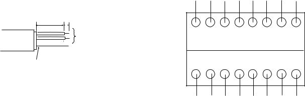
1.3 Handset Connection
Take appropriate measures to ensure water does not leak through hole in bulkhead made for handset cable.
10P cable between the hanger and transceiver unit
10P cable (supplied, 5 m) should be fabricated as below.
GRN/ BLU/ ORG/ YEL/
BRW RED ORG YEL WHT WHT WHT BLK
80 6
Anticorrosive
Sheath
Connect to the appropriate terminal block in the hanger.
Connect to the terminal block #16 in the hanger.
Drain wire
Cable Fablication
1 |
2 |
3 |
4 |
5 |
6 |
7 |
8 |
9 |
10 |
11 |
12 |
13 |
14 |
15 |
16 |
Push the appropriate switch down to insert/pull out the cable.
Drain wire should be covered by vinyl sheath, or soldered to the shield in the cable to be grounded.
Not used cables: Cutt off.
WHT |
BLK GRN BLU PPL WHT BLK Drain |
(B) |
(B) |
Terminal Block Arrangement
Pass the above cable through the entrance hole at the back of the hanger, and attach to the appropriate block. Cover the hole with soft putty from the inside of the hanger.
Handset cable
Connect to the connector at the bottom of the hanger.
9
Loading...