


 Loading...
Back
MARINE RADAR
 FAR/FR-2805 Series
Radar |
ARPA |
Bacic Spec. |
( ) FR-2815 |
( ) FAR-2815 |
X-band, 12 kW, TR up |
( ) FR-2825 |
( ) FAR-2825 |
X-band, 25 kW, TR up |
( ) FR-2855 |
( ) FAR-2855 |
X-band, 50 kW, TR up |
( ) FR-2825W |
( ) FAR-2825W |
X-band, 25 kW, TR down |
( ) FR-2855W |
( ) FAR-2855W |
X-band, 50 kW, TR down |
( ) FR-2835S |
( ) FAR-2835S |
S-band, 30 kW, TR up |
( ) FR-2835SW |
( ) FAR-2835SW |
S-band, 30 kW, TR down |
( ) FR-2865SW |
( ) FAR-2865SW |
S-band, 60 kW, TR down |
|
( ) FA-2805 |
Add-on ARPA |
|
|
|

C
9 - 5 2 , A s h i h a r a - c h o , N i s h i n o m i y a , J a p a n
T e l e p h o n e : |
0 7 9 8 |
- 6 5 |
- 2111 |
T e l e f a x : |
0 7 9 8 - 6 5 - 4 2 0 0 |
||
A l l r i g h t s r e s e r v e d . Printed in Japan
|
P U B . N o . O M E -3 4 0 4 0 |
( Y O S H ) |
F A R / F R - 2 8 0 5 S E R I E S |
 Y o u r L o c a l A g e n t / D e a l e r
F I R S T E D I T I O N : |
A U G . |
1 9 9 5 |
|
X 2 |
: |
F E B . |
2 2 , 2 0 0 2 |


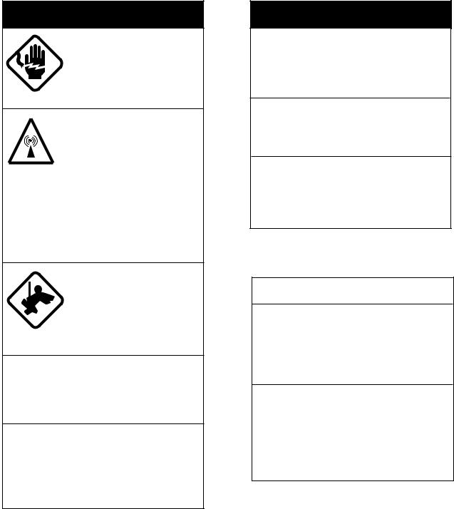
 SAFETY INSTRUCTIONS
 DANGER
Before turning on the radar, make sure that there is no one near the scanner unit.
Serious injury or even death may result if a rotating antenna strikes someone standing nearby.
 WARNING
Radio Frequency Radiation Hazard
The radar antenna emits electromagnetic radio frequency (RF) energy which can be harmful, particularly to your eyes. Never look directly into the antenna aperture from a close distance while the radar is in operation or expose yourself to the transmitting antenna at a close distance.
Model |
Radiator |
Distance to |
Distance to |
RF power density on |
|
type |
100 W/m2 point |
10 W/m2 point |
antenna aperture |
||
|
|||||
|
|
|
|
|
|
|
XN12AF (4') |
|
|
11.0 W/m2 |
|
FR-2815 |
|
Worst case |
Worst case |
|
|
XN20AF (6.5') |
9.6 W/m2 |
||||
(X-band, 12 kW) |
0.25 m* |
2.3 m* |
|||
|
|
||||
|
XN24AF (8') |
|
|
9.6 W/m2 |
|
|
|
|
|
|
|
|
XN12AF (4') |
|
|
29.0 W/m2 |
|
FR-2825/2825W |
|
Worst case |
Worst case |
|
|
XN20AF (6.5') |
23.8 W/m2 |
||||
(X-band, 25 kW) |
0.6 m* |
3.25 m* |
|||
|
|
||||
|
XN24AF (8') |
|
|
23.8 W/m2 |
|
|
|
|
|
|
|
FR-2855/2855W |
XN3A (6.5') |
Nil |
2.0m |
76.0 W/m2 |
|
X-band,50KW |
|
|
|
|
|
XN4A (8') |
Nil |
1.9m |
64.0W/m2 |
||
|
|||||
|
|
|
|
|
|
|
XN5A (10') |
Nil |
1.8m |
50.0W/m2 |
|
|
|
|
|
|
|
FR-2835S/2835SW |
SN30AF (10') |
Nil |
1.06 m |
20.0 W/m2 |
|
(S-band, 30 kW) |
|
|
|
|
|
SN36AF (12') |
Nil |
0.5 m |
16.0 W/m2 |
||
|
|||||
|
|
|
|
|
|
FR-2865SW |
SN30AF (10') |
Nil |
1.2 m |
46.0 W/m2 |
|
(S-band, 60kW) |
|
|
|
|
|
SN36AF (12') |
Nil |
1.0 m |
40.0 W/m2 |
||
|
|||||
|
|
|
|
|
*UK DRA measured on FR-2815/2825 with NARDA 8616. Other values by FURUNO.
i
 WARNING
ELECTRICAL SHOCK HAZARD
Do not open the equipment.
Only qualified personnel should work inside the equipment.
Turn off the radar power switch before servicing the scanner unit. Post a warning sign near the switch indicating it should not be turned on while the scanner unit is being serviced.
Prevent the potential risk of being struck by the rotating scanner and exposure to RF radiation hazard.
Wear a safety belt and hard hat when working on the scanner unit.
Serious injury or death can result if someone falls from the radar scanner mast.
Do not disassemble or modify the equipment.
Fire, electrical shock or serious injury can result.
Turn off the power immediately if water leaks into the equipment or the equipment is emitting smoke or fire.
Continued use of the equipment can cause fire or electrical shock.
 WARNING
Do not place liquid-filled containers on the top of the equipment.
Fire or electrical shock can result if a liquid spills into the equipment.
Do not operate the equipment with wet hands.
Electrical shock can result.
Keep heater away from equipment.
Heat can alter equipment shape and melt the power cord, which can cause fire or electrical shock.
 CAUTION
Do not use the equipment for other than its intended purpose.
Use of the equipment as a stepping stool, for example, can result in personal injury or equipment damage.
No one navigation device should ever be solely replied upon for the navigation of a vessel.
Always confirm position against all available aids to navigation, for safety of vessel and crew.
ii

TABLE OF CONTENTS
INTRODUCTION
A Word to the Owner of FURUNO Radar |
................................................................................ v |
About This Manual .................................................................................................................. |
vi |
Features ................................................................................................................................... |
vii |
Specifications........................................................................................................................... |
ix |
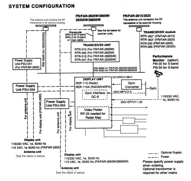
SYSTEM CONFIGURATION ............................................................................................... |
xii |
1. OPERATION
1.1 |
Turning on the Power ................................................................................................... |
1-1 |
1.2 |
Transmitter ON ............................................................................................................. |
1-1 |
1.3 |
Controls ........................................................................................................................ |
1-2 |
1.4 |
CRT Brilliance .............................................................................................................. |
1-6 |
1.5 |
Tuning the Receiver ...................................................................................................... |
1-6 |
1.6 |
On-screen Legends and Markers .................................................................................. |
1-7 |
1.7 |
Degaussing the CRT Screen ......................................................................................... |
1-8 |
1.8 |
Initializing the Gyro Readout ....................................................................................... |
1-9 |
1.9 |
Presentation Modes ....................................................................................................... |
1-9 |
1.10 |
Selecting the Range Scale ........................................................................................... |
1-12 |
1.11 |
Selecting the Pulsewidth ............................................................................................. |
1-12 |
1.12 |
Adjusting the Sensitivity ............................................................................................ |
1-14 |
1.13 |
Suppressing Sea Clutter .............................................................................................. |
1-14 |
1.14 |
Suppressing Precipitation Clutter ............................................................................... |
1-15 |
1.15 |
Interference Rejector .................................................................................................. |
1-15 |
1.16 |
Measuring the Range .................................................................................................. |
1-16 |
1.17 |
Measuring the Bearing ................................................................................................ |
1-16 |
1.18 |
Collision Assessment by Offset EBL ......................................................................... |
1-17 |
1.19 |
Measuring Range and Bearing Between Two Targets ................................................ |
1-18 |
1.20 |
Setting a Guard Zone (Guard Alarm) ......................................................................... |
1-18 |
1.21 |
Off-Centering .............................................................................................................. |
1-19 |
1.22 |
Echo Stretch ................................................................................................................ |
1-20 |
1.23 |
Echo Averaging........................................................................................................... |
1-21 |
1.24 |
Electronic Plotting Aid (EPA) .................................................................................... |
1-22 |
1.25 |
Target Trails (Echo Trails) .......................................................................................... |
1-24 |
1.26 |
Parallel Index Lines .................................................................................................... |
1-26 |
1.27 |
Anchor Watch ............................................................................................................. |
1-28 |
1.28 |
Origin Mark ................................................................................................................ |
1-29 |
1.29 |
Zoom ........................................................................................................................... |
1-30 |
1.30 |
Markers ....................................................................................................................... |
1-30 |
1.31 |
Menu Keys .................................................................................................................. |
1-31 |
1.32 |
RADAR 1 and 2 Menu Settings ................................................................................. |
1-32 |
1.33 |
Function Keys ............................................................................................................. |
1-33 |
1.34 |
EPA Menu ................................................................................................................... |
1-39 |
1.35 |
NAV INFORMATION Menu and Navigation Data Display ...................................... |
1-40 |
1.36 |
Radar Map .................................................................................................................. |
1-42 |
1.37 |
Suppressing Second-trace Echoes .............................................................................. |
1-43 |
1.38 |
Adjusting Relative Brilliance Levels of Screen Data ................................................. |
1-44 |
iii
1.39 |
Set and Drift (Set and Rate) ........................................................................................ |
1-44 |
1.40 |
Display of Ancillary Information ............................................................................... |
1-45 |
1.41 |
Alarms ........................................................................................................................ |
1-46 |
2. OPERATION OF ARPA
2.1 |
General ......................................................................................................................... |
2-1 |
2.2 |
Keys Used for ARPA .................................................................................................... |
2-1 |
2.3 |
ARPA Menu Operation ................................................................................................. |
2-2 |
2.4 |
Start-up Procedure ........................................................................................................ |
2-3 |
2.5 |
Automatic Acquisition .................................................................................................. |
2-4 |
2.6 |
Manual Acquisition....................................................................................................... |
2-7 |
2.7 |
Changing Plot Symbol Size .......................................................................................... |
2-7 |
2.8 |
Adjusting Brilliance of Plot Marks ............................................................................. |
2-10 |
2.9 |
Displaying Target Data ............................................................................................... |
2-10 |
2.10 |
Mode and Length of Vectors....................................................................................... |
2-11 |
2.11 |
Past Position Display .................................................................................................. |
2-11 |
2.12 |
Setting CPA/TCPA Alarm Ranges .............................................................................. |
2-12 |
2.13 |
Setting a Guard Zone .................................................................................................. |
2-13 |
2.14 |
Operational Warnings ................................................................................................. |
2-14 |
2.15 |
Trial Maneuver ........................................................................................................... |
2-15 |
2.16 |
ARPA Track Test ........................................................................................................ |
2-17 |
2.17 |
Criteria for Selecting Targets for Tracking ................................................................. |
2-18 |
2.18 |
Factors Affecting ARPA Functions ............................................................................. |
2-19 |
3. RADAR OBSERVATION
3.1 |
General ......................................................................................................................... |
3-1 |
3.2 |
False Echoes ................................................................................................................. |
3-2 |
3.3 |
SART (Search and Rescue Transponder) ..................................................................... |
3-3 |
3.4 |
RACON (Radar Beacon) .............................................................................................. |
3-5 |
4. MAINTENANCE
4.1 |
Periodic Maintenance Schedule .................................................................................... |
4-1 |
4.2 |
Life Expectancy of Major Parts .................................................................................... |
4-2 |
5. TROUBLESHOOTING
5.1 |
Easy Troubleshooting ................................................................................................... |
5-1 |
5.2 |
Advanced-level Troubleshooting .................................................................................. |
5-2 |
5.3 |
Diagnostic Test ............................................................................................................. |
5-5 |
APPENDIX
A.1 |
Performance Monitor ................................................................................................... |
A-1 |
A.2 |
For Fishing Vessel ....................................................................................................... |
A-2 |
A.3 |
Navigation Data (IEC 61162-1 Edition 1 and Edition 2) ............................................ |
A-3 |
A.4 |
Sentence Description ................................................................................................... |
A-7 |
MENU TREE ............................................................................... |
MN-1 |
|
Declaration of conformity to type |
|
|
Declaration of Conformity (FR/FAR-2855, FR/FAR-2855W, FR/FAR-2865SW)
iv

INTRODUCTION
A Word to the Owner of FURUNO Radar
Thank you for purchasing this FURUNO radar and/or ARPA. We are confident you will discover why FURUNO has become synonymous with quality and reliability.
Dedicated in the design and manufacture of marine electronics equipment for 50 years, FURUNO Electric Company has gained an unrivaled reputation as a world leader in the industry. This is the result of our technical excellence as well as our worldwide distribution and service network.
Please carefully read and follow the safety information and operating and maintenance instructions set forth in this manual before attempting to operate the equipment and conduct any maintenance. Your radar set will perform to the utmost of its ability only if it is operated and maintained in accordance with the correct procedures.
FR-2805 Series
The FR-2805 Series are available in the following two types:
Regular type and IMO type
The Regular type is for fishing boats and pleasure boats where some more functions are provided in addition to the functions of IMO type.
Note: You can easily recognize which type your radar/ARPA is by looking at the range scale provided.
The FURUNO FR-2805 Series of radars are designed to meet the exacting requirements of international and national standards and regulations including:
–IMO MSC-64 (67) Annex 4: Performance Standards for Radar Equipment –IMO A.477 (XII): Performance Standards for Radar Equipment
–A. 694 (17): General requirements for shipborne radio equipment forming part of the global
maritime distress and safety system (GMDSS) and for electronic navigation aids –IEC 60936-1: Shipborne Radar Operational and Performance Requirements –IEC 60936-2: Radar for HSC
–IEC 60945: Marine Navigational Equipment General Requirements
FAR-2805 Series ARPA
There are also Regular type and IMO type as in the FR-2805-I series radars. The IMO type ARPA complies with the following (Regular type also complies with but includes more additional functions convenient for practical uses in fishing):
–IMO Resolution A.823 (19): Performance standards for Automatic Radar Plotting Aids –A. 694 (17): General requirements for shipborne radio equipment forming part of the global maritime distress and safety system (GMDSS) and for electronic navigation aids –Results of NAV 40/WP.3/Add. l which is to be met for new building on or after January 1, 1997
–IEC 60945:1996-11: Marine Navigational Equipment General Requirements
–Us Navigation safety regulations, Labeling requirement in § 164.38(d)(1) of CFR33
v

"This device was designed and manufactured to comply with the International Maritime Organization (IMO) Performance Standards for Automatic Radar Plotting Aids (ARPA)."
WARNING
If your ship is 10,000 or more gross tons and scheduled to operate in the navigable waters of the United States, make sure the above label is attached on the ARPA. Otherwise please make one yourself by typing and gluing overleaf with the transparent seal.
Precautions on high speed craft
Assume your ship is making 40 kt and a target ship is approaching at 40 kt right toward you. Then the relative speed is 80 kt. With the antenna revolving at 42 rpm, the target blip appears jumping to a new location 59 m nearer. This jump corresponds to 23 mm on the 360 mm display using the 0.25 nm range scale. On such a short range you may lose the track of target in the midst of sea clutter, random noise or other targets. Use one step larger range scale.
ARPA can fail to track a target when the relative speed exceeds 100 kt.
About This Manual
This manual is designed to provide information on operation and maintenance of the FR-2805 series radars as well as fault diagnosis and troubleshooting procedures which may be performed by suitably qualified personnel on board.
In producing this manual, we tried to provide as "user friendly" an operation guide as possible to the many functions of this sophisticated equipment. We would appreciated feedback from you about this manual. Your comments and suggestions would be valuable inputs for future improvement.
Categorization by specification
See the table on the next page.
vi
Item |
IMO-type |
R-type |
|
|
|
Range Scales |
0.125, 0.25, 0.5, 0.75, 1.5, |
FR-2805 and FAR-2805 |
|
3, 6, 12, 16, 24, 48, 96 nm |
0.125, 0.25. 0.5, 0.75, 1.5, 3, 6, |
|
|
12, 24, 48, 72nm |
|
|
Other models: |
|
|
0.125, 0.25, 0.5, 0.75, 1.5, 3, 6, |
|
|
12, 16, 24, 32, 48, (72) 120 nm |
|
|
|
Guard Zone |
IRange depth fixed to 0.5 |
Inward (CZ) or outward (Anchor) |
|
nm with both outer and |
guard alarm selectable. |
|
inner limits settable |
|
|
between 3 and 6 nm. |
Outer and inner limits can be set |
|
|
at any distance from own ship. |
|
|
ARPA guard ring: |
|
|
Outer limit: 0.7-32 nm |
|
|
Width of ring: 0.5 nm |
|
|
Sector angle: 1-360° |
|
|
|
Off-centering |
Up to 75% of range in use |
Up to 100% of range in use in |
|
in any direction |
any direction |
|
|
|
Anchor Watch |
Available in stand-by only |
Available in either stand-by or |
|
|
transmit status |
|
|
|
Own Ship Mark |
Standard mark |
Displayed when Anchor Watch is |
|
|
activated. (Entry of ship data |
|
|
required.) |
|
|
|
x2 Zoom |
No |
Yes |
|
|
|
Stern Marker |
No |
Yes |
|
|
|
Features
The new FR-2805 series of radar and the FAR-2805 series of ARPAs are the results of combination of the FURUNO's many years of experience in the marine field and the advanced computer technology. The FR-2805 series and FAR-2805 series are designed to fully meet the exacting rules of the International Maritime Organization (IMO) for installations on all classes of vessels.
The display unit employs a 28" diagonal high-resolution green-phosphor CRT. It provides an effective radar picture of 360 mm diameter leaving sufficient space for on-screen alphanumeric data.
Target detection is enhanced by the sophisticated signal processing technique such as multilevel quantization (MLQ), echo stretch, echo average, and a built-in radar interference rejector. Audible and visual guard zone alarms are provided as standard. Other ship's movement is assessed by trails of target echoes or by electronic plotting. The FAR-2805 series ARPA further provides target assessment by historical plots, vectors and target data table.
On-screen data readouts include CPA, TCPA, range, bearing, speed/course of own ship and up to 3 targets. The ARPA functions include automatic acquisition of up to 20 targets, or manual acquisition of 40 targets. In addition, the ARPA features display of a traffic lane, buoys, dangerous points, and other important reference points.
vii
General features
Daylight-bright high-resolution display
28" diagonal CRT presents radar picture of 360 mm effective diameter with alphanumeric data area around it
User friendly operation by combination of tactile backlit touchpads, a trackball and rotary controls
Audio-visual alert for targets in guard zone
Echo trail to assess targets' speed and course by simulated afterglow
Electronic plotting of up to 10 targets in different symbols (This function is disabled when ARPA is activated.)
Electronic parallel index lines
Interswitch (optional) built in radar or ARPA display unit
Enhanced visual target detection by Echo Average, Echo Stretch, Interference Rejector, and multi-level quantization
Stylish display
Choice of 10, 25 or 50 kW output for X-band; 30 kW output for S-band, either in the transceiver aloft (gearbox) or RF down (transceiver in bridge)
Exclusive FURUNO MIC low noise receiver
ARPA features
Acquires up to 20 targets automatically plus up to 20 targets manually, or all 40 targets manually
Movement of tracked targets shown by true or relative vectors. (Vector length 1 to 99 min. selected in 1 min. steps.)
Setting of nav lines, buoy marks and other symbols to enhance navigation safety
On-screen digital readouts of range, bearing, course, speed, CPA (Closest Point of Approach), TCPA (Time to CPA), BCR (Bow Crossing Range) and BCT (Bow Crossing Time) of 2 targets out of all tracked targets.
Audible and visual alarms against threatening targets coming into operator-selected CPA/ TCPA limits, lost targets, targets, two guard rings, visual alarm against system failure and target full situation
viii
Specifications
ANTENNA RADIATORS
1. Type
Slotted waveguide array
2. Beamwidth and sidelobe attenuation
Band |
|
|
|
X-band |
|
|
S-band |
||
|
|
|
|
|
|
|
|
|
|
Radiator |
|
XN12AF |
XN3 |
XN20AF |
XN24AF |
XN5A |
SN36AF |
SN30AF |
|
type |
|
|
|
(XN3A) |
(XN4A) |
|
|
|
|
Beamwidth |
1.8° |
1.23° |
1.23° |
0.95° |
0.75° |
2.1° |
2.5° |
||
(Hor.) |
|
||||||||
|
|
|
|
|
|
|
|
||
Beamwidth |
20° |
25° |
20° |
20° |
20° |
25° |
25° |
||
(Ver.) |
|
||||||||
|
|
|
|
|
|
|
|
||
Sidelobe att |
28 dB |
24 dB |
28 dB |
28 db |
26 db |
25 dB |
24 db |
||
within ± 10° |
|||||||||
|
|
|
|
|
|
|
|||
Sidelobe att |
32 dB |
30 dB |
32 dB |
32 dB |
30 db |
30 dB |
30 db |
||
outside ± |
10° |
||||||||
|
|
|
|
|
|
|
|||
* 10 ft radiator SN30AF available for NON-SOLAS ship. (FAR-2835S HSC is available for SOLAS ship.)
3.Polarization
Horizontal
4.Rotation
FR/FAR-2815/2825: 24/42 rpm FR/FAR-2825W2855W, FR/FAR-2835SW/2865SW: 21 rpm (50 Hz),
26 rpm (60 Hz) FR/FAR-2835S: 21 rpm (50 Hz),
26 rpm (60 Hz),
45 rpm (for HSC) FR/FAR-2855: 16 rpm (50 Hz),
20 rpm (60 Hz or DC)
RF TRANSCEIVER
1. Frequency
X-band: 9410 MHz ± 30 MHz
9415 MHz ± 30 MHz(50kW)
S-band: 3050 MHz ± 30 MHz
2. Output power
FR/FAR-2815: |
12 kW |
FR/FAR-2825/2825W: |
25 kW |
FR/FAR-2855-I/2855W: |
50 kW |
FR/FAR-2835S-I/2835SW: |
30 kW |
FR/FAR-2865SW: |
60 kW |
3. Pulselength/PRF
FR/FAR-2815/2825
Range(nm) |
Pulselength ( s) |
PRR (Hz) |
0.125, 0.25 |
0.07 |
2200 |
0.5, 0.75 |
0.07/0.15 |
2200 |
1.5Two from 0.07, 0.15, 0.3 2200/1000
3 |
Two from 0.15, 0.3, 0.5 |
2200/1000 |
6 |
Two from 0.3, 0.5, 1.2 |
1000/600 |
12, 24 |
Two from 0.5, 1.2 |
1000/600 |
48, 96 |
1.2 |
600 (48 |
|
|
nm)/500 |
|
|
(96 nm) |
FR/FAR-2825W, 2855, 2855W, 2835S, 2835SW, 2865SW:
Range (nm) |
|
Pulselength ( s) |
PRR (Hz) |
0.125, 0.25, 0.5 |
0.08 |
2200 |
|
0.75, 1.5 |
|
0.08/0.3* |
2200 |
3 |
Two from 0.08, 0.3*, 0.6 2200/1100 |
||
6 |
Two from 0.08, 0.3*, 0.6 2200/1100 |
||
12, 24 |
0.6, 1.2 |
1000/600 |
|
48, 96 |
1.2 |
|
600/500 |
*: In case of FR-2855, FR-2855W, FR-2865SW
0.3is replaced with 0.2.0
4.I.F.
60 MHz, Logarithmic
S1-M1: 28 MHz
M2-Lpulse: 3 MHz
5. Duplexer
Ferrite circulator with diode limiter for FR/FAR-2815/2825/2835S/2835sw Ferrite circulator with TR limiter for FR2825W/2855/2855W/2865SW
6. Noise figure
FR/FAR-2815/2825/2825W/2855/2855W/ 2835S: 6 dB
FR/FAR-2835SW: 4 dB FR/FAR-2865SW: 4.5 dB
RADAR DISPLAY
1. Picture tube
28" color CRT, Effective radar diameter 360 mm
IMO type: Yellow or green echoes in 16 levels R-type: Yellow or green echoes in 16 levels or
3 colors depending on echo strengths Different color for VRM, range rings, alarms, etc.
Raster scan at 32.25 kHz horizontal, 60 Hz vertical. Number of scanning lines 1024, interlaced.
2.Minimum range and discription
35 m
3.Range scales (nm)
IMO type:
0.125 (.025), 0.25 (0.05), 0.5 (0.1), 0.75 (0.25), 1.5 (0.25), 3 (0.5), 6 (1), 12 (2), 24 (4), 48 (8), 96 (16)
R-type:
0.125 (.025), 0.25 (0.05), 0.5 (0.1), 0.75 (0.25), 1.5 (0.25), 3 (0.5), 6 (1), 12 (2), 16 (4), 24 (4), 32 (8), 48 (8), 72 (16), 120 (20)
4. Range accuracy
1% of range in use or 15 m whichever is the greater
ix
5.Bearing accuracy
±1°
6.Bearing discrimination
Better than 2.5° except S-band 10 ft radiators (SN-30AF)
7. Presentation modes
Head-up, Head-up TB, North-up, Course-up, True motion north-up
(Automatically set to HU in case of compass failure)
8. Variable Range Markers
Two Variable Range Markers, switched
9. Electronic Bearing Lines
Two Electronic Bearing Lines, switched Range merker on EBL
10.Offcenter
IMO type: Sweep origin can be offcentered by 75% of range in use in any direction. Regular type: Any direction up to 100%
11.Target alarm zone
2 TAZ at 3 and 6 nm in width of 0.5 nm, any sector.
12.Electronic plotting (E-plot)
10 targets manual plotting. Not operative in ARPA mode.
13.Parallel index lines
2, 3 and 6 lines (selectable on menu)
14.Navigation lines (option)
Two lines to define a navigation channel (with RP-25)
ARPA FUNCTIONS
1. Acquisition
Instant selection of auto or manual acquisition in 0.2 to 32 nm, relative speed 100 kt. Auto 20 targets plus manual 20 targets, or Manual
40targets
2.Tracking
Automatic tracking of all acquired targets on the display for 5 out of 10 consecutive scans in 0.1 to 32 nm
3. Prediction of target motion
True or relative vectors, time scaled.
Length: 1 to 99 min
4. Past positions
5 or 10 past positions of tracked targets at intervals of 2 min
5. Collision warning
CPA limit: 0.2 to 10 nm TCPA limit: 0 to 99 min
6. Guard zone (Guard ring)
2 guard zones (guard rings) of operatordefined width in 0.7 to 32 nm, Sector 1 to 360° any direction
7. Trial maneuver
Simulates the effect on all tracked targets of own ship maneuver with course, speed and delay time.
INTERFACING
1. IEC 61162-1
OSD, RSD, TTM, etc. (Listener 2 mA at 2V, Talker 60 mA max)
2. Analog
RGB video, H/V sync for VDR with optional board)
3.Gyrocompass
Built-in interface accepts synchro signal (2050 V, 50-400 Hz) or stepper signal (20-50 VDC, any polarity).
4. Speed log (IEC 61192-1 interface)
IEC 61192-1 contact closure or 200/400/500 pulses/nm.
POWER SUPPLY
1. FR/FAR-2815/2825
115/230 VAC, 1ø, 470 VA(2815), 500 VA(2825), DC set not available
2. FR/FAR-2825W/2855/2855W
Display unit: 115/230 VAC, 1ø, 500 VA (2825W), 115 VAC, 1ø, 550 VA (2855/ 2855W)
Antenna unit: 115/230 VAC, 1ø, 150 VA (2825W/2855W), 230 VAC, 3ø, 120 VA, 380/ 440 VAC, 3ø, 120 VA (2825W/2855W), 24 V, 30 W (2855)
3. FR/FAR-2835S/2835SW
Display unit: 115/230 VAC, 1ø, 500 W Antenna unit: 220 VAC, 50-60 Hz, 3ø,
440VA, 380/440 VAC, 50-60 Hz, 3ø, 440 VA
4.FR/FAR-2865SW
Display unit: 115 VAC, 1ø, 550 VA Antenna unit: 220 VAC, 3ø, 50-60 Hz, 440 VA, 380/440 VAC, 3ø, 50-60 Hz, 440 VA
x
PROGRAM NUMBER
SPU Board
MAIN: 0359096132
SUB: 0359057134
ARP Board
ARP: 1859038106
SUB: 18590399101
RP Board
0359094111
EQUIPMENT LIST
Standard Supplies
1.Display unit
Radar: RDP-115 (w/RP-25)
ARPA: RDP-115A (w/ARP-25, RP-25)
2.Antenna unit with 30 m antenna cable
3.RF transceiver unit for RF-down system
4.PSU-004 for FR/FAR-2825W/2855W/ 2835S/2835SW/2865SW
5.PSU-001 for FR/FAR-2855
6.Standard spare parts and installation materials
Optional Supplies
1.Waveguide for RF-down system (Coax cable for S-band)
2.Gyro interface GC-8
3.Interswitch box RJ-7 or 8
4.Performance monitor PM-30* (X-band), PM-50* (S-band)
5.42 rpm scanner motor
(FR/FAR-2815/2825 only)
6.45 rpm scanner motor for HSC (FAR-2835S only)
7.Video plotter RP-25**
8.ARPA Board ARP-25
9.Hand grip
10.Display pedestal
11.Interface unit IF-2300*
*Necessary in IMO-type Radar and ARPA
**RP-25 (Radar Video Picture) necessary for all class of SOLAS ships for radar maps and navlines
***ARP-25 (Auto Radar Plotter) may not be necessary on ships below 1,000 GT. Check with the Administrations.
Category of Equipment Units
Equipment for Protected Area •Display unit
•Power supply unit •RF transceiver unit •Interswitch unit
Equipment for Exposed •Antenna unit •Performance monitor
Compass safe distance
See each corresponded Installation Manual.
xi
FR/FAR-2855/2835S ANTENNA UNIT
RW-4873 (for 2815/2825)
RW-6895
CO-SPEVV-SB-C
2C 1.5 m Interface
IF-2300
Interswitch
RJ-7.8
115/230 VAC, 1φ , 50/60 Hz
(Ant and disp for FR/FAR2815/2825)
 Radar system data and target data in
IEC61162 chart data, etc. NAV data (GLL ..)
Speed (VBW, VHW)
TRUE Heading (HDT)
Other Radar system
External Buzzer
xii
ANTENNA UNIT (Turning unit or Gearbox)
Model |
Antenna unit |
Motor type |
|
|
|
|
|
FR/FAR-2815 |
RSB-0074 (24 rpm, 24 VDC)* |
D8G-516 |
|
|
|
||
RSB-0075 (42 rpm, 24 VDC)* |
D8G-571 |
||
|
|||
|
|
|
|
FR/FAR-2825 |
RSB-0074 (24 rpm, 24 VDC)* |
D8G-516 |
|
|
|
||
RSB-0075 (42 rpm, 24 VDC)* |
D8G-571 |
||
|
|||
|
|
|
|
|
RSB-0049 (16 rpm (50 Hz)/20 rpm (60 Hz), |
GOB-8222 |
|
FR/FAR-2855 |
200/220 VAC, 3φ ) |
||
|
|||
|
RSB-0050 (20 rpm, 24 VDC) |
RM-6585 |
|
|
|
|
|
|
RSB-0076 (21 rpm (50 Hz)/26 rpm (60 Hz), |
RM-8123 |
|
|
200/220 VAC, 3φ ) * |
||
|
|
||
|
|
|
|
FR/FAR-2825W |
RSB-0077 (21 rpm (50 Hz)26 rpm (60 Hz), |
RM-8124 |
|
FR/FAR-2855W |
380/440 VAC, 3φ ) * |
||
|
|||
|
|
|
|
|
RSB-0078 (21 rpm (50 Hz)26 rpm (60 Hz), |
RM-8247 |
|
|
380/440 VAC, 1φ ) * |
||
|
|
||
|
|
|
|
|
RSB-0026 (21 rpm (50 Hz)26 rpm (60 Hz), |
RM-7398 |
|
|
200/220 VAC, 3φ ) |
||
|
|
||
|
|
|
|
|
RSB-0031 (21 rpm (50 Hz)26 rpm (60 Hz), |
RM-7435 |
|
|
200/220 VAC, 3φ ) |
||
|
|
||
|
|
|
|
FR/FAR-2835S |
RSB-0088 (45 rpm, 220 VAC, 3φ , 50 Hz) for |
RM-9519 |
|
HSC S-band |
|||
|
|
||
|
|
|
|
|
RSB-0089 (45 rpm, 220 VAC, 3φ , 60 Hz) |
RM-9520 |
|
|
HSC S-band |
||
|
|
||
|
|
|
|
|
RSB-0090 (45 rpm, 440 VAC, 3φ , 60 Hz) |
RM-9521 |
|
|
HSC S-band |
||
|
|
||
|
|
|
|
|
RSB-0027 (21 rpm (50 Hz)26 rpm (60 Hz), |
RM-7398 |
|
|
200/220 VAC, 3φ ) |
||
FR/FAR-2835SW |
|
||
|
|
||
RSB-0032 (21 rpm (50 Hz)26 rpm (60 Hz), |
RM-7435 |
||
|
|||
|
380/440 VAC, 3φ ) |
||
|
|
||
|
|
|
NOTE: The gearboxes marked * work with new radiators (such as XN12AF *). The new radiator has different physical dimensions at the rotary joint and only fits on the new gear box. The slotted waveguide array radiators are the same as the current ones. The gearing and motors are the same as those in the former counterpart. Assembled antenna are compatible to each other within the same for RF output.
RADIATOR
4 ft |
Type XN-12AF* |
8 ft |
Type XN-4A, 24AF* |
X-Band |
|
|
|
|
|
||
6.5 ft |
Type XN-3, 3A, 20AF* |
10 ft |
Type XN-5A |
||
|
|||||
|
|
|
|
|
|
12 ft |
SN-36AF |
10 ft |
SN-30AF |
S-Band |
|
|
|
|
|
|
|
NOTE: Radiators marked * for RSB-0074/0075/0076/0077/0078 |
|
||||
|
|
|
|
|
|
xiii
1. OPERATION
 WARNING
Before turning on the radar, make sure that there is no one near the antenna unit. Serious injury or even death may result if a rotating antenna strikes someone standing nearby.
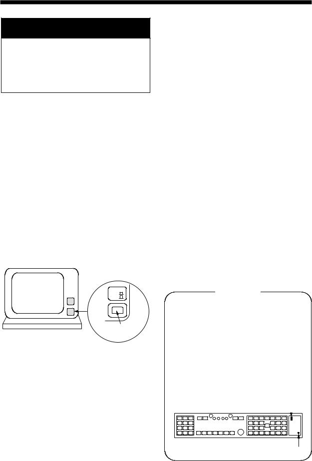
1.1 Turning on the Power
The POWER switch is located at the lower right corner of the display. Push it to switch on the radar set. To turn off the radar, push it again; the switch will extend. The screen shows the bearing scale and digital timer approximately 15 seconds after power-on. The timer counts down three minutes of warm-up time. During this period the magnetron, or the transmitter tube, is warmed for transmission. When the timer has reached 0:00, the legend STBY appears indicating that the radar is now ready to transmit pulses.
POWER
ON
OFF
Power switch
Location of power switch
In warm-up and standby condition, you will see the message BRG SIG MISSING. This is normal because a bearing signal is not yet generated when the antenna is not rotating. ON TIME and TX TIME values shown at the bottom of the screen are the time counts in hours and tenths of hour when the radar has been powered on and transmitted.
1.2 Transmitter ON
When the STANDBY status is displayed on the screen, press the Transmit switch labeled ST-BY/TX on the control panel of the display unit.
The radar is initially set to previously used range and pulsewidth. Other settings such as brilliance levels, VRMs, EBLs and menu option selections are also set to previous settings.
The Transmit switch toggles the radar between STANDBY and TRANSMIT status. The antenna stops in STANDBY status and rotates in TRANSMIT status.
Notes:
1)If the antenna does not rotate in TRANSMIT status, check whether the antenna switch in the tuning compartment is in the OFF position.
2)The magnetron ages with time resulting in a reduction of output power. It is highly recommended that the radar be set to STANDBY status when not used for an extended period of time.
Quick Start
Provided that the radar was once in use with the transmitter tube (magnetron) still warm, you can turn the radar into TRANSMIT condition without 3-minutes standby. If the Power Switch has been turned off by mistake or the like and you wish to restart the radar promptly, follow the steps below:
•Turn on the Power Switch not later than 5 sec after power-off.
•Press the ST-BY switch in the tuning compartment.
•Press the Transmit Switch STBY/TX.
Antenna switch 
ORIGIN |
VECTOR |
MARK |
TIME |
ST-BY switch
1-1
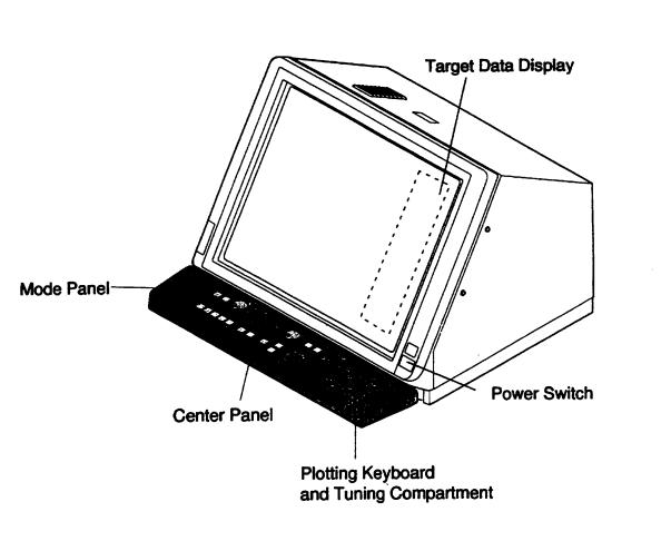
1.3 Controls
FR-2805 Series Radar Display Unit Overview
1-2
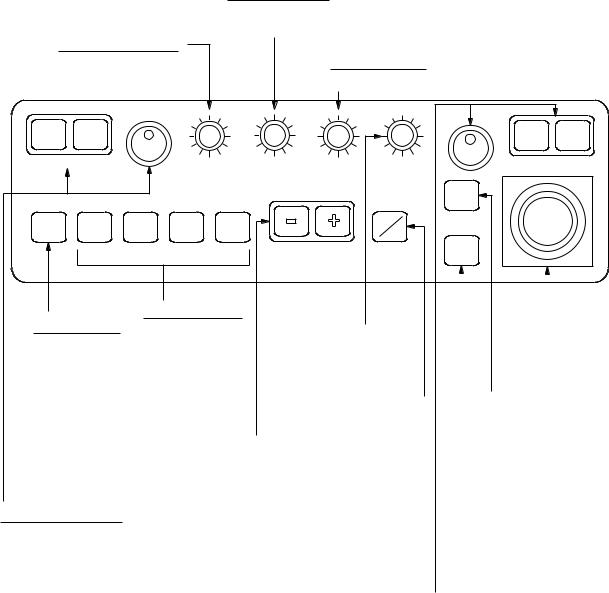
Main control panel
BRILLIANCE control Adjusts brightness of entire screen.
A/C RAIN control Reduces clutter from rain, snow and clouds.
A/C SEA control
Reduces sea clutter.
OFF |
ON |
|
|
EBL |
|
BRILL |
|
A/C |
FUNC1 |
FUNC2 FUNC3 FUNC4 |
|
AUTO |
|||
|
|
A/C AUTO key Reduces sea clutter at preset level. Permits manual override by A/C SEA and A/C RAIN controls.
FUNCTION keys #1 key: Setup 1 #2 key: Setup 2 #3 key: Setup 3 #4 key: Setup 4
EBL ON/OFF control Pressing ON key toggles between No.1 EBL and No.2 EBL. Bearing is read either Relative or True at the lower left corner of the screen.
|
|
OFF |
ON |
A/C RAIN |
A/C SEA |
GAIN |
VRM |
|
|
ACQ |
|
|
|
ST-BY |
|
|
|
TX |
|
|
RANGE |
AUDIO |
|
|
OFF |
|
|
|
|
|
|
|
|
|
|
|
|
|
|
|
|
|
|
|
|
|
|
GAIN control |
|
|
|
Trackball |
|
|||||||||||
|
|
|
Shifts cursor |
|||||||||||||
|
|
|
|
|
|
|
|
|
|
|||||||
Adjusts receiver |
||||||||||||||||
|
|
|
on radar |
|||||||||||||
sensitivity. |
|
|
|
|
|
|
|
|||||||||
|
|
|
|
|
|
|
screen. |
|||||||||
|
|
|
|
|
|
|
|
|
|
|||||||
TRANSMIT switch |
|
|
|
|
ACQ key |
|
||||||||||
|
|
|
||||||||||||||
|
|
|
|
|
|
|
|
|
||||||||
|
|
|
|
|
|
|
|
|
Press key after |
|||||||
RANGE keys |
|
|
|
|
|
|
|
selecting target by |
||||||||
|
|
|
|
|
|
|
trackball. The target |
|||||||||
Selects range |
|
|
|
|
||||||||||||
|
|
|
|
|
|
will be acquired in |
||||||||||
scales. |
|
|
|
|
|
|
30 sec. |
|||||||||
|
|
|
|
|
|
|
|
|
|
|
|
|
|
|
||
|
|
|
|
|
|
|
AUDIO OFF key |
|
||||||||
|
|
|
|
|
|
|
Silences aural alarm |
|||||||||
|
|
|
|
|
|
|
(except guard alarm) |
|||||||||
|
|
|
|
|
|
|
and ARP-23 (option) |
|||||||||
|
|
|
|
|
|
|
generated alarm. |
|||||||||
|
|
|
VRM ON/OFF keys and rotary control |
|||||||||||||
|
|
|
Press ON to activate VRM. Turn |
|
||||||||||||
|
|
|
rotary control clockwise to increase |
|||||||||||||
|
|
|
VRM diameter; counterclockwise to |
|||||||||||||
|
|
|
decrease it. Read range at lower-right |
|||||||||||||
|
|
|
hand corner of screen. There are two |
|||||||||||||
|
|
|
VRMs which are toggled by each press |
|||||||||||||
|
|
|
of ON key. Press OFF key to deactivate |
|||||||||||||
|
|
|
each VRM. |
|
|
|
|
|
|
|
|
|
||||
GAIN, A/C RAIN, A/C SEA and BRILL controls are of push-and-rotate type. Push in wanted switch lightly, and it will pop up. Rotate it to the wanted setting and push it in. The retracted position of the controls provides a better protection for water splash.
1-3
Display controls
Mode Panel
HM |
ECHO |
MODE |
|
OFF |
TRAILS |
||
|
|||
GUARDORIGIN |
VECTOR |
VECTOROFF |
|
EBL |
|||
ALMARKM |
TRUE/ |
CENTTIMER |
|
OFFSETREL |
|||
X2 |
BKGR |
INDEX |
|
ZOOM |
COLOR |
LINES |
|
CU, TM |
INT |
RINGS |
|
RESET |
REJECT |
||
|
HM OFF
Temporarily erases the heading marker.
ECHO TRAILS
Shows trails of target echoes in the form of simulated afterglow.
MODE
Selects presentation modes: Head-up, Head-up/TB, North-up, Course-up and True Motion.
GUARD ALARM
Used for setting the guard alarm.
EBL OFFSET
Activates and deactivates off-centering of the sweep origin.
BKGR COLOR
Selects the background color.
INDEX LINES
Alternately shows and erases parallel index lines.
X2 ZOOM
Enlarges a user-selected portion of picture twice as large as normal. (R-type only)
CU, TM RESET
Resets the heading marker to 000° in course-up mode; moves own ship position to 50% radius in stern direction in the true motion mode.
INT REJECT
Reduces mutual radar interference.
RINGS
Adjusts the brightness of range rings.
1-4

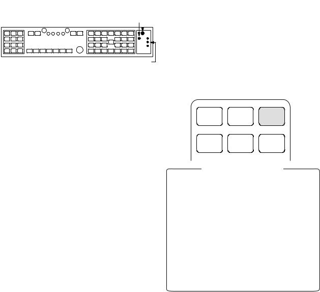
Plotting keypad and tuning compartment
Keys for ARPA (FAR)
ORIGIN |
VECTOR |
VECTOR |
RADAR |
|
|
|
MARK |
TRUE/ |
TIME |
MENU |
|
|
|
REL |
1 |
2 |
3 |
|||
|
|
|
|
|||
TARORIGETIN |
VECTORTARGET |
VECAUTOR |
|
|
|
|
MDATARK |
BASEDTRUE/ |
PLOTTIME |
|
|
|
|
DATAREL |
E,AUTO |
4 |
5 |
6 |
||
|
|
|
||||
|
|
|
|
|
|
|
|
|
|
PLOT |
|
|
|
|
LOST |
|
MENU |
|
|
|
TRIAL |
HISTORY |
|
|
|
|
|
TARGET |
|
|
|
|
||
|
|
|
7 |
8 |
9 |
|
|
|
|
|
|||
MARK |
CHART |
VIDEO |
NAV |
CANCEL |
|
ENTER |
ALIGN |
PLOT |
MENU |
– |
|
||
|
9 |
|
||||
|
|
|
|
|
Keys for RP-25 (option)
AUTO |
TUNE |
|
AUTO |
GYRO SET |
|
MANU |
||
|
||
|
HOLD |
|
ON |
|
|
ANTENNA |
+ |
|
|
||
OFF |
– |
|
|
||
DEGAUSS |
ERROR |
STBY
PM-ON/OFF
ORIGIN MARK
Show and erases the origin mark (a reference point for range/bearing measurement).
VECTOR TRUE/REL
Selects true or relative vector.
VECTOR TIME
Sets vector length in time.
RADAR MENU
Opens and closes RADAR menus.
E-PLOT, AUTO PLOT MENU
Opens and closes E-Plot and optional AUTO PLOT menus.
NAV MENU
Opens and closes NAV menu.
Keys 0-9
Select plot symbols. Also used for entering numeric data.
CANCEL
Terminates plotting of a specified target or all tracked targets.
ENTER
Used to save settings on menu screen.
Keys for ARPA (optional in R-type)
TARGET DATA
Displays the acquired target data.
TARGET BASED DATA
Own ship's speed is measured relative to a fixed target.
AUTO PLOT
Activates and deactivates the Auto Plotter.
TRIAL
Initiates a trial maneuver.
LOST TARGET
Silences the lost target audible alarm and erases the lost target symbol.
HISTORY
Shows and erases past positions of tracked targets.
Keys for Video Plotter (optional)
MARK Enter/erase marks
CHART ALIGN
Used to align chart data.
VIDEO PLOT
Turns the video plotter on/off.
1-5
1.4 CRT Brilliance
Operate the BRILL control on the control panel of the display unit to adjust the entire screen brightness. Note that the optimum point of adjustment varies with ambient light conditions, especially between daytime and nighttime.
Brilliance control
BRILL |
A/C RAIN |
A/C SEA |
GAIN |
|
|
|
|
Note: The CRT brilliance should be adjusted before adjusting relative brilliance levels on the BRILLIANCE menu to be explained later.
1.5 Tuning the Receiver
Auto tune
The radar receiver is tuned automatically each time the power is turned on, thus there is no front panel control for tuning purpose. The tuning indicator and the label AUTO TUNE at the top right corner of the display unit show the tuning circuit is working. If the label AUTO TUNE is not displayed, check that the TUNE selector in tuning compartment is in the AUTO position.
Manual tune
If you are not satisfied with the current auto tune setting, follow these steps to fine-tune the receiver:
1.Set the TUNE selector in the tuning compartment to MAN for manual tuning.
TUNE control
TUNE selector
|
|
|
|
|
|
|
|
|
|
|
|
ORIGIN |
|
VECTOR |
|
VECTOR |
|
|
REL |
|
|
||
MARK |
|
TRUE/ |
|
TIME |
|
|
|
|
|
2.Push the tune control so that it pops up.
3.While observing the picture on the 48 mile scale, slowly adjust TUNE control and find the best tuning point.
4.So the TUNE selector to AUTO and wait for about 10 seconds or four scanner rotations.
5.Make sure that the radar has been set to the best tuning point. This condition is where the tuning indicator lights to about 80% of its total length.
6.Push the TUNE control into the retracted position.
Video Lockup Recovery
Video lockup, or picture freeze, can occur unexpectedly on digital rasterscan radars. This is mainly caused by heavy spike noise in the power line and can be noticed by carefully watching the nearly invisible sweep line. If you suspect that the picture is not updated every scan of the antenna or no key entry is accepted notwithstanding the apparently normal picture, do Quick Start to restore normal operation:
1.Turn of the power switch and turn it on again within five seconds.
2.Push the ST-BY switch in the tuning compartment.
3.Push the Transmit switch labeled ST-BY/TX for Transmit status.
This LED lights if video lockup is associated with fundamental malfunction of CPU.
ST-BY switch for quick start
1-6
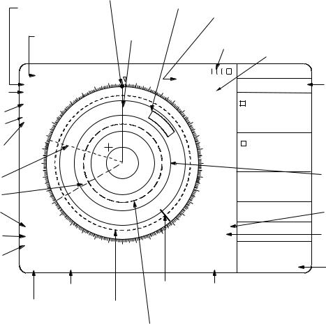
1.6 On-screen Legends and Markers
|
|
|
|
Heading |
|
|
|
|
|
|
mark |
|
|
|
Range and bearing of |
|
|
|
||
|
cursor from own ship |
|
Heading |
|||
|
|
|
|
|
||
|
Range ring |
|
line |
|
||
|
|
|
|
|||
|
interval/Range |
|
|
|
||
|
6/1 |
NM |
340 |
350 000 |
010 |
020 |
|
1.5 NM |
|
|
|
||
Presentation |
330.0° T |
|
330 |
|
|
|
HEAD UP |
320 |
|
|
|
|
|
mode |
RM |
|
|
|
|
|
|
|
|
|
|
||
Pulselength |
PULSE 1 310 |
|
|
|
|
|
IR3 |
|
|
|
|
|
|
Interference |
ES1 300 |
|
|
|
|
|
rejector |
290 |
|
|
|
|
|
Echo stretch |
280 |
|
|
|
|
|
|
270 |
|
|
|
|
|
Guard zone
Antenna/Radar in use
Tuning indicator
|
|
|
Alarm clock |
|
|
|
AUTO TUNE |
GYRO |
132.7° |
|
|
|
LOG |
2.2KT |
|
||
|
ANT 1 MAIN |
ARPA |
|
Target data |
|
030 |
|
|
|||
WATCH |
REL VECTOR 6MIN |
||||
|
display |
||||
|
040 11:30 |
RNG 4.91NM |
|||
|
1997 |
|
|||
|
1 BRG 226.1° T |
(See next |
|||
|
050 02/08 |
||||
|
13:28* |
TRU CSE 263.3° T |
page.) |
||
|
060 |
TRU SPD |
12.4KT |
||
|
CPA 2.9NM TCPA *** MIN |
|
|||
|
|
|
|||
|
070 |
BCR 8.9NM BCT 20MIN |
|
||
|
RNG 4.91NM |
|
|||
|
|
|
|||
|
080 |
2 BRG 226.1° T |
|
||
|
TRUCSE 263.3° T |
|
|||
|
|
|
|||
|
090 |
TRU SPD |
12.4KT |
|
|
|
CPA 2.9NM TCPA *** MIN |
|
|||
|
|
BCR 8.9NM BCT 20MIN |
|
||
No.1 EBL
No.2 EBL
260 |
100 |
250 |
110 |
|
CURRENT *.*KT *.*° T WIND *.*KT *.*° R
Fixed range ring
Automatic |
240 |
|
|
|
120 |
|
|
|
|
|
|
||
|
|
|
|
|
|
|
clutter |
230 |
|
|
|
130 |
|
|
A/C |
|
|
|
TGT ALARM |
OS |
|
AUTO |
220 |
|
140 |
||
Noise |
|
[GPS] |
||||
NOISE |
210 |
|
150 |
TRU TRAIL |
||
rejector |
REJ |
|
30MIN |
+ |
||
OFFCENTER |
200 190 180 170 |
160 |
15:26 |
GYRO LOG EPSF |
||
Off-center |
EBL |
|
|
|
VRM |
AZIMUTH HDG TRIG |
|
|
|
VIDEO LOST TARGET |
|||
|
>287.2° T< |
PI |
|
|
>5.65NM< |
AUTO MAN TGT FULL |
|
239.6° T |
348.6° T |
|
|
2.35NM |
GZ COLLOSION SOG |
|
Parallel Index Line |
North marker No.1 VRM (upper) |
||||
|
No.1 EBL (upper) |
No.1 VRM |
|
No.2 VRM (lower) |
||
|
|
|
|
|||
|
No.2 EBL (lower) |
|
|
|
||
|
|
|
|
|
||
No.2 VRM
Target alarm ON
Echo trail settings
Error Message appears in red.
1-7

1.7Degaussing the CRT Screen
Each time the radar is turned on, the degaussing circuit automatically demagnetizes the CRT screen to eliminate color contamination caused by earth's magnetism or magnetized ship structure.
The screen is also degaussed automatically when own ship has made a significant course change. While being
degaussed, the screen may be disturbed momentarily with vertical lines. If you wish to degauss by manual operation at an arbitrary time, open and press the "DEGAUSS" switch.
Gyro
LED
DEGAUSS switch

ORIGIN |
|
VECTOR |
|
VECTOR |
|
REL |
|
||
MARK |
|
TRUE/ |
|
TIME |
|
|
|
||
|
|
|
|
|
Gyro readout adjustment switches
1-8
1.8Initializing the Gyro Readout
Provided that your radar is interfaced with a gyrocompass, ship's heading is displayed at the top of the screen. Upon turning on the radar, align the on-screen GYRO readout with the gyrocompass reading by the procedure shown below. Once you have set the initial heading correctly, resetting is not usually required. However, if the GYRO readout goes wrong for some reason, repeat the procedure to correct it.
1.Open the tuning compartment and press the HOLD button. The Gyro LED lights.
Gyro
LED
DEGAUSS switch

ORIGIN |
|
VECTOR |
|
VECTOR |
|
REL |
|
||
MARK |
|
TRUE/ |
|
TIME |
Gyro readout adjustment switches
2.Press the UP or DOWN button to duplicate the gyrocompass reading at the on-screen GYRO readout. Each press of these buttons changes the readout by 0.1-degree steps. To change the readout quickly, hold the UP or DOWN button for over two seconds.
3.Press the HOLD switch when the onscreen GYRO readout has matched the gyrocompass reading. The Gyro LED goes out.
Note: The HOLD button is used to disengage the built-in gyro interface from the gyrocompass input in the event that you have difficulty in fine-adjusting the GYRO readout due to ship's yawing, for example. When initializing the GYRO readout at a berth (where the gyrocompass reading is usually stable), you may omit steps 1 and 3 above.
1.9 Presentation Modes
This radar has the following presentation modes:
Relative Motion (RM)
Head-up: Unstabilised
Head-up TB:Head-up with compassstabilized bearing scale (True Bearing)
Course-up: Compass-stabilized relative to ship's intended course
North-up: Compass-stabilized with reference to north
True Motion (TM)
North-up: Ground or sea stabilized with compass and speed inputs
Selecting presentation mode
Press the MODE key on the mode panel. Each time the MODE key is pressed, the presentation mode and mode indication at the upper-left corner of the screen change cyclically.
HL |
ECHO |
MODE |
|
OFF |
TRAILS |
||
|
|||
ORIGINGUARD |
VECTOR |
VECTOROFF |
|
EBL |
|||
ALARM |
TRUE/ |
CENTER |
|
OFFSET |
|||
MARK |
REL |
TIME |
Loss of Gyro Signal
When the gyro signal is lost, the presentation mode automatically becomes head-up and the GYRO readout at the screen top shows asterisks (***.*). The message SET HEADING appears at the lower-left corner of the screen. This warning stays on when the gyro signal is restored, to warn the operator that the readout may be unreliable. Press the MODE key to
select another presentation mode (the asterisks are erased at this point). Then, align the GYRO readout with the gyrocompass reading and press the CANCEL key to erase the message SET HEADING.
1-9
Presentation mode, |
|
|
Description |
||||
representative display |
|
||||||
|
|
|
|
|
Heading |
Head-up Mode |
|
North |
|
350 |
000 |
010 |
line |
|
|
marker |
340 |
020 |
A display withouth azimuth stabilization in which |
||||
|
|
|
|||||
330 |
|
|
|
030 |
|||
320 |
|
|
|
|
040 |
the line connecting the center with the top of the |
|
310 |
|
|
|
|
050 |
||
|
|
|
|
display indicates own ship's heading. |
|||
300 |
|
|
|
|
060 |
||
290 |
|
|
|
|
070 |
The target pips are painted at their measured dis- |
|
280 |
|
|
|
|
080 |
||
|
|
|
|
tances and in their directions relative to own ship's |
|||
270 |
|
|
|
|
090 |
||
|
|
|
|
heading. |
|||
260 |
|
|
|
|
100 |
||
|
|
|
|
|
|||
250 |
|
|
|
|
110 |
A short line on the bearing scale is the north marker |
|
240 |
|
|
|
|
120 |
indicating compass north. A failure of the gyro |
|
|
|
|
|
|
|||
230 |
|
|
|
|
130 |
input will cause the north marker to disappear and |
|
220 |
|
|
|
|
140 |
||
|
|
|
|
the GYRO readout to show asterisks (***.*) and the |
|||
|
210 |
|
|
|
150 |
||
|
200 |
190 |
180 |
170 |
160 |
message SET HDG appears on the screen. |
|
|
|
|
|||||
|
|
|
|
|
Heading |
Course-up Mode |
|
North |
|
350 |
000 |
010 |
line |
||
340 |
|
||||||
marker |
|
|
|
020 |
|
||
330 |
|
|
|
030 |
An azimuth stabilized display in which a line connect- |
||
|
|
|
|
||||
320 |
|
|
|
|
040 |
||
310 |
|
|
|
|
050 |
ing the center with the top of the display indicates own |
|
300 |
|
|
|
|
060 |
ship's intended course (namely, own ship's previous |
|
290 |
|
|
|
|
070 |
heading just before this mode has been selected). |
|
280 |
|
|
|
|
080 |
Target pips are painted at their measured distances |
|
270 |
|
|
|
|
090 |
and in their directions relative to the intended course |
|
260 |
|
|
|
|
100 |
which is maintained at the 0-degree position while the |
|
250 |
|
|
|
|
110 |
heading marker moves in accordance with ship's |
|
240 |
|
|
|
|
120 |
yawing and course changes. This mode is useful to |
|
230 |
|
|
|
|
130 |
avoid smearing of picture during course change. After |
|
220 |
|
|
|
|
140 |
a course change, press the [CU, TM RESET] key to |
|
|
210 |
|
|
|
150 |
reset the picture orientation if you wish to continue |
|
|
200 190 |
180 |
170 |
160 |
|||
|
|
|
|
|
|
using the course-up mode. |
|
|
|
|
|
|
Heading |
Head-up TB (True Bearing) Mode |
|
North |
|
350 |
000 |
010 |
line |
|
|
340 |
020 |
|
|||||
marker 320 |
|
|
|
Radar echoes are shown in the same way as in the |
|||
330 |
|
|
|
040 |
|||
|
|
|
|
030 |
|
||
310 |
|
|
|
|
050 |
head-up mode. The difference from normal head-up |
|
300 |
|
|
|
|
060 |
presentation lies in the orientation of the bearing |
|
290 |
|
|
|
|
070 |
scale. The bearing scale is compass stabilized, that |
|
280 |
|
|
|
|
080 |
is, it rotates in accordance with the compass signal, |
|
270 |
|
|
|
|
090 |
enabling you to know own ship's heading at a |
|
260 |
|
|
|
|
100 |
glance. |
|
|
|
|
|
|
|||
250 |
|
|
|
|
110 |
This mode is available only when the radar is inter- |
|
|
|
|
|
|
|||
240 |
|
|
|
|
|
||
|
|
|
|
120 |
faced with a gyrocompass. |
||
|
|
|
|
|
|||
230 |
|
|
|
|
130 |
||
|
|
|
|
|
|||
220 |
|
|
|
|
140 |
|
|
|
210 |
|
|
|
150 |
|
|
|
200 |
190 |
180 |
170 |
160 |
|
|
|
|
|
|
||||
The bearing scale rotates with |
|
||||||
a compass signal. |
|
|
|
||||
1-10
Presentation mode, |
|
|
Description |
|||
representative display |
|
|
||||
North |
|
|
|
|
Heading |
North-up Mode |
|
|
|
|
line |
|
|
marker |
340 |
350 |
000 |
010 |
|
In the north-up mode, target pips are painted at their |
330 |
030 |
|||||
|
|
|
|
020 |
measured distances and in their true (compass) |
|
320 |
|
|
|
|
040 |
|
310 |
|
|
|
|
050 |
directions from own ship, north being maintained |
|
|
|
|
|
|
|
300 |
|
|
|
|
060 |
UP of the screen. The heading marker changes its |
|
|
|
|
|
|
|
290 |
|
|
|
|
070 |
direction according to the ship's heading. |
|
|
|
|
|
|
|
280 |
|
|
|
|
080 |
If the gyrocompass fails, the presentation mode |
270 |
|
|
|
|
090 |
|
260 |
|
|
|
|
100 |
changes to head-up and the north maker disappears. |
250 |
|
|
|
|
110 |
Also, the GYRO readout shows asterisks (***.*) |
240 |
|
|
|
|
120 |
and the messageSET HEADING appears at the |
230 |
|
|
|
|
130 |
lower-left corner of the screen. |
220 |
|
|
|
|
140 |
|
210 |
200 |
|
|
|
150 |
|
|
190 |
180 |
170 |
160 |
|
|
|
|
|
|
|||
|
|
340 |
350 |
000 |
010 |
020 |
|
True Motion Mode |
|
|
|
|
|
|
|||||
|
330 |
|
|
|
|
|
030 |
|
|
|
|
|
|
|
|
|
|
|
|
|
320 |
|
|
|
|
|
040 |
|
Own ship and other moving objects move in accord- |
||||||||||
310 |
|
|
|
|
|
|
|
050 |
|||||||||||
|
|
|
|
|
|
|
ance with their true courses and speeds. All fixed |
||||||||||||
300 |
|
|
|
|
|
|
|
060 |
|||||||||||
|
|
|
|
|
|
|
targets, such as landmasses, appear as stationary |
||||||||||||
290 |
|
|
|
|
|
|
|
070 |
|||||||||||
|
|
|
|
|
|
|
echoes. |
|
|
|
|
|
|
|
|
||||
280 |
|
|
|
|
|
|
|
080 |
|
|
|
|
|
|
|
|
|||
|
|
|
|
|
|
|
|
|
|
|
|
|
|
|
|
|
|
||
270 |
|
|
|
|
|
|
|
090 |
When own ship reaches a point corresponding to 75% |
||||||||||
|
|
|
|
|
|
|
|
|
|||||||||||
260 |
|
|
|
|
|
|
|
100 |
of the radius of the display, the own ship is auto- |
||||||||||
250 |
|
|
|
|
|
|
|
110 |
matically reset to a point of 50% radius opposite to |
||||||||||
|
|
|
|
|
|
|
|
the extension of the heading marker passing through |
|||||||||||
240 |
|
|
|
|
|
|
|
120 |
|||||||||||
230 |
|
|
|
|
|
|
|
130 |
the display center. Resetting can be made at any |
||||||||||
|
220 |
|
|
|
|
|
140 |
|
moment before the ship reaches the limit by pressing |
||||||||||
|
210 |
|
|
|
|
|
150 |
|
|||||||||||
|
|
200 |
190 |
180 |
170 |
160 |
|
the [CU, TM RESET] key. Automatic resetting is |
|||||||||||
|
|
|
|
|
|||||||||||||||
|
|
|
|
|
|
|
|
|
preceded by a beep sound. |
|
|
|
|
|
|
||||
|
|
|
|
|
|
|
|
|
If the gyrocompass fails, the presentation mode is |
||||||||||
|
|
|
|
|
|
|
|
|
changed to the head-up mode and the north marker |
||||||||||
|
|
|
|
|
|
|
|
|
disappears. The GYRO readout at the top of the |
||||||||||
|
|
|
|
|
|
|
|
|
screen shows asterisks (***.*) and the message SET |
||||||||||
|
|
|
|
|
|
|
|
|
HEADING appears at the lower-left corner of the |
||||||||||
|
|
|
|
|
|
|
|
|
screen. |
|
|
|
|
|
|
|
|
||
|
|
|
|
|
|
North |
|
|
|
|
|
|
|
|
|
|
|
|
|
Heading |
340 |
350 |
000 010 020 |
maker |
|
340 |
350 |
000 |
010 |
020 |
|
340 |
350 |
000 |
010 |
020 |
|||
330 |
|
|
|
|
030 |
|
|
330 |
|
|
|
030 |
|
330 |
|
|
|
030 |
|
line |
320 |
|
|
|
|
|
040 |
|
320 |
|
|
|
040 |
|
320 |
|
|
|
040 |
310 |
|
|
|
|
|
|
050 |
310 |
|
|
|
|
050 |
310 |
|
|
|
|
050 |
300 |
|
|
|
|
|
|
060 |
300 |
|
|
|
|
060 |
300 |
|
|
|
|
060 |
290 |
|
|
|
|
|
|
070 |
290 |
|
|
|
|
070 |
290 |
|
|
|
|
070 |
280 |
|
|
|
|
|
|
080 |
280 |
|
|
|
|
080 |
280 |
|
|
|
|
080 |
270 |
|
|
|
|
|
|
090 |
270 |
|
|
|
|
090 |
270 |
|
|
|
|
090 |
260 |
|
|
|
|
|
|
100 |
260 |
|
|
|
|
100 |
260 |
|
|
|
|
100 |
250 |
|
|
|
|
|
|
110 |
250 |
|
|
|
|
110 |
250 |
|
|
|
|
110 |
240 |
|
|
|
|
|
|
120 |
240 |
|
|
|
|
120 |
240 |
|
|
|
|
120 |
230 |
|
|
|
|
|
|
130 |
230 |
|
|
|
|
130 |
230 |
|
|
|
|
130 |
|
220 |
|
|
|
|
|
140 |
|
220 |
|
|
|
140 |
|
220 |
|
|
|
140 |
|
210 |
|
|
|
|
150 |
|
|
210 |
|
|
|
150 |
|
210 |
|
|
|
150 |
|
200 |
190 |
180 |
170 |
160 |
|
|
|
200 |
190 |
180 |
170 |
160 |
|
200 |
190 |
180 |
170 |
160 |
(a) True motion |
(b) Own ship has reached a |
is selected |
point 75% of display radius |
(c) Own ship is automatically reset to 50% of radius
Automatic resetting of sweep center in true motion mode
1-11
1.10 Selecting the Range Scale
The display range scale is changed in 13 steps on the R-type (11 steps on the IMOtype) by pressing the [+] and [-] keys. The selected range scale and range ring interval are shown at the upper left corner on the screen.
The display range can be expanded by 75% (100% in R-type) in any direction by using the off-centering control.
1.11 Selecting the Pulsewidth
The pulsewidth in use is displayed at the upper-left position of the screen using the abbreviations shown in the table above.
Appropriate pulsewidths are preset to individual range scales and function keys. Therefore, you are not usually required to select them. If you are not satisfied with the current pulsewidth settings, however, it is possible to change them by the Radar menu operation shown below.
You can choose the pulsewidth 1 or 2 on the scales 0.5 to 24 nm ranges on X- band models (0.75 to 24 nm ranges on S-band models).
Selecting pulsewidth 1 or 2
1.Press the RADAR MENU key on the plotting keypad to show the FUNCTIONS menu.
2.Press the [1] key to select menu item 1 PULSEWIDTH.
3.Press the [1] key to select (or highlight) PULSEWIDTH 1 OR 2 as appropriate.
4.Press the ENTER key to conclude your selection followed by the RADAR MENU key to close the FUNCTION menu.
Legend |
Pulsewidth |
||
|
|
|
|
|
|
|
|
|
X-band |
S-band |
|
|
|
|
|
S (Short pulse) |
– |
|
0.08 s |
|
|
|
|
S1 (Short pulse 1) |
0.07 |
s |
– |
|
|
|
|
S2 (Short pulse 2) |
0.15 |
s |
– |
|
|
|
|
M1 (Medium pulse 1) |
0.3 s |
0.3 s |
|
|
|
|
|
M2 (Medium pulse 2) |
0.5 s |
0.6 s |
|
|
|
|
|
L (Long pulse) |
1.2 s |
1.2 s |
|
|
|
|
|
For FR/FAR-2855, 2855W and 2565SW, 0.3 s becomes 0.2 s.
Presetting pulsewidths 1 and 2
Pulsewidth 1 and 2 can be preset on the Pulsewidth 1 and 2 menus. Shown below are examples of the pulsewidth setup procedure:
1.To enable selection of S1 (0.07 s) and S2 (0.15 s) pulsewidth on the 0.5 nm range on an X-band model, select S1 at 0.5 nm on the PULSEWIDTH 1 menu and S2 at 0.5 nm on the PULSEWIDTH 2 menu.
2.To enable selection of S2 (0.15 s) and M1 (0.3 s) pulsewidth on the 3 nm range on an X-band model, select S2 at 3 nm in the PULSEWIDTH 1 menu and M1 at 3 nm in the PULSEWIDTH 2 menu.
A longer pulse provides an increased detection range, but with reduced discrimination. If you need discrimination in preference to detection, choose a shorter pulse.
Example: To select S1 (0.07 s) as Pulsewidth 1 for the 0.5 nm range, display the PULSEWIDTH 1 menu following the steps shown above and hit the [2] key to choose "2 0.5 NM." Further hit the [2] key until the menu option "S1" is highlighted to the right of "2 0.5 NM."
Note: For FR-2815/2825, the menus on the next page are for the R-type. Refer to paragraph 1.32 or the menus on the IMO type.
1-12
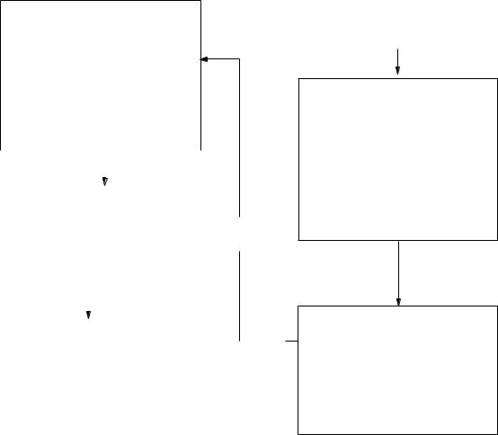
|
|
[RADAR 1] |
|
|
1 |
[SYSTEM SETTING 1] |
|
|
|
2 EBL1 (R-type only) |
REL/TRUE |
|||
3 EBL2 (R-type only) |
REL/TRUE |
|||
4 |
|
|
|
|
5 |
|
|
|
|
6 |
TRAIL |
REL/TRUE |
||
7 |
TRAIL GRAD |
SGL/MULT |
||
8[PULSEWIDTH 1] (IMO-type only)
9[PULSEWIDTH 2] (IMO-type only)
0RADAR2
|
|
|
|
|
|
|
|
|
|
|
|
Hit [9]. |
|
|
|
|
Hit [8]. |
|
|
|
|||
|
|
|
|
|
|
|
|
|
|
||
|
|
|
|
|
|
|
|
|
|
|
|
|
|
|
|
|
|
|
|
|
|
|
|
|
|
|
|
[PULSE WD 1] |
|
|
|
|
|||
|
1 |
[RADAR 1] |
|
|
|
S1/S2 |
|
|
|
||
|
2 |
0.5 |
NM |
|
|
|
|
|
|
||
-- (Blank |
on S-band) |
||||||||||
|
3 |
0.75 |
NM |
|
|
|
S1/S2 |
-- (S/M1 on S-band) |
|
||
|
4 |
1.5 |
NM |
|
|
|
S1/S2/M1 |
-- (S/M1 on S-band) |
|
||
|
5 |
3 |
NM |
|
|
|
S2/M1/M2 |
-- (S/M1/M2 on S-band) |
|
||
|
6 |
6 |
NM |
|
|
|
M1/M2/L |
|
|
|
|
|
7 |
12-24 |
NM |
|
|
|
M2/L |
|
|
|
|
|
|
|
|
|
|
|
|
|
|
|
|
|
|
|
|
|
|
|
|
|
|
|
|
|
|
|
|
|
|
|
|
|
|
|
|
|
|
|
|
|
|
|
|
|
|
|
|
|
[PULSE WD 2] |
|
|
|
|
|
|
1 |
[RADAR 1] |
S1/S2 |
|
|
|
Hit [2]. |
|||
|
|
|
|||||||
2 |
0.5 |
NM |
-- (Blank on S-band) |
|
|||||
3 |
0.75 |
NM |
S1/S2 |
-- (S/M1 on S-band) |
|
||||
4 |
1.5 |
NM |
S1/S2/M1 |
-- (S/M1 on S-band) |
|
||||
5 |
3 |
NM |
S2/M1/M2 |
-- (S/M1/M2 on S-band) |
|
||||
6 |
6 |
NM |
M1/M2/L |
|
|
|
|
|
|
7 |
12-24 |
NM |
M2/L |
|
|
|
|
|
|
|
|
|
|
|
|
|
|
|
|
Hit [RADAR MENU].
|
|
[FUNCTIONS 1] |
|
|
1 |
PULSE WIDTH |
1/2 |
|
|
2 |
ECHO STRETCH |
OFF/1/2 |
||
3 |
ECHO AVERAGE |
OFF/1/2/3 |
||
4 |
PANEL DIMMER |
OFF/DIM/M/BRT |
||
5 |
ECHO COLOR |
YEL/GRN/COLOR* |
||
6 |
SHIP'S SPEED |
LOG/NAV*/MAN |
||
7 |
INDEX LINES |
NO.2 VRM/MAN |
||
8 |
SET/DRIFT |
OFF/MAN |
||
|
|
|
SET 000.0 |
|
|
|
|
DRIFT 00.0 KT |
|
9 |
BRILLIANCE |
|
|
|
0 |
[SYSTEM SETTING 1] |
|
|
|
* R-type only
Hit [0].
[FUNCTIONS 2]
1[FUNCTIONS 1]
2RADAR 1
3FUNCTION KEY 1
4FUNCTION KEY 2
5FUNCTION KEY 3
6FUNCTION KEY 4
7 |
RADAR 2 |
1/2 |
8 |
ANCHOR WATCH |
|
9 |
|
|
0 |
[SYSTEM SETTING 2] |
|
1-13
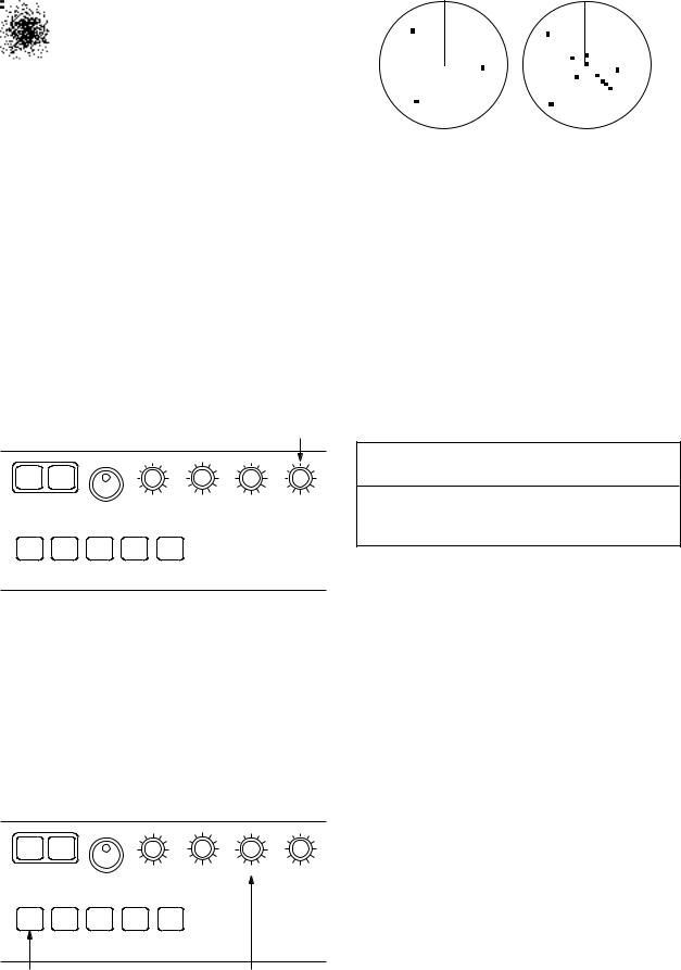
1.12 Adjusting the Sensitivity
The GAIN control is used to adjust the sensitivity of the receiver, and thus the intensity of echoes as they appear on the screen. It should be adjusted so that speckled background noise is just visible on the screen.
To become acquainted with the way the GAIN control works, try rotating it between fully counterclockwise and clockwise positions while observing the radar picture. You will notice that clockwise rotation increases the echo intensity level. A low gain setting results in the loss of weak echoes and a reduced detection range. If you turn the GAIN control too far clockwise for an excessive gain setting, desired echoes will be masked in the strong background noise.
GAIN control
OFF |
ON |
|
|
|
|
EBL |
|
BRILL |
A/C RAIN |
A/C SEA |
GAIN |
A/C |
FUNC1 |
FUNC2 FUNC3 FUNC4 |
|
|
|
AUTO |
|
|
|
||
|
|
|
|
|
A/C SEA control |
A/C SEA control |
off |
adjusted |
Automatic anti-clutter control
The easiest way to suppress the surface clutter is to use the automatic control. Press the A/C AUTO key next to the EBL rotary control at the left corner on the control panel. Use of a function key is also a good method for reducing sea clutter. For this purpose, presetting is required. Consult a FURUNO representative.
 CAUTION
The auto A/C function can erase weak targets.
1.13 Suppressing Sea Clutter
In rough weather conditions returns from the sea surface are received over several miles around own ship and mask close targets. This situation can be improved by properly adjusting the A/C SEA (Anti-Clutter Sea) control.
OFF |
ON |
|
|
|
|
EBL |
|
BRILL |
A/C RAIN |
A/C SEA |
GAIN |
A/C |
FUNC1 |
FUNC2 FUNC3 FUNC4 |
|
|
|
AUTO |
|
|
|
||
|
|
|
|
|
A/C AUTO key A/C SEA control
Manual anti-clutter control
From the fully counterclockwise position, slowly turn the A/C SEA control clockwise. For optimum target detection, you should leave speckles of the surface return slightly visible.
The anti-clutter sea control is often referred to as STC (Sensitivity Time Control) which decreases the amplification of the receiver immediately after a radar pulse is transmitted, and progressively increases the sensitivity as the range increases.
A common mistake is to over-adjust the A/C SEA control so that the surface clutter is completely removed. By rotating the control fully clockwise, you will see how dangerous this can be; a dark zone is created near the center of the screen and close-in targets can be lost. This dark zone is even more dangerous if the gain
1-14
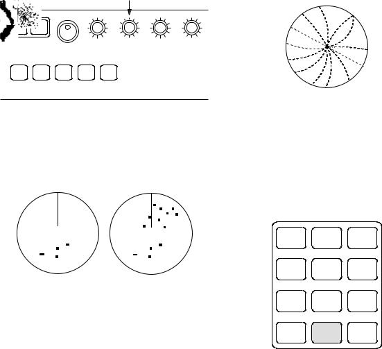
has not been properly adjusted. Always leave a little surface clutter visible on the screen. If no surface clutter is observed (on a very calm water), set the control at the fully counterclockwise position.
1.14Suppressing Precipitation Clutter
In adverse weather conditions, clouds, rain or snow produce a lot of spray-like spurious echoes and impairs target detection over a long distance. This situation can be improved by using a function key provided that it is so programmed. If the function key fails to offer a favorable suppression of the rain clutter, adjust the A/C RAIN control on the front control panel.
|
|
|
A/C RAIN |
|
|
|
|
control |
|
OFF |
ON |
|
|
|
EBL |
|
BRILL |
A/C RAIN A/C SEA |
GAIN |
A/C |
FUNC1 |
FUNC2 FUNC3 FUNC4 |
|
|
AUTO |
|
|
||
|
|
|
|
The A/C RAIN control adjusts the receiver sensitivity as the A/C SEA control does but rather in a longer time period (longer range). Clockwise rotation of this control increases the anti-clutter effect.
A/C RAIN control |
A/C RAIN control |
OFF |
adjusted |
1.15 Interference Rejector
Mutual radar interference may occur in the vicinity of another shipborne radar operating in the same frequency band (9 GHz for X-band, 3 GHz for S-band). It is seen on the screen as a number of bright spikes either in irregular patterns or in the form of usually curved spoke-like dotted lines extending from the center to the edge of the picture. This type of interference can be reduced by activating the interference rejector circuit.
The interference rejector is a kind of signal correlation circuit. It compares the received signals over successive transmissions and suppresses randomly occurring signals. There are three levels of interference rejection depending on the number of transmissions that are correlated. These are indicated by the legends IR1, IR2 and IR3 at the upper-left position of the screen.
Mutual radar interference
Press the INT REJECT key to activate the interference rejector circuit. Successive presses of the key increase the effect of interference rejection, up to level 3. A fourth press deactivates the interference rejector. Switch off the interference rejector when no interference exists; otherwise weak targets may be lost.
HL |
ECHO |
MODE |
|
OFF |
TRAILS |
||
|
|||
GUARDORIGIN |
VECTOR |
VECTOROFF |
|
EBL |
|||
ALMARKM |
TRUE/ |
CENTTIMER |
|
OFFSETREL |
|||
X2 |
BKGR |
INDEX |
|
ZOOM |
COLOR |
LINES |
|
CU, TM |
INT |
RINGS |
|
RESET |
REJECT |
||
|
Inside mode panel
1-15
Loading...