


 Loading...
OPERATOR'S MANUAL
MARINE RADAR
FAR-2807(-D) Series
MODEL FAR-2107(-BB,-D) Series
(Fishing Specification)
www.furuno.co.jp

The paper used in this manual is elemental chlorine free.
9-52 Ashihara-cho,
Nishinomiya, 662-8580, JAPAN
Telephone : +81-(0)798-65-2111
Fax |
: +81-(0)798-65-4200 |
All rights reserved. |
Printed in Japan |
Pub. No. OME-35220-B
(DAMI ) FAR-21X7/28X7(FISH)
FURUNO Authorized Distributor/Dealer
A : JAN. 2011
B : FEB. 18, 2011
*00017083511*
*00017083511*
* 0 0 0 1 7 0 8 3 5 1 1 *

IMPORTANT NOTICES
General
•The operator of this equipment must read and follow the descriptions in this manual. Wrong operation or maintenance can cancel the warranty or cause injury.
•Do not copy any part of this manual without written permission from FURUNO.
•If this manual is lost or worn, contact your dealer about replacement.
•The contents of this manual and equipment specifications can change without notice.
•The example screens (or illustrations) shown in this manual can be different from the screens you see on your display. The screens you see depend on your system configuration and equipment settings.
•Save this manual for future reference.
•Any modification of the equipment (including software) by persons not authorized by FURUNO will cancel the warranty.
•All brand and product names are trademarks, registered trademarks or service marks of their respective holders.
How to discard this product
Discard this product according to local regulations for the disposal of industrial waste. For disposal in the USA, see the homepage of the Electronics Industries Alliance (http://www.eiae.org/) for the correct method of disposal.
How to discard a used battery
Some FURUNO products have a battery(ies). To see if your product has a battery, see the chapter on Maintenance. Follow the instructions below if a battery is used. Tape the + and - terminals of battery before disposal to prevent fire, heat generation caused by short circuit.
In the European Union |
|
|
|
The crossed-out trash can symbol indicates that all types of |
|
|
|
batteries must not be discarded in standard trash, or at a trash |
|
|
|
site. Take the used batteries to a battery collection site |
|
|
|
according to your national legislation and the Batteries Directive |
|
Cd |
|
2006/66/EU. |
|
||
|
|
||
In the USA |
|
|
|
The Mobius loop symbol (three chasing arrows) indicates that |
|
|
|
Ni-Cd and lead-acid rechargeable batteries must be recycled. |
|
|
|
Take the used batteries to a battery collection site according to |
Ni-Cd |
Pb |
|
local laws. |
|||
|
|
In the other countries
There are no international standards for the battery recycle symbol. The number of symbols can increase when the other countries make their own recycling symbols in the future.
i

SAFETY INSTRUCTIONS
 WARNING
Radio Frequency Radiation Hazard
The radar antenna emits electromagnetic radio frequency (RF) energy which can be harmful, particularly to your eyes. Never look directly into the antenna aperture from a close distance while the radar ius in operation or eexpose yourself to the transmitting antenna at a close distance. Distances at which RF radiation level of 100, 50 and 10 W/m 2are given in the table below.
Note: If the antenna unit is installed at a close distance in front of the wheel house, your administration may require halt of transmission within a certain sector of antenna revolution. This is possible. Ask your FURUNO representive or dealer to provide this feature.
|
|
|
|
Distance to |
Distance to |
Radar model |
Trans. Unit |
Magnetron |
Antenna |
100 W/m2 |
10 W/m2 |
point |
point |
||||
|
|
|
|
|
|
FAR-2127/2827 |
RTR-079 |
MG5436 |
XN12AF |
0.90m |
9.00m |
FAR-2127/2827 |
RTR-079 |
MG5436 |
XN20AF |
0.50m |
4.60m |
FAR-2127/2827 |
RTR-079 |
MG5436 |
XN24AF |
0.20m |
3.30m |
FAR-2117/2817 |
RTR-078 |
*2 |
XN12AF |
0.30m |
3.70m |
MG4010 |
|||||
FAR-2117/2817 |
RTR-078 |
*2 |
XN20AF |
0.10m |
2.20m |
MG4010 |
|||||
FAR-2117/2817 |
RTR-078 |
*2 |
XN24AF |
0.10m |
1.50m |
MG4010 |
|||||
FAR-2137S |
RTR-080 |
MG5223F |
SN30AF |
0.10m |
2.40m |
FAR-2137S |
RTR-080 |
MG5223F |
SN36AF |
0.10m |
2.00m |
FAR-2157 |
RTR-083 |
9M31 |
XN4A |
1.20m |
13.6m |
FAR-2157 |
RTR-083 |
9M31 |
XN5A |
1.10m |
12.3m |
FAR-2167DS |
RTR-084 |
MG5240F |
SN30AF |
0.60m |
8.90m |
FAR-2167DS |
RTR-084 |
MG5240F |
SN36AF |
0.40m |
7.40m |
FAR-2827W |
RTR-081 |
MG5436 |
XN20AF |
2.20m |
13.00m |
FAR-2827W |
RTR-081 |
MG5436 |
XN24AF |
1.50m |
11.50m |
|
|
|
|
|
|
FAR-2837S |
RTR-080 |
MG5223F |
SN30AF |
0.10m |
2.40m |
FAR-2837S |
RTR-080 |
MG5223F |
SN36AF |
0.10m |
2.00m |
FAR-2837SW |
RTR-082 |
MG5223F |
SN36AF |
1.00m |
8.50m |
*1 XN12AF: 120cm, XN20AF: 198cm, XN24AF: 243cm, XN4A: 257cm, XN5A: 321cm, SN30AF: 309cm, SN36AF: 377cm
*2 Or MAF1425B
ii
 WARNING
ELECTRICAL SHOCK HAZARD
Do not open the equipment.
Only qualified personnel should work inside the equipment.
Turn off the radar power switch before servicing the antenna unit. Post a warning sign near the switch indicating it should not be turned on while the antenna unit is being serviced.
Prevent the potential risk of being struck by the rotating antenna and exposure to RF radiation hazard.
Wear a safety belt and hard hat when working on the antenna unit.
Serious injury or death can result if someone falls from the radar antenna mast.
Do not disassemble or modify the equipment.
Fire, electrical shock or serious injury can result.
Immediately turn off the power at the ship's mains switchboard if water leaks into the equipment or the equipment is emitting smoke or fire.
Continued use can cause fatal damage to the equipment.
SAFETY INSTRUCTIONS
 WARNING
Use the proper fuse.
Use of a wrong fuse can result in damage to the equipment or cause fire.
Keep heater away from equipment.
Heat can alter equipment shape and melt the power cord, which can cause fire or electrical shock.
Do not place liquid-filled containers near the equipment.
Fire or electrical shock can result if a liquid spills into the equipment.
Do not operate the equipment with wet hands.
Electrical shock can result.
Before servicing the radar, turn off the appropriate external breaker.
Power is not removed from the radar simply by turning off its power switch.
iii

SAFETY INSTRUCTIONS
 WARNING
No one navigational aid should be relied upon for the safety of vessel and crew. The navigator has the responsibility to check all aids available to confirm position. Electronic aids are not
a substitute for basic navigational principles and common sense.
•This ARP automatically tracks automatically or manually acquired radar targets and calculates their courses and speeds, indicating them by vectors. Since the data generated by the auto plotter are based on what radar targets are selected, the radar must always be optimally tuned for use with the auto plotter, to ensure required targets will not be lost or unwanted targets such as sea returns and noise will not be acquired and tracked.
•A target does not always mean a landmass, reef, ships or other surface vessels but can imply returns from sea surface and clutter. As the level of clutter changes with environment, the operator should properly adjust the A/C SEA, A/C RAIN and GAIN controls to be sure target echoes are not eliminated from the
radar screen.
WARNING LABEL
Warning labels are attached to the equipment. Do not remove any label. If a label is missing or damaged, contact a FURUNO agent or dealer about replacement.
 CAUTION
The plotting accuracy and response of this ARP meets IMO standards. Tracking accuracy is affected by the following:
•Tracking accuracy is affected by course change. One to two minutes is required to restore vectors to full accuracy after an abrupt course change. (The actual amount depends on gyrocompass specifications.)
•The amount of tracking delay is inversely proportional to the relative speed of the target. Delay is on the order of 15—30 seconds for high relative speed; 30—60 seconds for low relative speed.
The data generated by ARP, AIS and video plotter are intended for reference only.
Refer to official nautical charts for detailed and up-to-date information.
 WARNING
To avoid electrical shock, do not remove cover. No user-serviceable parts inside.

 WARNING
Radiation hazard. Only qualified personnel should work inside scanner. Confirm that TX has stopped before opening scanner.
DISPLAY UNIT, PROCESSOR UNIT
Name: Warning Label (1)
Type: 86-003-1011-1
Code No.: 100-236-231
ANTENNA UNIT
Name: Radiation Warning Label
Type: 03-142-3201-0
Code No.: 100-266-890
iv
TABLE OF CONTENTS
|
|
|
........................................................................................................FOREWORD |
xi |
|
PROGRAM NUMBER ........................................................................................ |
xiii |
|
SYSTEM CONFIGURATION.............................................................................. |
xiv |
|
SPECIFICATIONS........................................................................................... |
SP-1 |
|
1. RADAR OPERATION.................................................................................... |
1-1 |
|
1.1 |
Turning on the Power .................................................................................................. |
1-1 |
1.2 |
Transmitter ON ............................................................................................................ |
1-1 |
1.3 |
Control Unit ................................................................................................................. |
1-3 |
1.4 |
Main Menu................................................................................................................... |
1-5 |
1.5 |
Operation by the On-Screen Boxes ............................................................................ |
1-7 |
1.6 |
Cursor Menu.............................................................................................................. |
1-10 |
1.7 |
Monitor Brilliance........................................................................................................ |
1-11 |
1.8 |
Display Modes........................................................................................................... |
1-12 |
1.9 |
On-Screen Boxes and Markers ................................................................................. |
1-13 |
1.10 |
Tuning the Receiver .................................................................................................. |
1-15 |
|
1.10.1 Choosing the tuning method........................................................................... |
1-15 |
|
1.10.2 Initializing tuning ............................................................................................. |
1-15 |
|
1.10.3 Automatic tuning ............................................................................................. |
1-16 |
|
1.10.4 Manual tuning ................................................................................................. |
1-16 |
1.11 |
Aligning Heading with Gyrocompass......................................................................... |
1-16 |
1.12 |
Presentation Modes................................................................................................... |
1-17 |
|
1.12.1 Choosing presentation mode.......................................................................... |
1-17 |
|
1.12.2 Description of presentation modes ................................................................. |
1-18 |
1.13 |
Entering Own Ship's Speed....................................................................................... |
1-22 |
|
1.13.1 Automatic speed input by log or GPS navigator ............................................. |
1-22 |
|
1.13.2 Manual speed input ........................................................................................ |
1-23 |
1.14 |
Choosing a Range Scale........................................................................................... |
1-23 |
1.15 |
Choosing a Pulselength ............................................................................................ |
1-24 |
|
1.15.1 Choosing a pulselength .................................................................................. |
1-24 |
|
1.15.2 Changing pulselength ..................................................................................... |
1-25 |
1.16 |
Adjusting the Sensitivity ............................................................................................ |
1-26 |
1.17 |
Reducing Sea Clutter ................................................................................................ |
1-27 |
|
1.17.1 Choosing method of adjustment ..................................................................... |
1-27 |
|
1.17.2 Automatic reduction of sea clutter .................................................................. |
1-27 |
|
1.17.3 Manual reduction of sea clutter....................................................................... |
1-28 |
1.18 |
Reducing Rain Clutter ............................................................................................... |
1-29 |
|
1.18.1 Automatic reduction of rain clutter .................................................................. |
1-29 |
|
1.18.2 Manual reduction of rain clutter ...................................................................... |
1-29 |
1.19 |
Measuring Range ...................................................................................................... |
1-31 |
|
1.19.1 Showing, hiding the fixed range rings............................................................. |
1-31 |
|
1.19.2 Measuring range by the variable range marker (VRM)................................... |
1-32 |
|
1.19.3 VRM unit of measurement (B and C types) .................................................... |
1-33 |
|
1.19.4 TTG to VRM indication ................................................................................... |
1-33 |
1.20 |
Measuring Bearing .................................................................................................... |
1-34 |
|
1.20.1 Measuring bearing .......................................................................................... |
1-34 |
|
1.20.2 True or relative bearing................................................................................... |
1-35 |
1.21 |
Collision Assessment by Offset EBL ......................................................................... |
1-36 |
|
1.21.1 How to assess risk of collision by the offset EBL............................................ |
1-36 |
v
TABLE OF CONTENTS |
|
|
|
1.21.2 Point of reference for origin point of offset EBL............................................... |
1-37 |
1.22 |
Measuring Range and Bearing Between Two Targets ............................................... |
1-38 |
1.23 |
Target Alarm............................................................................................................... |
1-39 |
|
1.23.1 How to set a target alarm ................................................................................ |
1-39 |
|
1.23.2 Acknowledging the target alarm ...................................................................... |
1-40 |
|
1.23.3 Deactivating a target alarm.............................................................................. |
1-40 |
|
1.23.4 Target alarm attributes..................................................................................... |
1-41 |
1.24 |
Off-Centering the Display........................................................................................... |
1-42 |
1.25 |
Interference Rejector.................................................................................................. |
1-43 |
1.26 |
Echo Stretch............................................................................................................... |
1-43 |
1.27 |
Echo Averaging .......................................................................................................... |
1-44 |
1.28 |
Noise Rejector............................................................................................................ |
1-45 |
1.29 |
Wiper.......................................................................................................................... |
1-46 |
1.30 |
Target Trails................................................................................................................ |
1-47 |
|
1.30.1 True or relative trails........................................................................................ |
1-47 |
|
1.30.2 Trail time.......................................................................................................... |
1-48 |
|
1.30.3 Trail gradation.................................................................................................. |
1-48 |
|
1.30.4 Saving, copying target trails ............................................................................ |
1-49 |
|
1.30.5 Trail level ......................................................................................................... |
1-50 |
|
1.30.6 Narrow trails (B, C and W types)..................................................................... |
1-50 |
|
1.30.7 Longer trails (B, C and W types) ..................................................................... |
1-51 |
|
1.30.8 Temporarily removing trails from the display ................................................... |
1-51 |
|
1.30.9 Trail stabilization in true motion ....................................................................... |
1-51 |
|
1.30.10Erasing trails.................................................................................................. |
1-51 |
|
1.30.11 Preventing sea clutter in true trails ................................................................ |
1-52 |
1.31 |
PI (Parallel Index) Lines............................................................................................. |
1-52 |
|
1.31.1 Displaying, erasing PI lines ............................................................................. |
1-52 |
|
1.31.2 Adjusting PI line orientation, PI line interval .................................................... |
1-53 |
|
1.31.3 PI line bearing reference ................................................................................. |
1-53 |
|
1.31.4 Maximum number of PI lines to display........................................................... |
1-54 |
|
1.31.5 PI line orientation............................................................................................. |
1-54 |
|
1.31.6 Resetting PI lines ............................................................................................ |
1-54 |
1.32 |
Origin Mark................................................................................................................. |
1-55 |
|
1.32.1 Entering origin marks ...................................................................................... |
1-55 |
|
1.32.2 Origin mark stabilization .................................................................................. |
1-57 |
|
1.32.3 Deleting individual origin marks....................................................................... |
1-57 |
1.33 |
Zoom.......................................................................................................................... |
1-58 |
1.34 |
Markers ...................................................................................................................... |
1-59 |
|
1.34.1 Heading line .................................................................................................... |
1-59 |
|
1.34.2 Stern marker.................................................................................................... |
1-59 |
|
1.34.3 North marker ................................................................................................... |
1-59 |
|
1.34.4 Own ship symbol ............................................................................................. |
1-60 |
|
1.34.5 Barge marker................................................................................................... |
1-61 |
|
1.34.6 INS marker ...................................................................................................... |
1-61 |
1.35 |
Automatic Picture Setup According to Navigation Purpose ....................................... |
1-62 |
|
1.35.1 Selecting a picture setup option ...................................................................... |
1-64 |
|
1.35.2 Programming and saving picture setups ......................................................... |
1-64 |
|
1.35.3 Restoring user settings.................................................................................... |
1-66 |
|
1.35.4 Restoring default picture setup options ........................................................... |
1-66 |
|
1.35.5 Disabling unnecessary picture setups ............................................................. |
1-67 |
1.36 |
Function Keys ............................................................................................................ |
1-68 |
|
1.36.1 Activating function keys................................................................................... |
1-68 |
|
1.36.2 Programming function keys............................................................................. |
1-68 |
vi
|
TABLE OF CONTENTS |
|
1.37 |
Ship’s Position........................................................................................................... |
1-72 |
1.38 |
Second-trace Echoes ................................................................................................ |
1-74 |
1.39 |
Brilliance of Screen Data ........................................................................................... |
1-75 |
1.40 |
Watch Alarm .............................................................................................................. |
1-76 |
1.41 |
Nav Data ................................................................................................................... |
1-77 |
1.42 |
Text Window .............................................................................................................. |
1-79 |
1.43 |
Customizing Operation.............................................................................................. |
1-81 |
1.44 |
Alert Box.................................................................................................................... |
1-83 |
|
1.44.1 Alarm description ............................................................................................ |
1-84 |
|
1.44.2 Alarm list ......................................................................................................... |
1-87 |
|
1.44.3 Outputting alarm signals ................................................................................. |
1-88 |
|
1.44.4 Primary alarm ................................................................................................. |
1-89 |
1.45 |
Interswitch ................................................................................................................. |
1-90 |
|
1.45.1 Displaying antenna information ...................................................................... |
1-90 |
|
1.45.2 Presetting antenna and display combinations ................................................ |
1-91 |
|
1.45.3 Selecting an antenna ...................................................................................... |
1-93 |
1.46 |
Cursor Data ............................................................................................................... |
1-93 |
1.47 |
Performance Monitor................................................................................................. |
1-94 |
|
1.47.1 Activating, deactivating the performance monitor........................................... |
1-94 |
|
1.47.2 Checking radar performance .......................................................................... |
1-94 |
1.48 |
Own Ship Marker....................................................................................................... |
1-96 |
1.49 |
Color and Brilliance Sets ........................................................................................... |
1-97 |
|
1.49.1 Selecting color and brilliance set .................................................................... |
1-97 |
|
1.49.2 Presetting color and brilliance set................................................................... |
1-97 |
1.50 |
Reference Position .................................................................................................... |
1-99 |
1.51 |
Switching Hub HUB-100 (option) ............................................................................ |
1-101 |
1.52 |
Anchor Watch.......................................................................................................... |
1-102 |
1.53 |
Drop Mark................................................................................................................ |
1-103 |
|
1.53.1 Activating the drop mark feature................................................................... |
1-103 |
|
1.53.2 Inscribing a drop mark .................................................................................. |
1-104 |
|
1.53.3 Erasing a drop mark ..................................................................................... |
1-104 |
1.54 |
Sub Monitor (A, B, C and W types) ......................................................................... |
1-105 |
1.55 |
Net Cursor ............................................................................................................... |
1-106 |
|
1.55.1 Activating the net cursor ............................................................................... |
1-106 |
|
1.55.2 Setting net cursor dimensions, adjusting net cursor orientation ................... |
1-107 |
2. RADAR OBSERVATION ............................................................................... |
2-1 |
|
2.1 |
General........................................................................................................................ |
2-1 |
|
2.1.1 Minimum and maximum ranges........................................................................ |
2-1 |
2.2 |
False Echoes............................................................................................................... |
2-3 |
2.3 |
SART (Search and Rescue Transponder)................................................................... |
2-5 |
|
2.3.1 SART description .............................................................................................. |
2-5 |
|
2.3.2 Showing SART marks on the radar display ...................................................... |
2-6 |
|
2.3.3 General remarks on receiving SARTs............................................................... |
2-7 |
2.4 |
RACON ....................................................................................................................... |
2-8 |
2.5 |
Radar Target Enhancer (RTE)..................................................................................... |
2-8 |
3. TARGET TRACKING (TT)............................................................................. |
3-1 |
|
3.1 |
Usage Precautions ...................................................................................................... |
3-1 |
3.2 |
Controls for TT............................................................................................................. |
3-2 |
3.3 |
Activating, Deactivating TT.......................................................................................... |
3-3 |
3.4 |
Entering Own Ship's Speed......................................................................................... |
3-3 |
|
3.4.1 Echo-referenced speed input............................................................................ |
3-3 |
3.5 |
Automatic Acquisition .................................................................................................. |
3-5 |
vii
TABLE OF CONTENTS |
|
||
|
3.5.1 |
Enabling auto acquisition .................................................................................. |
3-5 |
|
3.5.2 Terminating tracking of targets (including reference targets)............................. |
3-6 |
|
3.6 |
Manual Acquisition ....................................................................................................... |
3-7 |
|
|
3.6.1 Setting manual acquisition conditions ............................................................... |
3-7 |
|
|
3.6.2 |
Manually acquiring targets................................................................................. |
3-7 |
3.7 |
Lost Target ................................................................................................................... |
3-9 |
|
|
3.7.1 Setting the lost target filter................................................................................. |
3-9 |
|
|
3.7.2 Enabling, disabling the lost target alarm............................................................ |
3-9 |
|
3.8 |
TT Symbols and Attributes ......................................................................................... |
3-10 |
|
|
3.8.1 |
TT symbols...................................................................................................... |
3-10 |
|
3.8.2 Choosing TT symbol (B, C and W types) ........................................................ |
3-11 |
|
|
3.8.3 |
TT symbol brilliance......................................................................................... |
3-11 |
|
3.8.4 |
TT symbol color............................................................................................... |
3-12 |
3.9 |
Displaying Target Data ............................................................................................... |
3-13 |
|
|
3.9.1 |
Displaying target data...................................................................................... |
3-13 |
|
3.9.2 |
Target list ......................................................................................................... |
3-15 |
3.10 |
Vector Modes ............................................................................................................. |
3-16 |
|
|
3.10.1 Description of vectors...................................................................................... |
3-16 |
|
|
3.10.2 Vector mode and length .................................................................................. |
3-17 |
|
3.11 |
Past Position Display ................................................................................................. |
3-18 |
|
|
3.11.1 Displaying and erasing past position points, choosing past |
|
|
|
|
position plot interval......................................................................................... |
3-18 |
|
3.11.2 Past position display attributes........................................................................ |
3-19 |
|
|
3.11.3 Past position display mode.............................................................................. |
3-19 |
|
|
3.11.4 Stabilization in true mode ................................................................................ |
3-20 |
|
3.12 |
Set and Drift ............................................................................................................... |
3-20 |
|
3.13 |
TT Collision Alarm (CPA, TCPA) ................................................................................ |
3-21 |
|
|
3.13.1 Setting the CPA and TCPA ranges .................................................................. |
3-21 |
|
|
3.13.2 Acknowledging the TT collision alarm ............................................................. |
3-22 |
|
3.14 |
Acquisition Zone......................................................................................................... |
3-22 |
|
|
3.14.1 Activating an acquisition zone ......................................................................... |
3-22 |
|
|
3.14.2 Sleeping, deactivating an acquisition zone...................................................... |
3-23 |
|
|
3.14.3 Acknowledging the alarm ................................................................................ |
3-23 |
|
|
3.14.4 Acquisition zone reference .............................................................................. |
3-24 |
|
|
3.14.5 Acquisition zone shape and stabilization......................................................... |
3-24 |
|
3.15 |
TT System Messages ................................................................................................ |
3-25 |
|
3.16 |
Trial Maneuver ........................................................................................................... |
3-26 |
|
|
3.16.1 Types of trial maneuvers ................................................................................. |
3-26 |
|
|
3.16.2 Performing a trial maneuver ............................................................................ |
3-27 |
|
|
3.16.3 Terminating a trial maneuver ........................................................................... |
3-29 |
|
3.17 |
TT Performance Test.................................................................................................. |
3-30 |
|
3.18 |
Criteria for Selecting Targets for Tracking .................................................................. |
3-32 |
|
3.19 |
Factors Affecting TT Functions................................................................................... |
3-34 |
|
4. AIS OPERATION........................................................................................... |
4-1 |
||
4.1 |
Controls for AIS............................................................................................................ |
4-1 |
|
4.2 |
Showing, Hiding the AIS Display.................................................................................. |
4-2 |
|
4.3 |
AIS Display Filter.......................................................................................................... |
4-4 |
|
4.4 |
Activating Targets......................................................................................................... |
4-5 |
|
|
4.4.1 Activating specific targets manually................................................................... |
4-5 |
|
|
4.4.2 |
Activating all targets .......................................................................................... |
4-5 |
4.5 |
How to Sleep Targets ................................................................................................... |
4-6 |
|
|
4.5.1 Sleeping an individual target ............................................................................. |
4-6 |
|
viii
|
|
TABLE OF CONTENTS |
|
|
4.5.2 |
Sleeping all targets ........................................................................................... |
4-6 |
4.6 |
Setting Up for a Voyage .............................................................................................. |
4-7 |
|
4.7 |
Target Data.................................................................................................................. |
4-9 |
|
|
4.7.1 |
Basic target data ............................................................................................... |
4-9 |
|
4.7.2 |
Detailed target data ......................................................................................... |
4-10 |
|
4.7.3 Removing a target data display ...................................................................... |
4-10 |
|
|
4.7.4 Canceling tracking on a target from target data display.................................. |
4-10 |
|
4.8 |
AIS Symbol Attributes................................................................................................. |
4-11 |
|
|
4.8.1 |
AIS symbol brilliance ....................................................................................... |
4-11 |
|
4.8.2 AIS symbol size and color ............................................................................... |
4-11 |
|
4.9 |
Past Position Display................................................................................................. |
4-12 |
|
|
4.9.1 Past position plot interval................................................................................ |
4-12 |
|
|
4.9.2 |
Past position points ......................................................................................... |
4-13 |
|
4.9.3 Past position display motion ........................................................................... |
4-13 |
|
|
4.9.4 Stabilization in true motion.............................................................................. |
4-13 |
|
4.10 |
Lost Target................................................................................................................. |
4-14 |
|
|
4.10.1 Lost target filter ............................................................................................... |
4-14 |
|
|
4.10.2 Enabling, disabling the lost target alarm......................................................... |
4-15 |
|
4.11 |
ROT Setting............................................................................................................... |
4-16 |
|
4.12 |
AIS Collision Alarm (CPA, TCPA) .............................................................................. |
4-17 |
|
|
4.12.1 Setting the CPA and TCPA ranges.................................................................. |
4-17 |
|
|
4.12.2 Enabling, disabling the AIS collision alarm ..................................................... |
4-17 |
|
|
4.12.3 Limiting the function of the collision alarm ...................................................... |
4-18 |
|
4.13 |
Association of TT and AIS Targets............................................................................. |
4-19 |
|
4.14 |
Own Ship’s Data........................................................................................................ |
4-21 |
|
4.15 |
Messages .................................................................................................................. |
4-22 |
|
|
4.15.1 Creating, saving messages ............................................................................ |
4-22 |
|
|
4.15.2 Transmitting messages................................................................................... |
4-23 |
|
|
4.15.3 Viewing messages.......................................................................................... |
4-24 |
|
4.16 |
AIS System Messages .............................................................................................. |
4-26 |
|
5. VIDEO PLOTTER OPERATION.................................................................... |
5-1 |
||
5.1 |
General........................................................................................................................ |
5-1 |
|
5.2 |
Display Modes............................................................................................................. |
5-1 |
|
5.3 |
Presentation Modes..................................................................................................... |
5-2 |
|
5.4 |
Radar Map................................................................................................................... |
5-3 |
|
|
5.4.1 Showing, hiding the radar map display............................................................. |
5-3 |
|
|
5.4.2 Inscribing radar map marks and lines............................................................... |
5-4 |
|
5.5 |
Erasing Radar Map Marks and Lines .......................................................................... |
5-6 |
|
|
5.5.1 Erasing individual radar map marks and lines .................................................. |
5-6 |
|
|
5.5.2 Erasing all radar map marks and lines ............................................................. |
5-7 |
|
5.6 |
Radar Map Corrections ............................................................................................... |
5-8 |
|
|
5.6.1 |
Radar map correction ....................................................................................... |
5-8 |
|
5.6.2 |
Cursor data correction ...................................................................................... |
5-8 |
5.7 |
Chart Cards (A, B, C and W types) ............................................................................. |
5-9 |
|
|
5.7.1 |
Displaying a chart ............................................................................................. |
5-9 |
|
5.7.2 |
Chart position correction ................................................................................. |
5-10 |
|
5.7.3 |
Correcting cursor data .................................................................................... |
5-10 |
|
5.7.4 Chart land color (B, C and W types) ................................................................ |
5-11 |
|
5.8 |
Hiding, Showing Graphics on the Video Plotter Display ......................................... |
5-12 |
|
5.9 |
Track |
.......................................................................................................................... |
5-13 |
|
5.9.1 .................................................................................Plotting own ship’s track |
5-13 |
|
|
5.9.2 ........................Plotting interval for other ships' tracks (A, B, C and W types) |
5-14 |
|
ix
TABLE OF CONTENTS |
|
|
|
5.9.3 Auto target track (A, B, C and W types) .......................................................... |
5-15 |
|
5.9.4 Choosing track color (A, B, C and W types).................................................... |
5-15 |
|
5.9.5 Erasing track from the menu, on the screen.................................................... |
5-16 |
|
5.9.6 Erasing track with the cursor ........................................................................... |
5-17 |
5.10 |
Waypoints .................................................................................................................. |
5-18 |
|
5.10.1 Entering waypoints .......................................................................................... |
5-18 |
|
5.10.2 Editing, erasing waypoints from the menu....................................................... |
5-20 |
|
5.10.3 Erasing waypoints ........................................................................................... |
5-21 |
|
5.10.4 Waypoint list .................................................................................................... |
5-22 |
|
5.10.5 Displaying waypoint name and number........................................................... |
5-23 |
5.11 |
Nav Lines ................................................................................................................... |
5-24 |
|
5.11.1 Entering a new nav line ................................................................................... |
5-24 |
|
5.11.2 Editing a nav line ............................................................................................. |
5-25 |
|
5.11.3 Nav line list ...................................................................................................... |
5-26 |
|
5.11.4 Erasing a nav line............................................................................................ |
5-27 |
|
5.11.5 Setting up nav lines ......................................................................................... |
5-28 |
|
5.11.6 Displaying nav line, waypoint mark ................................................................. |
5-30 |
5.12 |
Recording Data .......................................................................................................... |
5-32 |
|
5.12.1 Initializing memory (RAM) cards...................................................................... |
5-32 |
|
5.12.2 Recording data ................................................................................................ |
5-33 |
5.13 |
Replaying Data........................................................................................................... |
5-35 |
5.14 |
Deleting Files ............................................................................................................. |
5-36 |
6. MAINTENANCE, TROUBLESHOOTING...................................................... |
6-1 |
|
6.1 |
Periodic Maintenance Schedule................................................................................... |
6-2 |
6.2 |
Life Expectancy of Major Parts .................................................................................... |
6-3 |
6.3 |
Replacing the Fuse ...................................................................................................... |
6-4 |
6.4 |
Replacement of Battery on GC Board.......................................................................... |
6-4 |
6.5 |
Trackball Maintenance ................................................................................................. |
6-5 |
6.6 |
Easy Troubleshooting................................................................................................... |
6-6 |
6.7 |
Advanced-level Troubleshooting.................................................................................. |
6-7 |
6.8 |
Diagnostics................................................................................................................. |
6-10 |
APPENDIX ...................................................................................................... |
AP-1 |
|
1. Menu Tree ..................................................................................................................... |
AP-1 |
|
2. Digital Interface.............................................................................................................. |
AP-8 |
|
3. Longitude Error Table (on 96 nm range scale) ............................................................ |
AP-29 |
|
INDEX |
............................................................................................................... |
IN-1 |
Declaration of conformity
x

FOREWORD
A Word to the Owner of
FAR-2807(-D)/FAR-2107(-BB,-D) Series
Congratulations on your choice of the FURUNO FAR-2807(-D)/FAR-2107(-BB,-D) Series Radar. We are confident you will see why FURUNO has become synonymous with quality and reliability.
For 60 years FURUNO Electric Company has enjoyed an enviable reputation for innovative and dependable marine electronics equipment. This dedication to excellence is furthered by our extensive global network of agents and dealers.
Your radar is designed and constructed to meet the rigorous demands of the marine environment. However, no machine can perform its intended function unless installed, operated and maintained properly. Please carefully read and follow the recommended procedures for operation and maintenance.
We would appreciate hearing from you, the end-user, about whether we are achieving our purposes.
Thank you for considering and purchasing FURUNO equipment.
Features
•High-resolution 19-inch (FAR-2107-D), 20.1-inch LCD (FAR-2107(-BB)) or 23.1-inch LCD (FAR-2807(-D)).
•This series of radar are available in the models shown in the table below. 2107 series also available in "–BB", "-D" configuration. 2807 series also available in "–D" configuration. For example, FAR-2117-BB, FAR-2117-D.
Model |
Band |
Monitor |
Output |
TR config. |
|
|
|
|
10kW |
|
|
FAR-2117 |
|
17 inch |
10kW |
|
|
|
25kW |
|
|||
|
|
|
|
||
|
|
|
25kW |
UP |
|
FAR-2117 |
X-band |
20.1 inch |
10kW |
||
FAR-2127 |
25kW |
|
|||
|
|
||||
FAR-2157 |
|
|
50kW |
|
|
FAR-2817 |
|
23.1 inch |
10kW |
|
|
FAR-2827 |
|
25kW |
DOWN |
||
FAR-2827W |
|
|
25kW |
||
FAR-2137S |
|
20.1 inch |
30kW |
UP |
|
FAR-2167DS |
S-band |
60kW |
|||
|
|||||
FAR-2837S |
23.1 inch |
30kW |
|
||
|
|
||||
FAR-2837SW |
|
30kW |
DOWN |
||
|
|
xi
FOREWORD
•Two types of trackball-equipped control units are available: RCU-014 (full keyboard) and the RCU-015 (palm control). The trackball is easy to use thanks to the ergonomically designed palm rest.
•Simplified operation with point-and-click menu operation.
•All functions are accessible by using the trackball alone.
•Applicable to HSC (High Speed Craft)
•TT, AIS, Radar Plotter and Interswitch supplied as standard.
•Meets the requirements in IEC 62388 (Maritime navigation and radiocommunication equipment and systems - Shipborne radar - Performance requirements, methods of testing and required test results).
•Meets the requirements in IMO MSC.192(79).
•Meets the requirements in IEC 62288 (Maritime navigation and radiocommunication equipment and systems - Presentation of navigation-related information on shipborne navigational displays - General requirements, methods of testing and required test results).
•Target alarm watches for targets entering or exiting an alarm zone
•TCPA/CPA alarms
•Electronic parallel index lines
•42 rpm antenna for high speed craft
xii
Radar Type and Function Availability
This radar series is available in five specification types to meet the requirements of Authorities, and function availability depends on specification type. The table below shows those functions that have limited availability. This manual provides descriptions for all functions in this radar series, and we have endeavored to denote in the text those functions that have limited availability. For detailed information on function availability, see the menu tree in the Appendix.
•IMO: IMO compliant
•A: Near-IMO specifications
•B: Non-Japanese fishing vessels
•C: Japanese fishing vessels
•W: Washington state (USA) ferry
Specification type and function availability
Function |
|
|
Type |
|
|
|
IMO |
A |
B |
C |
W |
||
|
||||||
TT symbol |
No |
No |
Yes |
Yes |
Yes |
|
selection |
|
|
|
|
|
|
TT w/o gyro |
No |
No |
Yes |
Yes |
Yes |
|
Color echo |
No |
No |
Yes |
Yes |
Yes |
|
Mark w/line |
No |
No |
Yes |
Yes |
Yes |
|
Pop-up |
No |
No |
Yes |
Yes |
Yes |
|
guidance |
|
|
|
|
|
|
Range |
0.125, 0.25, |
Same as IMO |
0.125, 0.25, |
Same as B |
Same as B |
|
|
0.5, 0.75, 1.5, |
|
0.5, 0.75, 1, |
|
|
|
|
3, 6, 12, 24, |
|
1.5, 2, 3, 4, 6, |
|
|
|
|
48, 96 |
|
8, 12, 16, 24, |
|
|
|
|
|
|
32, 48, 96, |
|
|
|
|
|
|
120 |
|
|
|
Range unit |
nm only |
nm only |
nm, sm, km, |
nm, sm, km, |
nm, sm, km, |
|
|
|
|
kyd |
kyd |
kyd |
|
Stern-up |
No |
Yes |
Yes |
Yes |
Yes |
|
Trails-Narrow |
No |
No |
Yes |
Yes |
Yes |
|
Track-Other |
No |
Yes |
Yes |
Yes |
Yes |
|
ship |
|
|
|
|
|
|
Waypoint |
No |
No |
Yes |
Yes |
Yes |
|
mark |
|
|
|
|
|
xiii
PROGRAM NUMBER
|
|
|
|
|
|
|
|
|
|
|
PC Board |
Program No. |
Version No. |
|
|
|
|
|
|
|
MAIN |
035-9204 |
03.** (Merchant) |
|
|
|
|
|
|
|
RFC |
035-9202 |
01.** |
|
|
|
|
|
|
|
KEY(REMOTE) |
035-9203 |
01.** |
|
|
|
|
|
|
|
ARPA |
035-9212 |
01.** |
|
|
|
|
|
|
** Minor modification
xiv
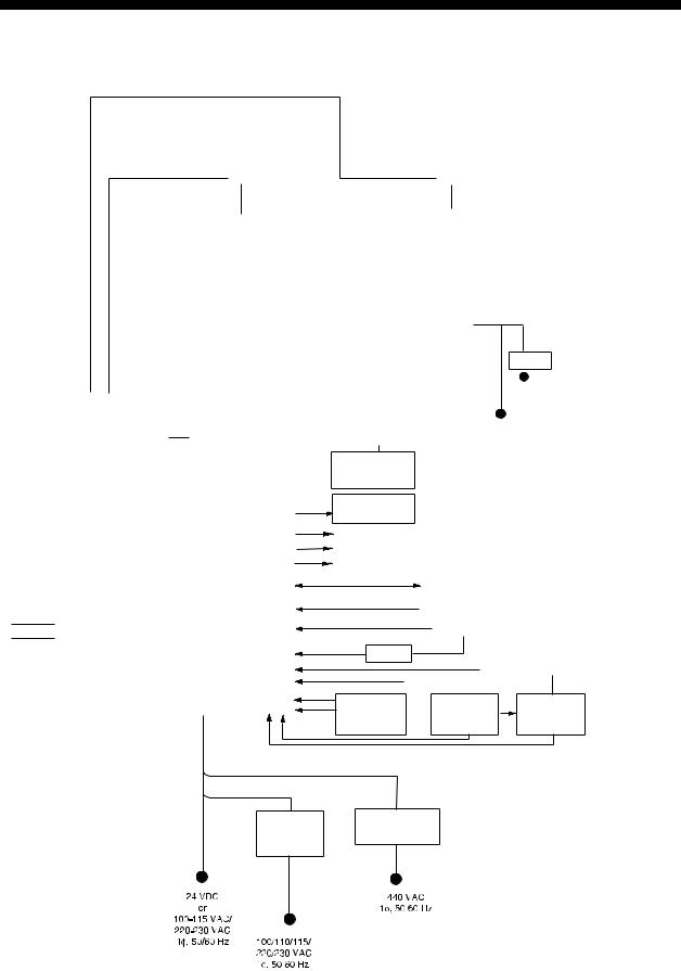
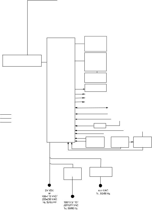
SYSTEM CONFIGURATION
See page xix for detailed information about antenna units and radiators.
With FURUNO-supplied monitor
|
|
|
FAR-2137S(-BB,-D)/2837S(-D)/2837SW(-D) |
FAR-2117(-BB,-D)/2127(-BB,-D)/ |
||||||||||||||||||||||||||||
|
|
|
2817(-D)/2827(-D)/2827W(-D) |
|
||||||||||||||||||||||||||||
|
|
|
|
|
|
|
|
|
|
|
|
|
|
|
|
|
|
|||||||||||||||
|
|
|
|
|
|
ANTENNA UNIT |
|
|
|
ANTENNA UNIT |
|
|||||||||||||||||||||
|
|
|
(Performance Monitor PM-51* built in) |
(Performance Monitor PM-31* built in) |
||||||||||||||||||||||||||||
|
|
|
|
|
|
|
|
|
|
|
|
|
|
|
|
|
|
|
|
|
|
|
|
|
|
|
|
|
|
|
|
|
|
|
|
|
|
|
|
|
|
|
|
|
|
|
|
|
|
|
|
|
|
|
|
|
|
|
|
|
|
|
|
|
|
|
|
|
|
|
|
|
|
|
|
|
|
|
Waveguide or |
|
|
|
|
|
|
|
|
|
|
|
Waveguide |
|
||||||
|
|
|
|
|
|
|
|
|
|
|
|
|
|
|
|
|
|
|
|
|
|
|
|
(For FAR-2827W(-D)) |
||||||||
|
|
|
|
|
|
|
|
|
|
|
|
|
|
|
|
|
|
|
|
|
|
|
|
|||||||||
|
|
|
|
|
|
|
|
|
|
|
|
|
Coax cable |
|
|
|
|
|
|
|
|
|
|
|
|
|
|
|
|
|||
|
|
|
|
|
|
|
|
|
|
|
|
|
(For FAR-2837SW(-D)) |
|
|
|
|
|
|
|
|
|
|
|
|
|
|
|
||||
|
|
|
|
|
|
TRANSCEIVER UNIT |
|
|
|
TRANSCEIVER UNIT |
|
|
||||||||||||||||||||
|
|
|
|
|
|
|
|
|
|
|
RTR-081 |
|
|
|||||||||||||||||||
|
|
|
|
|
|
RTR-082 |
|
|
|
|
|
|
|
|||||||||||||||||||
|
|
|
|
|
|
|
|
|
|
For FAR-2827W(-D) |
|
|
||||||||||||||||||||
|
|
|
|
|
|
For FAR-2837SW(-D) |
|
|
|
|
|
|
||||||||||||||||||||
|
|
|
|
|
|
|
|
|
|
|
|
|
|
|
|
|
|
|
|
|
|
|
|
|
|
|
|
|
* |
|
|
|
|
|
|
|
|
|
|
|
|
|
|
|
|
|
|
|
|
|
|
|
|
|
|
|
|
|
|
|
|
|
|
|
|
|
|
|
|
|
|
|
|
|
|
|
|
|
|
|
|
|
MONITOR UNIT |
|
|
|
|
|
|
|
|
|
|
|
|
|
||
|
|
|
|
|
|
|
|
|
|
|
|
|
|
|
|
|
MU-190 (FAR-2107-D) |
|
|
|
|
|
||||||||||
|
|
|
|
|
|
|
|
|
|
|
|
|
|
|
|
|
MU-201CR (FAR-2107(-BB,-D) |
|
|
|
|
|||||||||||
|
|
|
|
|
|
|
|
|
|
|
|
|
|
|
|
|
MU-231 (FAR-2107-D) |
|
|
|
|
|
|
|
|
|
|
|
24 VDC |
|||
|
|
|
|
|
|
|
|
|
|
|
|
|
|
|
|
|
MU-231CR (FAR-2107(-BB,-D) |
|
|
|
||||||||||||
|
|
|
|
|
|
|
|
|
|
|
|
|
|
|
|
|
|
|
|
|||||||||||||
|
|
|
|
|
|
|
|
|
|
|
|
|
|
|
|
|
|
|
|
|
|
|
|
|
|
|
|
|
|
|
RU-3423 |
|
|
|
|
|
|
|
|
|
|
|
|
|
|
|
|
|
|
|
|
|
|
|
|
|
|
|
|
|
|
|
|
||
|
|
|
|
|
|
|
|
|
|
|
|
|
|
|
|
|
|
|
|
|
|
|
|
|
|
|
|
|
|
|
|
|
|
|
|
|
|
|
|
|
|
|
|
|
|
|
|
|
|
CONTROL UNIT |
|
|
|
|
|
|
|
|
|
|
|
|
115/230 VAC |
||
|
|
|
|
|
|
|
|
|
|
|
|
|
|
|
|
|
RCU-014 |
|
|
|
|
|
|
|
|
|
|
|
|
|||
|
|
|
POWER SUPPLY UNIT |
|
|
|
|
|
|
|
|
|
|
|
|
|
|
|
|
|
|
|
|
|
|
|
|
|
|
|
||
|
|
|
|
|
|
|
|
|
|
|
|
|
|
|
|
(Keyboard) |
|
|
|
|
|
|
|
|
|
|
|
|
|
|
||
|
|
|
PSU-007 |
|
|
|
|
|
|
|
|
|
|
|
|
|
|
|
|
|
|
|
|
|
|
|
|
|
|
|
||
|
|
|
|
|
|
|
|
|
|
|
|
|
|
|
|
or |
|
|
|
|
|
|
|
|
|
|
|
|
|
|
||
|
|
(For FAR-2137S(-BB,-D)/2837S(-BB,-D)) |
|
|
|
|
|
|
|
|
|
|
|
|
|
RCU-015 |
|
|
|
|
|
|
|
|
|
|
24 VDC |
|
||||
|
|
|
OR |
|
|
|
|
|
|
|
|
|
|
|
|
|
(Trackball) |
|
|
|
|
|
|
|
|
|
|
or |
|
|||
|
|
|
POWER SUPPLY UNIT |
|
|
|
|
|
|
|
|
|
|
|
|
|
|
|
|
|
|
|
|
|
|
|
|
115/230 VAC |
||||
|
|
|
|
|
|
|
|
|
|
|
|
|
|
|
|
|
|
|
|
|
|
|
|
|
|
|||||||
|
|
|
PSU-011* |
|
|
|
|
|
|
|
|
|
|
|
|
|
Control Unit |
|
|
|
|
|
|
|
|
|
||||||
|
|
|
|
|
|
|
|
|
|
|
|
|
|
|
|
|
|
|
|
|
|
|
|
|
|
|
|
|
|
|||
|
|
(For FAR-2827W(-D)/2837SW(-D)) |
|
|
|
|
|
|
|
|
|
|
|
|
|
RCU-016 |
|
|
|
|
|
|
|
|
|
|
|
|
|
|
||
|
|
|
|
|
|
PROCESSOR UNIT |
|
|
(Remote) |
|
|
|
|
|
|
|
|
|
|
|
|
|
|
|||||||||
|
|
* Russian flag only |
|
|
|
|
|
|
|
|
|
|
|
|
|
|
|
|
|
|||||||||||||
|
|
|
|
|
|
|
|
|
|
|
|
|
|
|
|
|
|
|
|
|||||||||||||
|
|
|
|
|
|
RPU-013 |
|
Sub Display |
|
|
|
|
|
|
|
|
|
|
|
|
|
|
||||||||||
|
|
|
|
|
|
|
|
|
|
|
|
|
|
|
|
|
|
|
|
|
|
|
|
|
|
|
|
|
|
|
||
|
|
|
|
|
|
|
|
|
|
|
|
|
|
|
|
|
Alarm |
|
|
|
|
|
|
|
|
|
|
|
|
|
|
|
|
|
|
|
|
|
|
|
|
|
|
|
|
|
|
|
|
VDR |
|
|
|
|
|
|
|
|
|
|
|
|
|
|
|
|
|
|
|
|
|
|
|
|
|
|
|
|
|
|
|
|
External Monitor |
|
|
|
|
|
|
|
|
|
|
|
|
|
|
|
|
|
|
|
|
|
|
|
|
|
|
|
|
|
|
|
IEC-61162-1 Serial Data |
Navigator (INS, GPS, etc.) |
|||||||||||||||
|
|
|
|
|
|
|
|
|
|
|
|
|
|
|
|
|
(Input/Output) |
|
||||||||||||||
|
|
|
|
|
|
|
|
|
|
|
|
|
|
|
|
|
|
|
|
|
|
|
|
|
|
|
|
|
|
|
||
|
|
|
: Standard |
|
|
|
|
|
|
|
|
|
|
|
IEC-61162-1 Serial Data |
Speed Log |
|
|||||||||||||||
|
|
|
|
|
|
|
|
|
|
|
|
|
|
|
(Input) |
|
|
|||||||||||||||
|
|
|
: Option |
|
|
|
|
|
|
|
|
|
|
|
|
|
|
|
|
|
|
|
|
|
|
|
|
|
|
|||
|
|
|
|
|
|
|
|
|
|
|
|
|
|
|
|
|
|
|
|
Gyrocompass |
|
|||||||||||
|
|
|
: Dockyard supply |
|
|
|
|
|
|
|
|
|
|
|
|
|
|
|
|
|
|
|||||||||||
|
|
|
|
|
|
|
|
|
|
|
|
|
|
|
|
|
|
|
|
|
|
|
|
|
|
|
|
|
|
|
||
|
|
|
|
|
|
|
|
|
|
|
|
|
|
|
|
|
AD-100 |
|
|
|
|
|
|
|
|
|
|
|
|
|
||
Category of Units |
|
|
|
|
|
|
|
|
|
|
|
|
|
|
|
|
|
|
|
|
|
|
|
|
AIS |
100-230 VAC |
||||||
Antenna unit: Exposed to weather |
|
|
|
|
|
|
|
|
|
|
|
|
|
|
|
|
|
|
|
|
|
|
|
|
||||||||
|
|
|
|
|
|
|
|
|
|
|
|
|
|
Track Control Unit |
|
|||||||||||||||||
All other units: Protected from weather |
|
|
|
|
|
|
|
|
|
|
|
|
|
|
|
|||||||||||||||||
|
|
|
|
|
|
|
|
|
|
|
|
|
|
OR |
Memory Card |
|
||||||||||||||||
|
|
|
|
|
|
|
|
|
|
|
|
|
|
|
|
|
Memory Card |
|
||||||||||||||
|
|
|
|
|
|
|
|
|
|
|
|
|
|
|
|
|
|
|
Switching Hub |
|||||||||||||
|
|
|
|
|
|
|
|
|
|
|
|
|
|
|
|
|
Interface Unit |
|
|
Interface Unit |
||||||||||||
|
|
|
|
|
|
|
|
|
|
|
|
|
|
|
|
|
|
|
HUB-100 |
|||||||||||||
|
|
|
|
|
|
|
|
|
|
|
|
|
|
|
|
|
CU-200 |
|
|
|
CU-200 x 2 |
|||||||||||
|
|
|
|
|
|
|
|
|
|
|
|
|
|
|
|
|
|
|
|
|
||||||||||||
|
|
|
|
|
|
|
|
|
|
|
|
|
|
HUB has ports for connection of up to 7 processor units |
||||||||||||||||||
|
AC spec |
DC spec |
|
Rectifier |
Transformer Unit |
RU-3424 |
RU-1803 |
RU-1746B-2 |
|
*These monitors have been approved by the IMO, MU-190/201CR for CAT2, MU-231/231CR for CAT1.
If a different monitor is to be used, its effective diameter must meet the applicable Category requirements:
CAT 1: effective diameter 320 mm or higher CAT 2: effective diameter 250 mm or higher For installation and operation of other monitor, see its manuals.
xv
SYSTEM CONFIGURATION
Blackbox type
|
|
FAR-2137S-BB |
FAR-2117-BB/2127-BB |
||||||||||||||||
|
|
ANTENNA UNIT |
|
|
ANTENNA UNIT |
||||||||||||||
(Performance Monitor PM-51 built in |
(Performance Monitor PM-31 built in |
||||||||||||||||||
|
|
(FAR-2137S-BB) |
(FAR-2117-BB, FAR-2127-BB) |
||||||||||||||||
|
|
|
|
|
|
|
|
|
|
|
|
|
|
|
|
|
|
|
|
|
|
|
|
|
|
|
|
|
|
|
|
|
|
|
|
|
|
|
|
|
|
|
|
|
|
|
|
|
|
|
|
|
|
|
|
|
|
|
|
|
|
|
|
|
|
|
|
|
|
|
|
|
|
|
|
|
|
|
|
|
|
|
|
|
|
|
|
|
|
|
|
|
|
|
|
|
|
|
|
|
|
|
|
|
|
|
|
|
|
|
|
|
|
|
|
|
|
|
|
|
VGA Monitor |
|
|
|
POWER SUPPLY UNIT |
CONTROL UNIT |
|
|
|
RCU-014 |
|
|
|
|
PSU-007 |
(Keyboard) |
|
|
|
For FAR-2137S-BB |
or |
|
|
|
|
RCU-015 |
|
|
|
|
(Trackball) |
|
|
|
|
Control Unit |
|
|
|
|
RCU-016 |
|
|
|
PROCESSOR UNIT |
(Remote) |
|
|
|
|
|
|
|
|
RPU-013 |
Sub Display |
|
|
|
|
|
|
|
|
|
Alarm |
|
|
|
|
VDR |
|
|
|
|
External Monitor |
|
|
|
|
IEC-61162-1 Serial Data |
Navigator (INS, GPS, etc.) |
||
|
(Input/Output) |
|||
|
|
|
|
|
: Standard |
IEC-61162-1 Serial Data Speed Log |
|
||
(Input) |
|
|
|
|
|
|
|
|
|
: Option |
|
|
Gyrocompass |
|
|
|
|
|
|
: Dockyard supply |
|
|
|
|
|
AD-100 |
|
|
|
Category of Units |
|
|
AIS |
100-230 VAC |
Antenna unit: Exposed to weather |
Track Control Unit |
|
||
All other units: Protected from weather |
Memory Card OR |
Memory Card |
|
|
|
Switching Hub |
|||
|
Interface Unit |
|
Interface Unit |
|
|
|
HUB-100 |
||
|
CU-200 |
|
CU-200 x 2 |
|
|
|
|
||
HUB has ports for connection of up to 7 processor units |
||||
|
AC spec |
|
|
|
DC spec |
|
|
|
|
Rectifier |
Transformer Unit |
|
|
|
RU-3424 |
RU-1803 |
|
|
|
RU-1746B-2 |
|
|
|
|
xvi
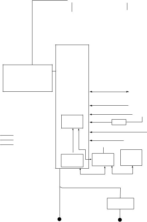
|
|
|
|
|
|
|
|
|
|
|
|
|
SYSTEM CONFIGURATION |
|||||||
Console type RCN-001/RCN-002 |
|
|
|
|
|
|
|
|
|
|
|
|||||||||
|
|
|
|
|
|
|
|
|
|
|
|
|
FAR-2117(-D)/2127(-D)/ |
|||||||
FAR-2137S(-D)/2837S(-D)/2837SW(-D) |
|
|
2817(-D)/2827(-D)/2827W(-D) |
|||||||||||||||||
|
|
ANTENNA UNIT |
|
|
|
ANTENNA UNIT |
||||||||||||||
(Performance Monitor PM-51 built in) |
(Performance Monitor PM-31 built in) |
|||||||||||||||||||
|
|
|
|
|
|
|
|
|
|
|
|
|
|
|
|
|
|
|
|
|
|
|
|
|
|
|
|
|
|
|
|
|
|
|
|
|
|
|
|
|
|
|
|
|
|
|
|
|
Waveguide or |
|
|
|
|
|
|
|
|
Waveguide |
||||
|
|
|
|
|
|
|
|
|
|
|
|
|
|
|
||||||
|
|
|
|
|
|
|
|
|
|
|
|
|
|
|
(For FAR-2827W(-D)) |
|||||
|
|
|
|
|
|
|
|
|
|
|
||||||||||
|
|
|
|
|
|
|
Coax cable |
|
|
|
|
|
|
|
|
|
|
|
||
|
|
|
|
|
|
|
(For FAR-2837SW(-D)) |
|
|
|
||||||||||
|
|
TRANSCEIVER UNIT |
|
|
|
|
TRANSCEIVER UNIT |
|
||||||||||||
|
|
|
|
|
|
RTR-081 |
|
|||||||||||||
|
|
RTR-082 |
|
|
|
|
|
|||||||||||||
|
|
|
|
|
|
For FAR-2827W(-D) |
|
|||||||||||||
|
|
For FAR-2837SW(-D) |
|
|
|
|
|
|||||||||||||
|
|
|
|
|
|
|
|
|
|
|
|
|
|
|||||||
|
|
|
|
|
|
|
|
|
|
|
|
|
|
|
|
|
|
|
|
|
|
|
|
|
|
|
|
|
|
|
|
|
|
|
|
|
|
|
|
|
|
POWER SUPPLY UNIT
PSU-007
For FAR-2137S(-D)/2837S(-D)
OR
POWER SUPPLY UNIT
PSU-011*
(For FAR-2827W(-D)/2837SW(-D)
* Russian flag only
:Standard
:Option
:Dockyard supply
Category of Units
Antenna unit: Exposed to weather All other units: Protected from weather
CONSOLE
RCN-001/002
PROCESSOR
UNIT
RPU-013
OR
May also be installed externally. 
Memory Card
Interface Unit
CU-200
 Alarm
Alarm
 VDR
VDR
 External Monitor
IEC-61162-1 Serial Data |
Navigator (INS, GPS, etc.) |
|
(Input/Output) |
||
|
IEC-61162-1 Serial Data Speed Log
(Input)
Gyrocompass
AD-100
AIS
Track Control Unit
100-230 VAC |
|
|
|
Memory Card |
|
Switching Hub |
Interface Unit |
|
CU-200 |
||
HUB-100 |
||
(Max. 2 total) |
||
|
AC spec
Transformer Unit
RU-1803
100-115 VAC/ |
440 VAC |
220-230 VAC |
1φ, 50/60 Hz |
1φ, 50/60 Hz |
|
xvii
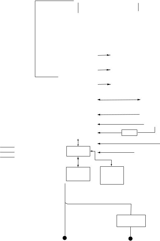
SYSTEM CONFIGURATION
Console type RCN-003/RCN-004
|
|
|
|
|
|
|
|
|
|
|
|
|
FAR-2117(-BB,-D)/2127(-D)/2817(-D)/ |
|||||||
FAR-2137S(-D)/2837S(-D)/2837SW(-D) |
|
|
|
|
|
2827(-D)/2827W(-D) |
||||||||||||||
|
|
ANTENNA UNIT |
|
|
|
ANTENNA UNIT |
||||||||||||||
(Performance Monitor PM-51 built in) |
(Performance Monitor PM-31 built in) |
|||||||||||||||||||
|
|
|
|
|
|
|
|
|
|
|
|
|
|
|
|
|
|
|
|
|
|
|
|
|
|
|
|
|
|
|
|
|
|
|
|
|
|
|
|
|
|
|
|
|
|
|
|
|
Waveguide or Coax cable |
|
|
|
|
|
|
Waveguide |
||||||
|
|
|
|
|
|
|
|
|
|
|
|
|
||||||||
|
|
|
|
|
|
|
|
|
|
|
|
|
||||||||
|
|
|
|
|
|
(For FAR-2837SW(-D)) |
|
|
|
|
|
(For FAR-2827W(-D)) |
||||||||
|
|
|
|
|
|
|
|
|
|
|
|
|
|
|
|
|
|
|
|
|
|
|
TRANSCEIVER UNIT |
|
|
|
|
TRANSCEIVER UNIT |
|
||||||||||||
|
|
|
|
|
|
RTR-081 |
|
|||||||||||||
|
|
RTR-082 |
|
|
|
|
|
|||||||||||||
|
|
|
|
|
|
For FAR-2827W(-D) |
|
|||||||||||||
|
|
For FAR-2837SW(-D) |
|
|
|
|
|
|||||||||||||
|
|
|
|
|
|
|
|
|
|
|
|
|
|
|||||||
|
|
|
|
|
|
|
|
|
|
|
|
|
|
|
|
|
|
|
|
|
|
|
|
|
|
|
|
|
|
|
|
|
|
|
|
|
|
|
|
|
|
:Standard
:Option
:Dockyard supply
Category of Units
Antenna unit: Exposed to weather All other units: Protected from weather
|
|
CONSOLE |
Alarm |
|
||
|
|
RCN-003/004 |
|
|||
|
|
|
|
|||
|
|
|
|
|
|
|
|
|
POWER SUPPLY UNIT |
|
VDR |
|
|
|
|
PSU-007 |
|
|
||
|
(For FAR-2137S(-D)/2837S(-D)) |
|
|
|
||
|
|
OR |
|
|
|
|
|
|
POWER SUPPLY UNIT |
|
|
|
|
|
|
PSU-011* |
|
External Monitor |
|
|
|
(For FAR-2827W(-D)/2837SW(-D)) |
|
|
|||
|
|
|
|
|||
|
|
|
|
|
|
|
|
* Russian flag only |
IEC-61162-1 Serial Data |
|
|||
|
|
|
|
|
Navigator (INS, GPS, etc.) |
|
|
|
|
|
|
(Input/Output) |
|
|
|
|
|
|
|
|
|
|
|
|
|
IEC-61162-1 Serial Data |
Speed Log |
|
|
|
|
|
(Input) |
|
|
|
|
|
|
|
Gyrocompass |
|
|
PROCESSOR |
|
|
|
|
|
|
UNIT |
|
AD-100 |
|
|
|
|
RPU-013 |
|
|
|
|
|
|
|
|
|
||
|
|
|
|
|
|
AIS |
|
|
|
|
|
|
|
|
|
Switching Hub |
Track Control Unit |
|||
|
|
HUB-100 |
||||
|
|
Memory Card |
Memory Card |
|
||
|
|
Interface Unit |
Interface Unit |
|
||
|
|
CU-200 |
CU-200 |
|
||
|
|
|
|
|
(Max. 2 total) |
|
AC spec
Transformer Unit
RU-1803
100-115 VAC/ |
440 VAC |
220-230 VAC |
1φ, 50/60 Hz |
1φ, 50/60 Hz |
|
xviii
Antenna unit
FAR-2117(-BB,-D) FAR-2127(-BB,-D) FAR-2827(-D)
FAR-2137S(-BB,-D)
FAR-2157(-BB,-D)
FAR-2167DS(-BB,-D)
FAR-2827W(-D)
FAR-2837S(-D)
FAR-2837SW(-D)
Radiator
SYSTEM CONFIGURATION
RSB-096 (24 rpm)
RSB-097 (42 rpm)
RSB-098/099 (21/26 rpm, 200 VAC, 3ø, 50 Hz; 220 VAC, 3ø, 60 Hz; 380 VAC, 3ø, 50 Hz, 440 VAC, 3ø, 60 Hz)
RSB-100/101/102 (45 rpm, 220 VAC, 3ø, 50/60 Hz(HSC); 440 VAC, 3ø, /60 Hz(HSC))
RSB-106 (18/22 rpm, 200 VAC, 3ø, 50Hz, 220 VAC, 3ø, 60 Hz) RSB-107 (22 rpm, 24 VDC)
RSB-111 (21/26 rpm, 200 VAC, 3ø, 50Hz, 220 VAC, 3ø, 60Hz) RSB-112 (21/26 rpm, 380 VAC, 3ø, 50Hz, 440 VAC, 3ø, 60Hz)
RSB-103 (24 rpm, powered by processor unit)
Same as FAR-2137S
RSB-104/105 (21/26 rpm, 200 VAC, 3ø, 50 Hz; 220 VAC, 3ø, 60 Hz; 380 VAC, 3ø, 50 Hz, 440 VAC, 3ø, 60 Hz)
FAR-2117(-BB,-D), FAR-2127(-BB,-D), FAR-2827(-D) |
XN12AF , XN20AF, XN24AF |
|
|
FAR-2137S(-BB,-D) |
SN30AF, SN36AF |
|
|
FAR-2157(-BB,-D) |
XN4A, XN5A |
|
|
FAR-2167DS(-BB,-D) |
SN30AF, SN36AF |
|
|
FAR-2827W(-D) |
XN20AF, XN24AF |
|
|
FAR-2837S(-D) |
SN30AF, SN36AF |
|
|
FAR-2837SW(-D) |
SN30AF, SN36AF |
|
|
xix
SYSTEM CONFIGURATION
This page intentionally left blank.
xx

FURUNO
FAR-2157/2167DS
SPECIFICATIONS OF MARINE RADAR/ARPA
FAR-2157/2167DS
1 |
ANTENNA RADIATOR |
|
1.1 |
Type |
Slotted waveguide array |
1.2Beam width and sidelobe attenuation
|
Radiator type |
X-band |
|
S-band |
|
||||
|
XN4A |
|
XN5A |
|
SN30AF |
|
SN36AF |
|
|
|
|
|
|
|
|
||||
|
Length |
8 ft |
|
10 ft |
|
9.5 ft |
|
12 ft |
|
|
Beam width(H) |
0.75° |
|
0.75° |
|
2.3° |
|
1.8° |
|
|
Beam width(V) |
20° |
|
|
25° |
|
|||
|
Sidelobe within ±10° |
-28 dB |
|
-26 dB |
|
-24 dB |
|
||
|
Sidelobe outside ±10° |
-32 dB |
|
-30 dB |
|
-30 dB |
|
||
|
Applicable type |
FAR- |
2157 |
|
FAR-2167DS |
|
|||
1.3 |
Polarization |
Horizontal |
|
|
|
|
|
|
|
1.4 |
Rotation |
|
|
|
|
|
|
|
|
|
FAR-2157 |
RSB-106: 18 rpm (50 Hz)/22 rpm (60 Hz), RSB-107: 22 rpm |
|||||||
|
FAR-2167DS |
21 rpm (50 Hz), 26 rpm (60 Hz) |
|
|
|||||
1.5 |
Wind tolerance |
Relative wind 100 kn |
|
|
|
|
|||
1.6 |
De-icer (option) |
On: When temperature goes down to +5°C |
|||||||
|
|
Off: When temperature goes up to +12°C |
|||||||
2 RF TRANSCEIVER
2.1Frequency
X-band |
9410 MHz ±30 MHz |
S-band |
3050 MHz ±30 MHz |
2.2Output power
FAR-2157 |
50 kW |
FAR-2167DS |
60 kW |
2.3Range, pulse repetition frequency (PRF), pulselength
|
PRF (Hz) |
|
|
|
|
|
|
|
|
|
|
Range (NM) |
|
|
|
|
|
|
|
|
|
|||||
|
|
|
0.125 |
0.25 |
0.5 |
0.75 |
1 |
1.5 |
2 |
3 |
|
4 |
6 |
|
8 |
12 |
16 |
24 |
|
32 |
48 |
72 |
96 |
120 |
||
|
1900 (SP) |
|
|
|
|
0.08 µs |
|
|
|
|
|
|
|
|
|
|
|
|
|
|
|
|
|
|
||
|
1100 (MP) |
|
|
|
|
|
|
|
0.2 µs |
|
|
|
|
|
|
|
|
|
|
|
|
|
|
|
||
|
600 (LP) |
|
|
|
|
|
|
|
|
|
|
|
|
|
0.6 µs |
|
|
|
|
|
|
|
|
|||
|
600 (LP) |
|
|
|
|
|
|
|
|
|
|
|
|
|
|
|
|
|
|
1.2 µs |
|
|
|
|
||
|
2nd traced echo reduce mode (w/o short pulse): 500 Hz approx. |
|
|
|
|
|
|
|
|
|||||||||||||||||
2.4 Duplexer |
|
|
|
Ferrite circulator with diode limiter |
|
|
|
|
|
|
|
|
||||||||||||||
3 |
MONITOR UNIT |
|
3.1 |
Screen |
Raster scan, daylight bright, yellow or green echoes in 32 levels |
3.2 |
Scanning |
Non-Interlace at 64 kHz horizontal, 60 Hz vertical |
3.3 |
Display |
|
|
Size |
20.1-inch color LCD |
|
Display area |
399 x 319 mm |
SP - 1 |
E3522S01A-M |
FURUNO
FAR-2157/2167DS
|
Resolution |
1280 x 1024 pixel |
|
Effective radar diameter |
308 mm (H: 64 kHz, V: 60 Hz) |
|
Viewable range |
1080 mm |
3.4 |
Minimum range |
22 m |
3.5 |
Range discrimination |
26 m |
3.6Range scales, Ring interval, Number of rings
Range (NM) |
0.125 |
|
0.25 |
|
0.5 |
0.75 |
1 |
|
1.5 |
|
2 |
3 |
4 |
6 |
8 |
12 |
Ring interval (NM) |
0.025 |
|
0.05 |
|
0.1 |
0.25 |
0.25 |
|
0.25 |
|
0.5 |
0.5 |
1 |
1 |
2 |
2 |
Number of rings |
5 |
|
5 |
|
5 |
3 |
6 |
|
6 |
|
4 |
6 |
4 |
6 |
4 |
6 |
|
|
|
|
|
|
|
|
|
|
|
|
|
|
|
|
|
|
16 |
|
24 |
|
32 |
48 |
72 |
|
96 |
|
120 |
|
|
|
|
|
|
4 |
|
4 |
|
8 |
8 |
12 |
|
16 |
|
20 |
|
|
|
|
|
|
4 |
|
6 |
|
4 |
6 |
6 |
|
6 |
|
6 |
|
|
|
|
|
3.7 |
Range accuracy |
1% of the maximum range of the scale in use or 10m, |
|
|
whichever is the greater |
3.8 |
Bearing discrimination |
1.18° (XN4A), 0.98° (XN5A), 2.5° (SN30AF), 2.0° (SN36AF) |
3.9 |
Bearing accuracy |
±1° |
3.10 |
Presentation mode |
Head-up, Cursor-gyro, Course-up, North-up, |
|
|
True motion (sea or ground stabilization) |
3.11 |
ARPA |
Auto or manual acquisition: 100 targets in 0.2-24(32) NM |
|
|
Auto tracking on all acquired targets |
|
|
Tracking: 5/10 pts on all target |
3.12 |
AIS |
Capacity: 1000 targets, Tracking: 10 pts on all target |
|
|
Time of vector: Off/30s/1-60 minutes |
3.13 |
Radar map |
20,000 pts in radar mode, 6000 pts on IC card in chart mode |
3.14 |
Acquisition zone |
2 zones |
3.15 |
Interswitch function |
Selectable from menu |
4 |
INTERFACE |
|
4.1 |
Heading signal |
Synchro signal (20-100VDC or 20-135VAC 50/60/400/500Hz) or |
|
|
Stepper signal (20-100VDC), built-in interface (option) required, |
|
|
AD-10 format or IEC61162-2 |
4.2 |
Speed log |
IEC61162-1 |
4.3 |
AIS |
IEC61162-2 |
4.4 |
Input data sentences |
ABK, ACK, ALR, BWC, BWR, DBK, DBS, DBT, DPT, DTM, GGA, |
|
|
GLL, HDT, MTW, MWV, RMB, RMC, RTE, THS, VBW, VDM, VDO, |
|
|
VDR, VHW, VTG, VWR, VWT, WPL, ZDA |
4.5Output data sentences ABM, ACK, ALR, BBM, OSD, RSD, TLB, TLL, TTD, TTM, VSD
5 |
POWER SOURCE |
|
5.1 |
Monitor unit |
24 VDC:2.3 A or 100-230 VAC: 0.7 A, 1 phase, 50/60 Hz |
5.2 |
Processor unit |
24VDC or 100-115/220-230 VAC: 3.0/1.5A, 1 phase, 50/60 Hz |
5.3Power supply unit
FAR-2157 main |
100-115/220-230 VAC: 4.4/2.0A, 1 phase, 50/60 Hz |
FAR-2157 motor |
24VDC: 4A or 200/220 VAC: 2.0A, 3 phase, 50/60 Hz |
SP - 2 |
E3522S01A-M |
FURUNO |
|
|
|
|
|
FAR-2157/2167DS |
||
|
FAR-2167DS |
220/380VAC: 3/1.5A, 3 phase, 50 |
Hz or |
|||||
|
|
220/440VAC: 3/1.5A, 3 phase, 60 |
Hz |
|||||
5.4 |
Antenna unit |
200/220/380/440 VAC, 3 phase, 50/60 Hz |
||||||
|
|
|
|
|
|
|
||
|
|
Model |
|
Antenna voltage input (100 kn) |
|
|||
|
|
200 |
VAC, 3 |
φ 50 Hz, |
380 VAC, 3 φ, 50 Hz, |
|
||
|
|
|
220 |
VAC, 3 |
φ, 60 Hz |
|
440 VAC, 3 φ, 60 Hz |
|
5.5 |
Console |
FAR-2167DS |
|
3.0 A |
|
1.5 A |
|
|
115/230 VAC, |
1 phase, 50/60 Hz |
|
|
|||||
5.6Transformer (option)
For single phase |
RU-1803: 440 VAC, 1 phase, 50/60 Hz |
For triple phase |
RU-5693: 110 VAC, 3 phase, 60 Hz |
|
RU-6522: 220 VAC, 3 phase, 50 Hz |
|
RU-5466-1: 440 VAC, 3 phase, 50 Hz |
6 ENVIRONMENTAL CONDITIONS
6.1Ambient temperature Monitor/processor/transceiver/control/power supply unit
|
-15°C to +55°C |
Antenna unit |
-25°C to +55°C (storage +70°C) |
6.2 Relative humidity |
95% max. at 40°C |
6.3Degree of protection
|
Monitor/processor/control/power supply unit |
IPX0 |
|
|
Antenna unit |
IPX6 |
|
6.4 |
Vibration |
IEC60945 Ed.4 |
|
7 |
COLOR |
|
|
7.1 |
Monitor unit |
Chassis: 2.5GY5/1.5, Panel: N3.0 (fixed) |
|
7.2 |
Processor/power supply unit 2.5GY5/1.5 |
|
|
7.3 |
Control unit |
N3.0 (fixed) |
|
7.4 |
Antenna unit |
N9.5 (fixed) |
|
8 PERFORMANCE MONITOR (PM-50)
8.1PM-30 (X-band)
8.1.1 |
Frequency range |
9370 to 9450 MHz |
8.1.2 |
Input power |
+8dBm min, +28dBm max. |
8.1.3 |
Output power |
-36dBm (2nd pulse max. output), -56dBm (2nd pulse min. output) |
8.1.4 |
Step levels |
7.5 to 10.5 dB (1st pulse to 2nd pulse) |
8.2PM-50 (S-band)
8.2.1 |
Frequency range |
3020 to 3080 MHz |
8.2.2 |
Input power |
-5dBm min, +15dBm max. |
8.2.3 |
Output power |
-15dBm (2nd pulse max. output), -35dBm (2nd pulse min. output) |
8.2.4 |
Step levels |
9.0 to 11.0 dB (1st pulse to 2nd pulse) |
9 |
SWITCHING HUB (HUB-100) |
|
9.1 |
Access format |
CSMA/CD |
9.2 |
Switching format |
Store and forward |
SP - 3 |
E3522S01A-M |
FURUNO
FAR-2157/2167DS
9.3 |
Transmission speed |
Semi-duplex: 10 Mbps/100 Mbps, Full-duplex: 20 Mbps/200 Mbps |
9.4 |
Cable category |
10 BASE-T: Category 3 or higher STP cable |
|
|
100 BASE-TX: Category 5 or higher STP cable |
9.5 |
Maximum cable length |
100 m |
9.6 |
Number of ports |
8 ports |
9.7 |
Port functions |
Auto-MDI/MDI-X compliant (straight/cross cable auto-recognition) |
|
|
EMC compliant (STP cable port) |
|
|
3 LED injectors (Link/Act, Full-duplex/Collision, 100/10 Mbps) |
9.8Environmental conditions
|
Ambient temperature |
-15 to +50°C |
|
Relative humidity |
95% (at 40°C) |
|
EMC |
IEC 60945 |
|
Degree of protection |
IPX0 |
9.9 |
Power source |
100-230VAC: 0.1A or less |
9.10 |
Color |
N3.0 |
SP - 4 |
E3522S01A-M |

1.RADAR OPERATION
1.1Turning on the Power
The [POWER] switch ( ) is located at the left corner of the control unit. Open the POWER switch cover and press the switch to turn on the radar system. To turn off the radar, press the switch again. The screen shows the bearing scale and digital timer approximately 30 seconds after power-on. The timer counts down three minutes of warm-up time. During this period the magnetron (transmitter tube) is warmed for transmission. When the timer has reached 0:00, the indication “ST-BY” appears at the screen center, meaning the radar is now ready to transmit pulses.
In the stand-by condition, markers, rings, map, charts, etc. are not shown. Further, ARP is cancelled and the AIS display is erased.
In warm-up and stand-by condition, ON TIME and TX TIME counts in hours and tenths of hour appear at the screen center.
Note: Avoid turning the power on directly after it has been turned off. Wait several seconds before reapplying the power, to ensure proper start up.
1.2Transmitter ON
After the power is turned on and the magnetron has warmed up, ST-BY appears at the screen center, meaning the radar is ready to transmit radar pulses. You may transmit by pressing the [STBY/TX] key on the full keyboard or roll the trackball to choose the TX STBY box at the bottom left corner of the display and then push the left button (above the trackball). The label at the left-hand side of the guidance box at the bottom right corner of the screen changes from TX to STBY.
TX |
|
STBY / |
|
|
STBY |
|
Guidance |
||
|
|
|
|
box |
|
|
|
|
|
TX STBY box |
|
|
||
Radar display
1-1

1. RADAR OPERATION
The radar is initially set to previously used range and pulse length. Other settings such as brilliance levels, VRMs, EBLs and menu option selections are also set to previous settings.
The [STBY/TX] key (or TX STBY box) toggles the radar between STBY and TRANSMIT status. The antenna stops in stand-by and rotates in transmit. The magnetron ages with time resulting in a reduction of output power. Therefore, it is highly recommended that the radar be set to stand-by when not used for an extended period of time.
Quick start
Provided that the radar was once in use with the transmitter tube (magnetron) still warm, you can turn the radar into TRANSMIT condition without three minutes of warm-up. If the [POWER] switch has been turned off by mistake or the like and you wish to restart the radar promptly, turn on the [POWER] switch not later than 10 seconds after power-off.
Echo area
The echo display area for the non-IMO radar (B, C and W types) is available in three configurations: round, wide, and full screen. You can select configuration with 7 ECHO AREA on the ECHO menu.
|
|
|
|
Round |
Wide |
Full |
|
1-2

1. RADAR OPERATION
1.3Control Unit
Two types of control units are available: Control Unit RCU-014 (full keyboard) and Control Unit RCU-105 (palm control).
|
|
EBL rotary control |
VRM rotary control |
Wheel |
||||||
|
|
|
|
|
|
|
||||
|
|
|
|
|
Left button |
|
|
Right button |
||
|
|
|
|
|
|
|
|
|
|
|
|
|
|
|
|
|
|
|
|
|
|
|
|
|
|
|
|
|
|
|
|
|
|
|
|
|
|
|
|
|
|
|
|
|
|
|
|
|
|
|
|
|
|
|
|
|
|
|
|
|
|
|
|
|
|
|
BRILL |
A/C RAIN |
A/C SEA |
GAIN |
|
OFF |
ON |
|
|
|
|
|
|
1 |
2 |
3 |
|
|
EBL |
HL |
EBL |
MODE |
|
|
|
OFF |
OFFSET |
|
|
|
|
|
|
||
|
|
4 |
5 |
6 |
|
F1 |
F2 |
OFF |
CU/TM |
INDEX |
|
|
|
CENTER |
RESET |
LINE |
|
|
|
7 |
8 |
9 |
|
F3 |
F4 |
VECTOR |
VECTOR |
TARGET |
|
|
|
TIME |
MODE |
LIST |
|
ALARM |
STBY |
CANCEL |
0 |
ENTER |
|
|
|
||||
ACK |
TX |
TRAILS |
BRILL |
MARK |
|
OFF
MENU
+
RANGE
-
ON
VRM
ACQ
TARGET
DATA
TARGET
CANCEL
Trackball Trackball
Module
Control Unit RCU-014 (full keyboard)
Wheel
Left button |
|
Right button |
|||
|
|
|
|
|
|
|
|
|
|
|
|
|
|
|
|
|
|
|
|
|
|
|
|
F1
F2 |
Trackball |
|
|
F3 |
Trackball |
|
|
F4 |
Module |
Control Unit RCU-015 (palm control)
1-3
1. RADAR OPERATION
|
Control description |
|
|
Control |
Description |
Control Unit RCU-014 (full keyboard) |
|
POWER |
Turns the system on and off. |
EBL and VRM rotary controls |
Adjust EBL and VRM, respectively. |
EBL ON, EBL OFF |
Turns the EBLs on and off, respectively. |
F1-F4 |
Execute menu short cut assigned. |
ALARM ACK |
Silences audible alarm. |
STBY TX |
Toggles between stand-by and transmit. |
BRILL |
Adjusts display brilliance. |
A/C RAIN |
Suppresses rain clutter. |
A/C SEA |
Suppresses sea clutter. |
GAIN |
Adjusts sensitivity of the radar receiver. |
HL OFF |
Temporarily erases the heading line while pressed. |
EBL OFFSET |
Enables, disables the EBL offset. In menu operation, switches |
|
polarity from North to South and East to West and vice versa. |
MODE |
Chooses presentation mode. |
OFF CENTER |
Shifts own ship position. |
CU/TM RESET |
• Moves own ship position in 75% radius in stern direction. |
|
• Resets the heading line to 0° in course-up and true motion |
|
modes. |
INDEX LINE |
Turns index lines on and off. |
VECTOR TIME |
Chooses vector time (length). |
VECTOR MODE |
Chooses vector mode, relative or true. |
TARGET LIST |
Displays ARP target list. |
CANCEL TRAILS |
Cancels all target trails. In menu operation it clears line of data. |
ENTER MARK |
Enters marks; terminates keyboard input. |
VRM ON, VRM OFF |
Turns the VRMs on and off, respectively |
MENU |
Opens and closes the MAIN menu; closes other menus. |
ACQ |
• Acquires a target for ARP after choosing it with the trackball. |
|
• Changes a sleeping AIS target to an activated one after |
|
choosing it with the trackball. |
RANGE |
Chooses radar range. |
TARGET DATA |
Displays target data for ARP or AIS target chosen with the |
|
trackball. |
TARGET CANCEL |
Cancels tracking on ARP, AIS or reference target chosen with |
|
the trackball. |
Control Unit RCU-015 (palm control) |
|
POWER |
Turns the system on and off. |
F1-F4 |
Execute menu short cut assigned. |
1-4
Loading...