


FELCOM 82

INMARSAT-B MOBILE EARTH STATION
FELCOM 82A ... Class 1
FELCOM 82B ... Class 2

9-52 Ashihara-cho,9-52 Ashihara-cho,
A
A
*00080907301**00080907301*
*00080907301**00080907301*
*OME56240H00**OME56240H00*
Nishinomiya, JapanNishinomiya, Japan
Telephone :Telephone : 0798-65-21110798-65-2111
Telefax :Telefax : 0798-65-42000798-65-4200
Your Local Agent/DealerYour Local Agent/Dealer
ll rights reserved.
ll rights reserved.
PUB.No.PUB.No. OME-56240OME-56240
(( DAMIDAMI ))
FELCOM82A/BFELCOM82A/B
Printed in JapanPrinted in Japan
FIRST EDITION :FIRST EDITION : DEC.DEC. 20002000
H :H : JAN.JAN. 07,200307,2003
* 0 0 0 8 0 9 0 7 3 0 1 ** 0 0 0 8 0 9 0 7 3 0 1 *
*OME56240H00**OME56240H00*
* O M E 5 6 2 4 0 H 0 0 ** O M E 5 6 2 4 0 H 0 0 *
DISTRESS PROCEDURES
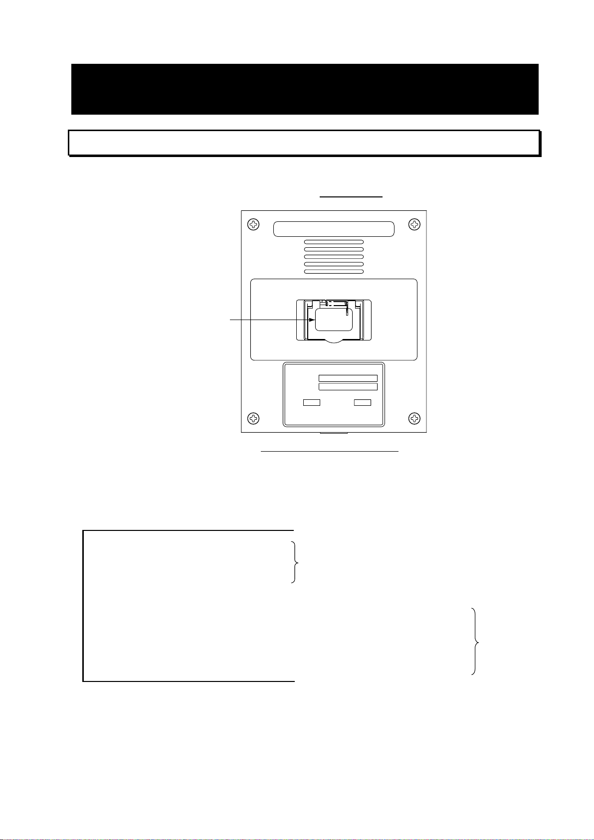
Telex Distress Alert Button IB-352 (Class 1 only)
1. Open the distress button cover on the IB-352.
2. Press and hold down the [DISTRESS] button
INMARSAT-B
TELEX DISTRESS ALERT BUTTON
Keep pressed for 6 s in case of DISTRESS.
The alert is transmitted with steady lighting.
six seconds
.
DISTRESS
button
Telex Distress Alert Button IB-352
DISTRESS
TELEX DISTRESS BUTTON
TYPE
SER.NO.
FURUNO ELECTRIC CO., LTD.
IB-352
COMPASS SAFE DISTANCE
mSTD
9-52 Ashihara-Cho, Nishinomiya
City, Japan
STEER
MADE IN JAPAN
0.60.8 m
The unit beeps intermittent ly and the red lamp on the button flashes. When the unit
beeps continuously and the red lamp lights, the distress message is sent to the LES.
Your outgoing message and message from the LES appear on the terminal unit and are
printed.
________________________
________________________
________________________
________________________
343112345 FURU X ------------------------------MARITIME
LAT 34 00 N, LONG 136 00 E ------------04 05 UTC, 24 MAY-----------------------------8--------------------------------------------------------180-----------------------------------------------------10--------------------------------------------------------
Message from designated LES
Your ship's answerback code
Position
Date
Nature of distress (8: Undesignate)
Ship's course
Ship's speed
These are
transmitted.
3. After the distress alert has been transmitted the line with the LES rem ains connected.
Send a message to the LES by direct keyboard input.
i
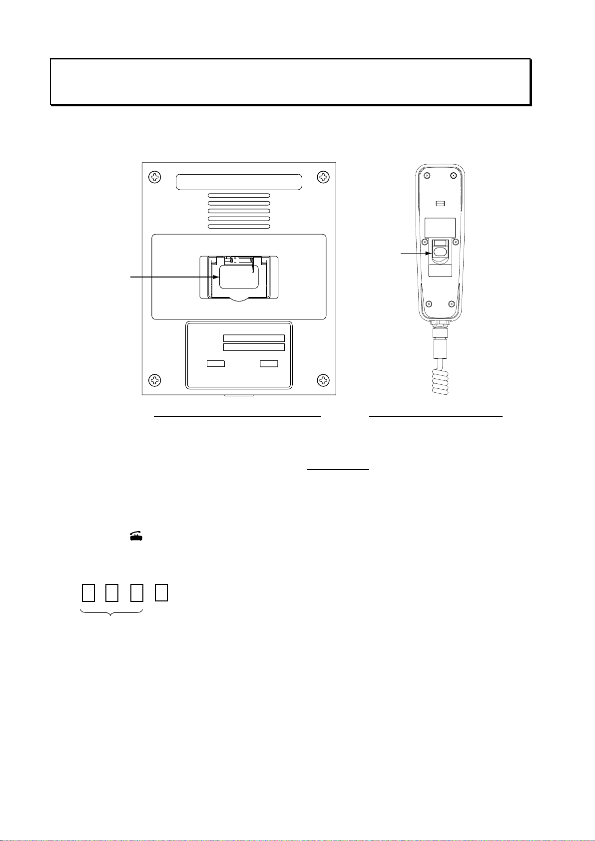
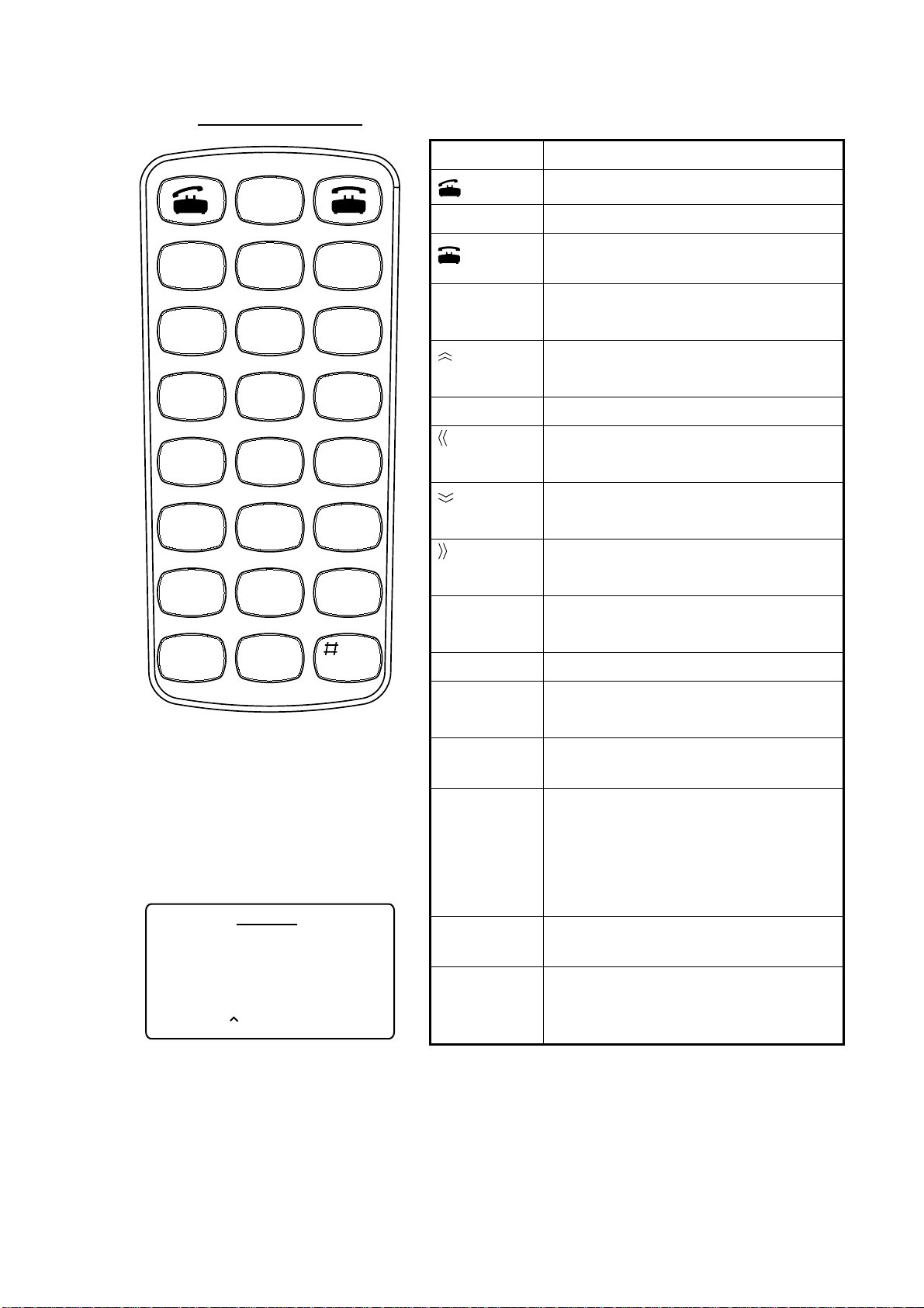
Telephone Distress Button IB-362, Handset IB-882-362 (Class 1, Class 2)
The [DISTRESS] button is incorporated in the hanger of the Handset IB-882-362 or in the
Telephone Distress Alert Button IB-362 in t he case of the Handset IB-882.
INMARSAT-B
TELEPHONE DISTRESS ALERT BUTTON
BRACKET UNIT
TYPE RB-2721B/362
SER.NO.
COMPASS SAFE DISTANCE
m1.402.05 mSTD
STEER
FURUNO ELECTRIC CO., LTD.
9-52 Ashihara-Cho,Nishinomiya
MADE IN JAPAN
City,Japan
DISTRESS
Keep pressed for 6 s
in case of DISTRESS.
The alert is transmitted
with steady lighting.
DISTRESS
button
Keep pressed for 6 s in case of DISTRESS.
The alert is transmitted with steady lighting.
DISTRESS
DISTRESS
button
TELEPHONE DISTRESS BUTTON
TYPE
SER.NO.
FURUNO ELECTRIC CO., LTD.
IB-362
COMPASS SAFE DISTANCE
mSTD
9-52 Ashihara-Cho, Nishinomiya
City, Japan
STEER
MADE IN JAPAN
0.60.8 m
Telephone Distress Alert Button IB-362 Hanger of Handset IB-882-362
1. Pick up the handset.
2. Open the distress button cover.
3. Press and hold do wn the [DISTRESS] button
six seconds
.
The distress alert device beeps intermittently and the red lamp on the button flashes.
When the device beeps continuously and the red lamp lights, the priority of the handset is
set to “Distress.”
4. Press the [
] key on the handset.
5. Dial an LES, referring to Appendix B, and press the [#] key as below. (The beep stops
when you are connected with the LES.)
#
LES No.
6. Commence communication with LES, giving your ship’s name, nature of distress,
assistance needed and description of your vessel.
ii
SAFETY INSTRUCTIONS
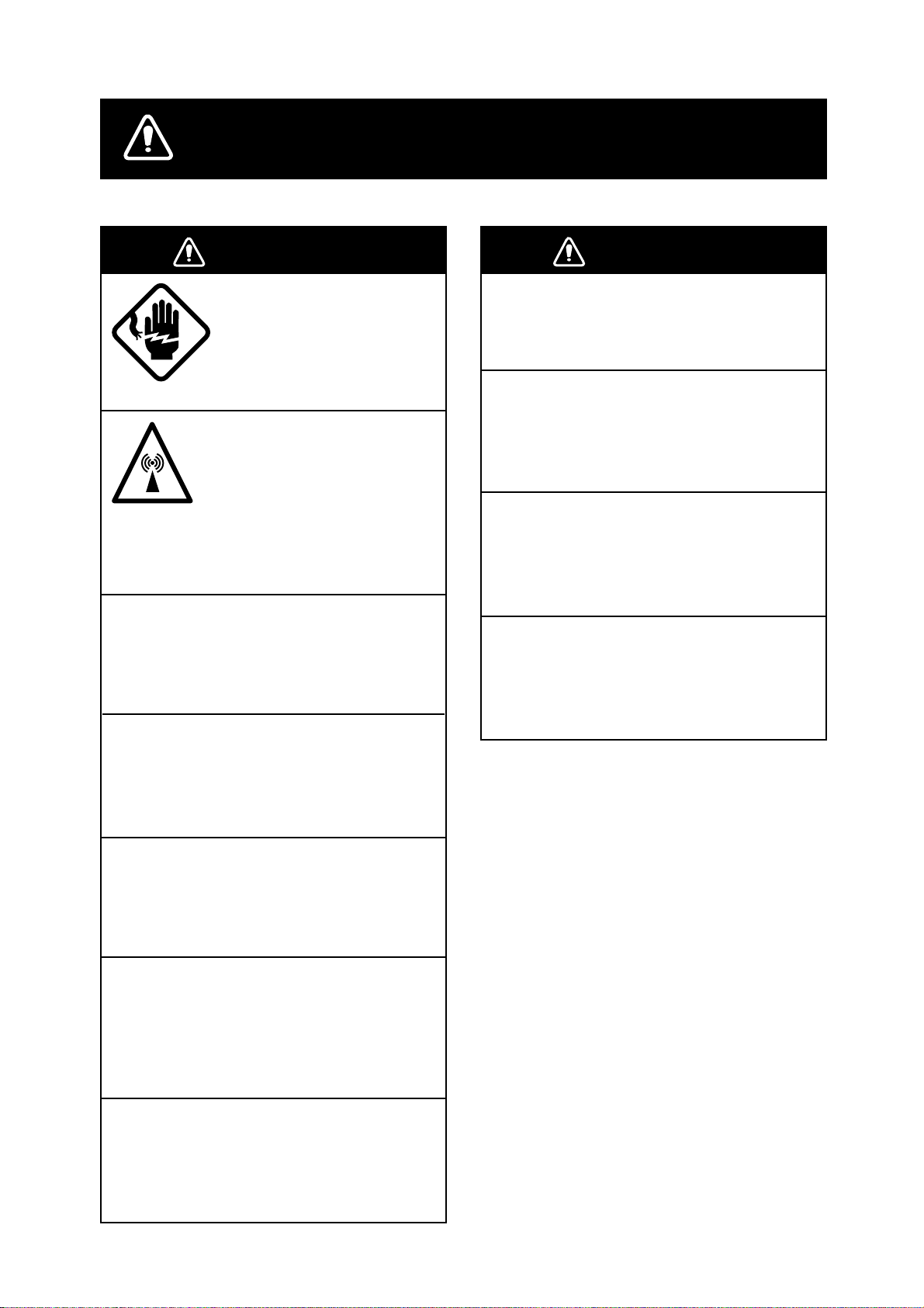
WARNING
ELECTRICAL SHOCK HAZARD
Do not open the equipment.
Only qualified personnel
should work inside the
equipment.
Do not approach the radome
closer than 6 meters when
it is transmitting.
The radome emits radio waves
which can be harmful to the
human body, particularly
the eyes.
Leave the equipment powered while
underway.
Distress cannot be communicated unless
the equipment is powered.
Wait at least 30 minutes after turning off
the power before entering the radome.
WARNING
Do not operate the equipment with wet
hands.
Electrical shock can result.
Keep heater away from equipment.
Heat can alter equipment shape and melt
the power cord, which can cause fire or
electrical shock.
Any repair work must be done by a
licensed radio technician.
Improper repair work can cause electrical
shock or fire.
Use the proper fuse.
Fuse rating is shown on the equipment.
Use of a wrong fuse can result in damage
to the equipment.
The gyro motor rotates for some time after
the power is turned off.
Do not disassemble or modify the
equipment.
Fire, electrical shock or serious injury can
result.
Turn off the power immediately if water
leaks into the equipment or the equipment is emitting smoke or fire.
Continued use of the equipment can cause
fire or electrical shock.
Do not place liquid-filled containers on
the top of the equipment.
Fire or electrical shock can result if a liquid
spills into the equipment.
iii
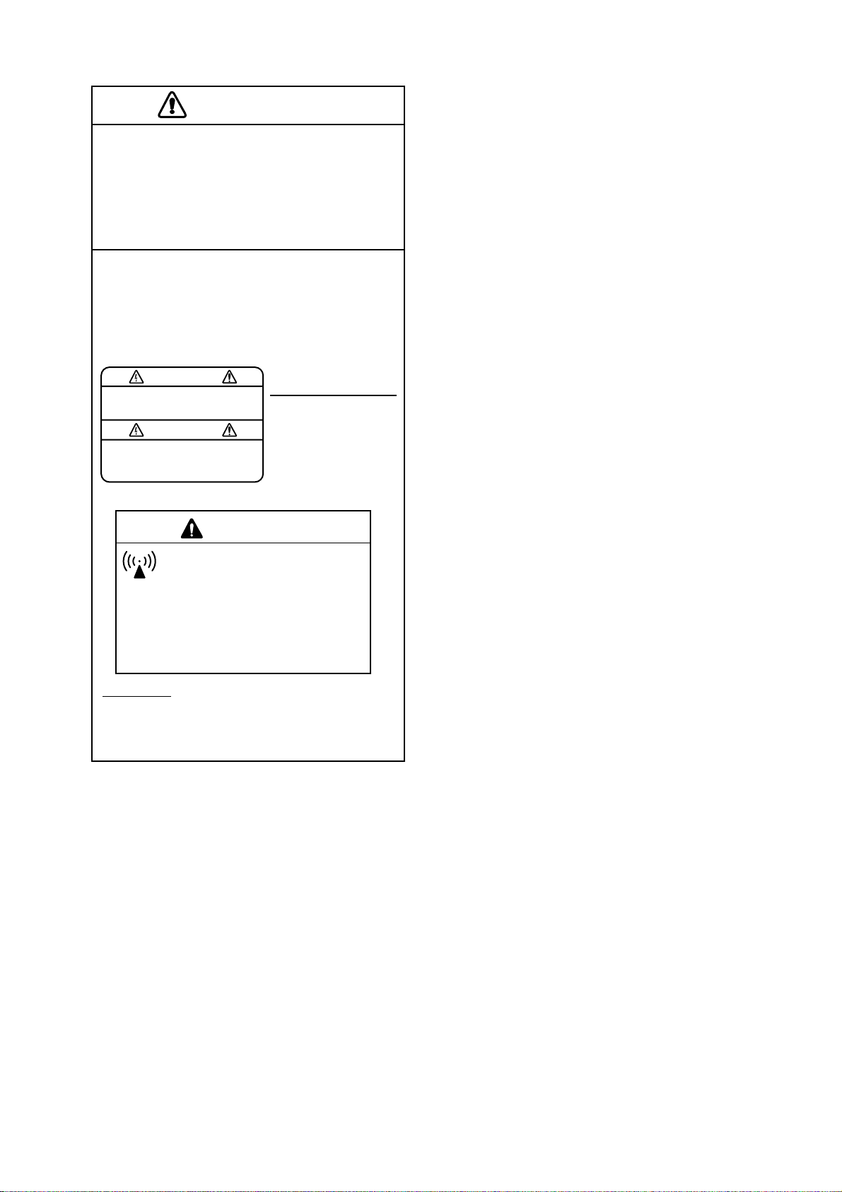
CAUTION
Do not use the equipment for other than
its intended purpose.
Use of the equipment as a stepping stool,
for example, can result in personal injury
or equipment damage.
A warning label is attached to the
terminal, communication and antenna
units. Do not remove any label. If a label
is missing or damaged, contact a
FURUNO agent or dealer.
WARNING
To avoid electrical shock, do not
remove cover. No user-serviceable
parts inside.
Terminal, Communication
Unit
Name: Warning Label (1)
Type: 86-003-1011-0
Code No.: 100-236-230
WARNING
Hazardous microwave radiation.
Can cause severe injury or illness.
Keep at least 6m from INMARSAT-B radome.
Radiation Level
100W/m
25W/m
10W/m
Antenna Unit
Name: Radiation Warning Label
Type:
16-007-7902-0
Code No.:
100-216-340
2
2
2
At
1.0m
4.0m
6.0m
iv

TABLE OF CONTENTS
FOREWORD .........................................................................................................x
SYSTEM CONFIGURATION, PROGRAM NUMBERS........................................xi
1. INMARSAT-B SYSTEM ................................................................................1-1
1.1 What is Inmarsat?......................................................................................................1-1
1.2 Geostationary Satellites.............................................................................................1-1
1.3 Service Area ..............................................................................................................1-2
1.4 System Bodies...........................................................................................................1-3
1.5 Inmarsat-B Services...................................................................................................1-4
1.6 Comparison of Inmarsat Systems ..............................................................................1-4
2. SETTING UP .................................................................................................2-1
2.1 Controls.....................................................................................................................2-1
2.1.1 Terminal unit (Class 1 only).............................................................................2-1
2.1.2 Handset ..........................................................................................................2-2
2.2 Turning On the Power................................................................................................2-4
2.3 Menu Operational Overview .......................................................................................2-7
2.3.1 Terminal unit (Class 1 only).............................................................................2-7
2.3.2 Handset ..........................................................................................................2-8
2.4 Adjusting Display Brilliance........................................................................................2-9
2.4.1 Terminal unit (Class 1 only).............................................................................2-9
2.4.2 Handset ..........................................................................................................2-9
2.5 Registering the Password at the Handset................................................................2-10
2.6 Distress Message Setup (Class 1 only)....................................................................2-11
2.7 Choosing Where (LES) to Transmit Own Ship’s Distress Signal..............................2-14
2.8 Setting Up the Handset, Communication Unit..........................................................2-15
2.8.1 Selecting ocean region to use.......................................................................2-15
2.8.2 Choosing navarea(s) from which to receive Inmarsat services......................2-15
2.9 Manual Entry of Position..........................................................................................2-17
2.10 Manual Entry of Heading..........................................................................................2-18
2.11 Setting Date, Time...................................................................................................2-19
2.12 Terminal Unit Setup (Class 1 only)...........................................................................2-21
2.13 Editor Setup (Class 1 only) ......................................................................................2-22
2.14 Terminal Unit Display Color......................................................................................2-23
3. TELEX COMMUNICATIONS (Class 1 only)................................................3-1
3.1 Before Beginning Communications............................................................................3-1
3.1.1 Overview.........................................................................................................3-1
3.1.2 Registering, deleting LES................................................................................3-2
3.1.3 Registering, deleting stations..........................................................................3-3
3.1.4 Creating me ssage files....................................................................................3-4
3.1.5 Saving message files......................................................................................3-7
3.1.6 Opening message files....................................................................................3-8
3.1.7 Other File menu operations.............................................................................3-9
v

3.2 Automatic Te lex.......................................................................................................3-11
3.2.1 Automatic telex procedure overview..............................................................3-11
3.2.2 Detailed procedure........................................................................................ 3-12
3.3 Manual Telex...........................................................................................................3-14
3.3.1 Manual telex procedure overview..................................................................3-14
3.3.2 Detailed procedure........................................................................................ 3-14
3.4 Programmed Te lex ..................................................................................................3-18
3.4.1 Programmed telex overview.......................................................................... 3-18
3.4.2 Programming ................................................................................................3-19
3.4.3 Deleting programs.........................................................................................3-21
3.5 Receiving .................................................................................................................3-22
3.5.1 Receiving ro u ti n e me ssa g es.........................................................................3-22
3.5.2 Receiving confidential messages..................................................................3-23
3.6 Polling......................................................................................................................3-25
3.6.1 Polling procedure overview...........................................................................3-25
3.6.2 Polling setup .................................................................................................3-26
3.6.3 Transmitting the polling command.................................................................3-27
3.7 Distress Communications ........................................................................................3-28
3.7.1 Transmitting the distress alert.......................................................................3-28
3.7.2 Distress commun ications..............................................................................3-28
3.7.3 Distress alert transmission when you are not pressed for time......................3-28
3.8 Editing, Printing Text................................................................................................3-29
3.8.1 Displaying the Edit menu ..............................................................................3-29
3.8.2 Cutting, pasting text......................................................................................3-29
3.8.3 Copying and pasting text...............................................................................3-30
3.8.4 Other edit features........................................................................................3-30
3.8.5 Printing messages ........................................................................................3-33
3.9 Main Menu Description ............................................................................................3-35
3.10 Keyboard Shortcuts .................................................................................................3-39
3.10.1 [Alt] key.........................................................................................................3-39
3.10.2 [Ctrl] key........................................................................................................3-40
4. HANDSET COMMUNICATIONS...................................................................4-1
4.1 Standby Display.........................................................................................................4-1
4.2 Display Markers; How to Enter Data, Symbols...........................................................4-2
4.3 Calling........................................................................................................................4-3
4.3.1 General calling procedure...............................................................................4-3
4.3.2 Dialing prefix number......................................................................................4-6
4.3.3 Calling when personal ID is in effect................................................................4-8
4.4 Redialing....................................................................................................................4-9
4.5 Receiving .................................................................................................................4-10
4.5.1 Call received at handset................................................................................4-10
4.5.2 Call received at location other than handset..................................................4-10
4.5.3 Receiving distress, safety, urgent call...........................................................4-11
4.6 Holding, Forwarding a Call.......................................................................................4-12
4.6.1 Holding a call ................................................................................................ 4-12
4.6.2 Forwarding a call...........................................................................................4-12
vi

4.7 Intercom.............................................................................................................................. 4-13
4.7.1 Using the intercom.................................................................................................. 4-13
4.7.2 When receiving a call during intercom use ............................................................ 4-13
4.8 Abbreviated Dialing ............................................................................................................ 4-14
4.8.1 Programming abbreviated dialing numbers ........................................................... 4-14
4.8.2 Dialing abbreviated dialing number........................................................................ 4-16
4.8.3 Deleting abbreviated dialing numbers.................................................................... 4-17
4.8.4 Editing abbreviated dialing numbers...................................................................... 4-17
4.9 Urgent/Safety Communications ......................................................................................... 4-18
4.10 Distress Communications................................................................................................... 4-19
4.11 Menu Operations................................................................................................................ 4-20
4.11.1 User and Administration modes............................................................................. 4-20
4.11.2 Changing operation mode...................................................................................... 4-21
4.11.3 Changing User mode format.................................................................................. 4-21
4.11.4 How to open a menu when using the Administration mode................................... 4-22
4.11.5 Customizing the User menu................................................................................... 4-22
4.12 Communications Log.......................................................................................................... 4-24
4.13 Personal ID Number (PIN) ................................................................................................. 4-25
4.13.1 Entering PIN ........................................................................................................... 4-25
4.13.2 Enabling PIN usage................................................................................................ 4-26
4.13.3 Editing, printing the PIN list .................................................................................... 4-26
4.14 Toll Charges........................................................................................................................ 4-28
4.14.1 Setting the toll charge calculator ............................................................................ 4-28
4.14.2 Displaying toll charges............................................................................................ 4-29
4.14.3 Clearing toll charges data....................................................................................... 4-29
4.15 Forced Clear....................................................................................................................... 4-30
4.16 Optional Telephone/Fax Setup .......................................................................................... 4-31
4.16.1 Restricting telephone call length ............................................................................ 4-31
4.16.2 Setting telephone/fax for answer only.................................................................... 4-33
4.16.3 Setting telephone as “credit call usage” telephone................................................ 4-34
4.16.4 Echo canceller ........................................................................................................ 4-35
4.17 Printing................................................................................................................................ 4-36
4.17.1 How to print............................................................................................................. 4-36
4.17.2 Printout examples................................................................................................... 4-37
5. OPTIONAL EQUIPMENT ............................................................................................ 5-1
5.1 Telephone FC755D1............................................................................................................ 5-1
5.1.1 Telephone communication overview........................................................................ 5-1
5.1.2 Telephone controls................................................................................................... 5-2
5.1.3 Calling....................................................................................................................... 5-4
5.1.4 Receiving.................................................................................................................. 5-5
5.1.5 Intercom.................................................................................................................... 5-6
5.1.6 Holding a call ............................................................................................................ 5-6
5.1.7 Forwarding a call ...................................................................................................... 5-6
5.1.8 Abbreviated dialing ................................................................................................... 5-7
5.2 Facsimile FAX-8070P/FAX-2850......................................................................................... 5-9
5.2.1 Dialing subscribers ................................................................................................... 5-9
vii

5.3 Incoming Indicator IB-372........................................................................................5-11
5.3.1 Ringer fo rmat................................................................................................5-11
5.3.2 Automatic alarm shut off ...............................................................................5-12
5.3.3 Disabling the buzzer......................................................................................5-12
6. 9.6k DATA COMMUNICATIONS ...................................................................6-1
6.1 General......................................................................................................................6-1
6.1.1 Main features..................................................................................................6-2
6.1.2 Terminology.....................................................................................................6-2
6.2 About Data Communications .....................................................................................6-3
6.3 Considerations...........................................................................................................6-5
6.4 Preparations for Communi cati ons..............................................................................6-6
6.4.1 Procedure for initial setup................................................................................6-6
6.4.2 Setting the communication parameters...........................................................6-6
6.4.3 Setting up the communication software........................................................... 6-9
6.5 Starting and Finishing a Communication..................................................................6-10
6.5.1 Changing the sea area..................................................................................6-10
6.5.2 Changing the communication parameters.....................................................6-10
6.5.3 Outgoing calls...............................................................................................6-10
6.5.4 Incoming calls...............................................................................................6-10
6.5.5 Finishing a communication............................................................................6-11
6.6 Viewing the State of MES........................................................................................6-12
6.7 AT Commands.........................................................................................................6-13
6.7.1 What are the AT commands?........................................................................6-13
6.7.2 Basic A T commands......................................................................................6-14
6.7.3 Extended A T commands ...............................................................................6-18
6.8 S Registers..............................................................................................................6-25
6.9 Result Codes...........................................................................................................6-26
6.10 +WQ Cause Codes..................................................................................................6-27
6.11 +WQ Extended Error Codes....................................................................................6-27
7. HSD COMMUNICATIONS.............................................................................7-1
7.1 HSD Setup.................................................................................................................7-2
7.2 Automatic HSD Call...................................................................................................7-5
7.2.1 How to make an automatic HSD call...............................................................7-5
7.2.2 How to clear an automatic HSD call................................................................7-5
7.3 Manual HSD Call .......................................................................................................7-6
7.3.1 Manual HSD call.............................................................................................7-6
7.3.2 Manually clearing HSD connection..................................................................7-7
7.4 Receiving an HSD Call...............................................................................................7-8
7.5 V.25bis Commands and Indications........................................................................... 7-9
7.6 Usage Hints.............................................................................................................7-10
8. MAINTENANCE, TROUBLESHOOTING......................................................8-1
8.1 Maintenance..............................................................................................................8-1
8.1.1 Checks............................................................................................................8-1
8.1.2 Replacement of battery...................................................................................8-2
8.1.3 Replaceme n t of fuse.......................................................................................8-2
8.2 Checking Equipment Status.......................................................................................8-3
viii

8.3 Tests..................................................................................................................................... 8-5
8.3.1 Displaying the test menu .......................................................................................... 8-5
8.3.2 Program version no. ................................................................................................. 8-5
8.3.3 Memory test.............................................................................................................. 8-6
8.3.4 Distress test.............................................................................................................. 8-7
8.4 Restoring Default Settings.................................................................................................... 8-8
8.5 Antenna Orientation (for technicians)................................................................................... 8-9
8.6 Error Messages at the Terminal Unit ................................................................................. 8-10
8.6.1 Call failure............................................................................................................... 8-10
8.6.2 Antenna trouble ...................................................................................................... 8-12
8.6.3 Printer trouble ......................................................................................................... 8-12
8.6.4 Communication unit trouble (internal).................................................................... 8-13
8.7 When the Power Cannot be Turned On............................................................................. 8-14
APPENDIX A Menu Overview..........................................................................................A-1
Handset........................................................................................................................................A-1
Terminal Unit.................................................................................................................................A-4
APPENDIX B Telephone, Telex Country Code Lists......................................................B-1
Appendix C LES Access Code List................................................................................C-1
Appendix D Telex Abbreviations, International Telegraphy Alphabet.........................D-1
APPENDIX E Digital Interface (IEC 61162-2)..................................................................E-1
APPENDIX F Parts Location, Parts List .........................................................................F-1
SPECIFICATIONS.......................................................................................................... SP-1
INDEX
Declaration of conformity
ix

FOREWORD
A Word to the Owner of the FURUNO FELCOM 82A/82B
Congratulations on your choice of the FURUNO FELCOM 82A (Class 1),
FELCOM 82B (Class 2) Inmarsat-B Mobile Earth Station. We are confident you
will see why the FURUNO name has becom e synonymous with quality and
reliability.
For over 50 years FURUNO Electric Company has enjoyed an enviable
reputation for quality marine electronics equipment. This dedication to
excellence is furthered by our extensive global network of agents and dealers.
This equipment is designed and constructed t o meet the rigorous demands of
the marine environment. Ho wever, no machine can perform its intended function
unless operated and maintained properly. Please carefully read and follow the
recommended procedures for operation and maintenance.
We would appreciate hearing from you, the end-user, about whether we are
achieving our purposes. Thank you for considering and purchasing FURUNO
equipment.
Features
The FELCOM 82A/82B mainly consists of an antenna unit, communication unit
and a handset. FELCOM 82A is additionally equipped with a terminal unit. The
FELCOM 82A provides telephone, facsimile, telex and data services. The
FELCOM 82B provides the same services as the FELCOM 82A excluding telex.
The main features of the FELCOM 82A/82B are
•
•
•
•
•
•
•
•
•
•
•
Conforms to the following standards: IMO A. 808(19), IMO A. 694(17), IEC
61097-10 (1999), IEC 60945 (1996), I E C 61162-1 (2000)
Compact handset functions as main telephone
Automatic telephone/fax switching
Toll charges calculator
Personal ID to monitor telephone, han dset and fax usage
Internal gyro interface
9.6 kbps data communication
High speed fax communication
Automatic input and update of ship’s position and gyr ocompass heading with
position and heading data inputs
Non-rewind antenna
HSD communication function provided as standard.
x
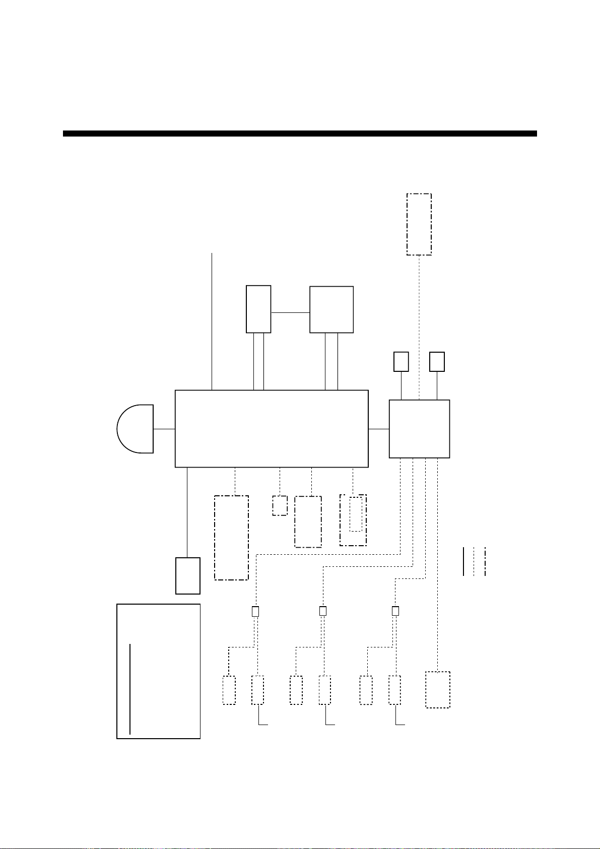
SYSTEM CONFIGURATION, PROGRAM NUMBERS
ANTENNA
UNIT
IB-182
Ship’s mains
100-115/
220-230 VAC
1 phase, 50/60 Hz
UNIT
IB-282
COMMUNICATION
9.6K DATA
PP-510
PRINTER
#2
GYROCOMPASS
(FELCOM 82A only)
DGPS
UNIT
IB-582
TERMINAL
HSD
DECODER
PC
(FELCOM 82A only)
HSD IF
NAVIGATOR
TELEX DISTRESS ALERT BUTTON IB-352
(FELCOM 82A only)
BOX
IB-313
JUNCTION
#1 = For use with Handset IB-882.
#2 = Cable between PRINTER port
(communication unit) and PARALLEL
TELEPHONE DISTRESS BUTTON IB-362 #1
for FELCOM 82B only
Standard supply
Option
Local supply
PC
(PC-AT Converter)
HANDSET
IB-882/IB-882-362
MJ-2S
FACSIMILE FAX-2850/FAX-8070P
INCOMING INDICATOR IB-372
Max. 3 units
100 VAC
TELEPHONE FC755D1
165-0146-004 (2001/4)
165-0145-008 (2002/4)
165-0152-002 (2001/7)
165-0144-001 (2000/12)
165-0142-004 2001/2)
165-0143-002 2001/1)
DEMOD
PROGRAM VERSION NO.
MAIN
TERM
HANDSET
DECODE
SYNC
MJ-2S
FACSIMILE FAX-2850/FAX-8070P
100 VAC
TELEPHONE FC755D1
MJ-2S
TELEPHONE FC755D1
FACSIMILE FAX-2850/FAX-8070P
100 VAC
xi

This page is intentionally left blank .

1. INMARSAT-B SYSTEM
1.1 What is Inmarsat?
The International Maritime Satellite Organization (Inmarsat), founded in 1979, is
the international governing body for maritime satellite communication. Its purpose
is to provide global communications for ships, land mobile and aircraft, using
satellites to overcome the problems that exist with conventional radio
communications.
The Inmarsat system is made up of three major components: the space segm ent
provided by Inmarsat, the Land Earth Stations (LES) provided by Inmarsat
signatories, and Mobile Earth Stations (MES). The Operat ion Control Center
(OCC), located at Inmarsat headquarters in London, controls t he overall system.
1.2 Geostationary Satellites
The type of satellites used for maritime communication are geost at ionary
satellites. Four satellites, one for each of f our ocean regions, are placed in nearly
36,000 km-high 24-hour circular orbits rotating in synchronous with the earth,
providing mobile-to-land, land-to-mobile, and mobile-to-mobile communications.
The satellites remain fixed over a given place on the eart h's equator, so an
Inmarsat subscriber is always within coverage of a satellite.
Geostationary satellite
Earth
Geostationary satellites of the Inmarsat system
(35,860 km above Equator)
Speed: 11,070 km/h
Revolution: 23 hrs 56 min
72,752 km
35,860 km
1-1
1. INMAR SAT-B SYSTEM
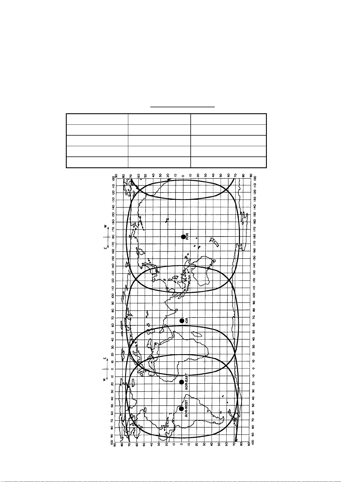
1.3 Service Area
The Inmarsat system divides the world into four regions and each regi on is
covered by its own satellite. The regions are Atlantic Ocean Region-East (AORE), Atlantic Ocean Region West (AOR-W), Pacific Ocean Region (POR), and
Indian Ocean Region (IOR). The reason for two regions in t he Atlantic Ocean is
to solve the coverage gap problem there.
Region Satellite Satellite position
AOR-West Inmarsat-3, F4 54.0°W
AOR-East Inmarsat-3, F2 15.5°W
IOR Inmarsat-3, F1 64.0°E
POR Inmarsat-3, F3 178.0°E
Inmarsat satellite data
1-2
Coverage area
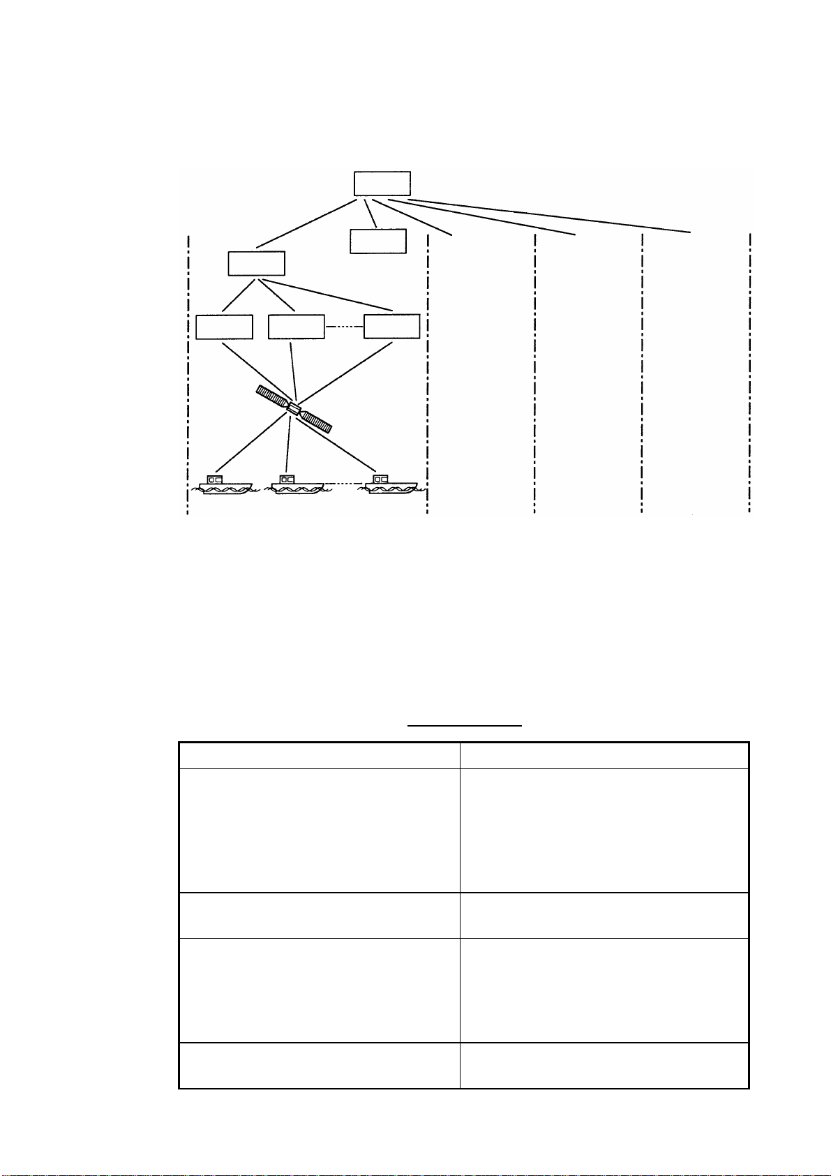
1.4 System Bodies
The Inmarsat system consists of the bodies shown in the f igure below.
NCS
1. INMAR SAT-B SYSTEM
OCC
SCC
LES LES LES
Satellite
MES
AOR-West AOR-East IOR POR
OCC: Operation Control Center
SCC: Satellite Control Center
NCS: Network Coordination Station
MES: Mobile Earth Station
LES: Land Earth Station
Same as left
Same as left
Same as left
Inmarsat system bodies
The function of each body in the Inmarsat system is as shown in the table below.
Inmarsat bodies
Body Function
Operation Control Center (OCC) The OCC is the nerve center of the
system and is located at the Inmarsat’s
headquarters in London. The OCC
provides continuous, round-the-clock
cooordination for all functions in the
Inmarsat system.
Satellite Control Centers (SCC)
The SCCs main function is to correct
satellite rotation error.
Network Coordination Stations (NCS)
Each region has an NCS. The NCS
controls the lines of communication and
broacasts information such as
navigational warnings, weather reports
and news.
Mobile Earth Stations (MES)
Mobile Inmarsat-B stations including
aircraft.
1-3

1. INMAR SAT-B SYSTEM
1.5 Inmarsat-B Services
The Inmarsat-B maritime satellite communication system provides digit al
telephone (voice), facsimile, telex and data (9600 kbps) an d HSD services. Use
of the latest digital technology means lower toll charges than in Inmarsat-A, since
high output power satellites are not required and data is transmitted at high
speed.
1.6 Comparison of Inmarsat Systems
Inmarsat provides worldwide communication services f or bot h maritime and land
subscribers, and consists of four systems, A, B, C, M and Mini-M. The following
table shows the services available with each system.
Comparison of Inmarsat systems
Service Inmarsat-A Inmarsat-B Inmarsat-C Inmarsat-M Inmarsat Mini-M
Voice YES YES NO YES YES
Facsimile YES YES NO YES YES
Telex YES YES YES NO NO
Data YES YES YES YES YES
HSD YES YES NO NO NO
1-4

2. SETTING UP
2.1 Controls
2.1.1 Terminal unit (Class 1 only)
Esc
~
`
Tab
Caps Lock
Fn
F1
F2 F3
2
1
QWERTYUIOP
ASDF GHJ KL:+;"
ZXCVBNM<> ?/
Ctrl Alt
F4
F5 F6
%
$#@!
345
F7
^&
F8
F9 F10
*
67890 - =
456
123
Num
Lock
(
9*87
0Shift
,
Alt
Prt Sc
SysRq
.
Ctrl
Scroll
Lock
_+)
{}\|
[
/
Home
'
Pause
Break
]
Shift
End PgDn
Insert Delete
Backspace
Enter
Keyboard
Key description
Esc Cancels key input and returns to previous display screen.
F1-F10 These keys select menus (F1-F4) and telex functions (F5-F7,
F9-F10).
PgUp
Backspace Deletes the character to the left of the cursor.
Insert Works the same as PASTE function.
Delete Deletes the character to the right of the cursor.
Home Moves the cursor to the top of a message being edited.
End Moves the cursor to the bottom of a message being edited.
PgUp Goes to the previous page of the editor screen.
PgDn Goes to the next page of the editor screen.
↑, ↓, ←, →
Control the cursor.
Enter Regist ers key input.
Shift Selects upper and lower case alphabet or numerics and symbols.
Press and hold down the key to get upper case letters. Note that
only upper case letters are used in telex.
2-1
2. SETTING UP
Alt Executes the shortcut key operation when combined with an
Space Bar Inserts a space. In addition, it displays file list , partial view of a file,
Caps Lock Turns upper case letter input on or off. Press this key while pressing
Tab Inserts horizontal tab characters. The number of tab characters the
Ctrl Executes the shortcut key operation when combined with an
alphabet key. See page 3-39.
etc. depending on menu.
and holding down the [Shift ] key to get all capital letters. CAPS
appears on the display when the keyboard is set for upper case
letter input.
key can insert per line of text can be programmed for two, four or
eight tabs on the Editor Setup menu.
alphabet key. See page 3-40.
Fn Combined with an arrow key, it scrolls the screen (
Num Lock Turns numeric input on or off. Note that you cannot enter some
Note: In telex, lower case, #, &, *, $ and % are not used. A full list of charact ers
usable in telex appears on page D-2.
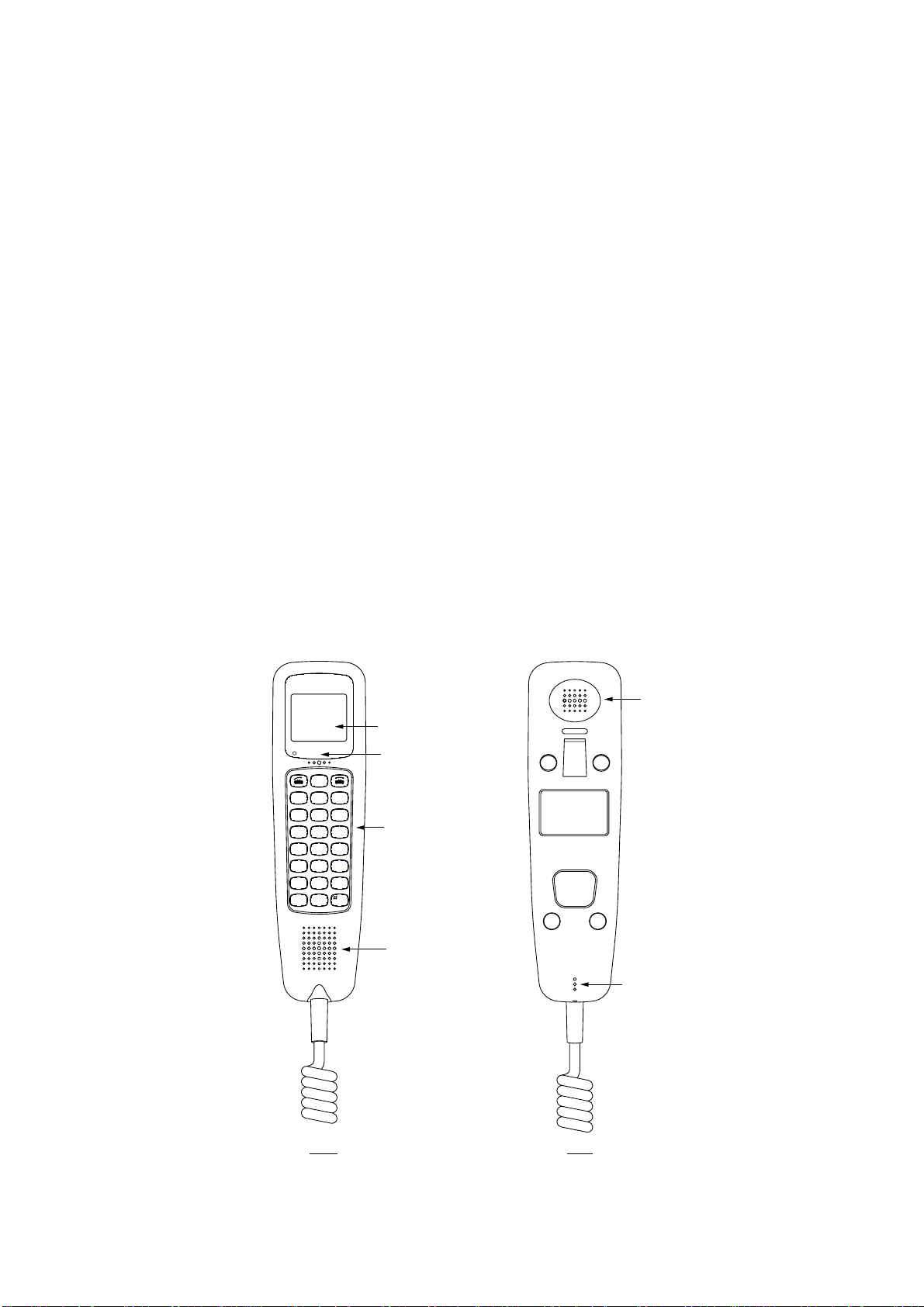
2.1.2 Handset
←, →
cursor (
).
alphabet when the Num LED is lit.
LCD
ALARM
HOLD
Print
<<
FUNC
Quit
GHI
PQRS
*
Mode Symb
REDIAL
<<
ABBR
Find
21
54
87
0
Inter
comm
<<
>>
DEL
Prty
3
DEF
ABC
6
MNOJKL
9
WXYZ
TUV
Ent
Alarm LED
(Flashes for
system
failure.)
Controls
(See next
page for
description.)
HANDSET UNIT
TYPE IB-882
SER.NO.
COMPASS SAFE DISTANCE
mSTD
2.05
FURUNO ELECTRIC CO., LTD.
9-52 Ashihara-Cho,Nishinomiya
MADE IN JAPAN
City,Japan
m1.40STEER
↑, ↓
Earpiece
) or shifts the
2-2
Loudspeaker
Microphone
Front Rear
Handset
Control description
REDIAL
2. SETTING UP
Control Function
Opens communication line (off hook.)
REDIAL Redials selected number.
HOLD
Print
<<
<<
FUNC
Quit
ABBR
Find
21
GHI
PQRS
*
Mode Symb
54
87
0
<<
ABC
TUV
Inter
comm
>>
DEL
Prty
3
DEF
6
MNOJKL
9
WXYZ
Ent
Disconnects communication line (on
hook).
HOLD Print • Holds connected party.
• Prints screen showing symbol “!”.
• Shifts cursor upward.
• Increases earpiece volume.
Intercomm Turns intercom on/off.
• Shifts cursor leftward.
• Selects menu option, parameter.
• Decreases earpiece volume.
• Shifts cursor downward.
• Shifts cursor rightward.
• Selects menu option, parameter.
FUNC Quit • Opens/closes menu.
• Returns to standby display.
ABBR Find Abbreviated dialing number f unctions
DEL Prty • Selects priority.
Symbols
[.] → [−] → [ _] → [*] → [#] → [(] →
[)] → [<] → [>] → [ [ ] → [ ] ] →
[{] → [}] → [=] → [/] → [!] → [?] →
[:] → [;] → [|] → ["] → [@] → [~] →
[+] → [,] → [ ] → [$] → [¥] → [%] → [']
• Deletes entry.
1 – 9 • Inputs corresponding alphabet or
numeric.
* Mode • Separator
• Alternately enables alphabet and
numeric input.
• Alternately selects East/West and
North/South and vice versa.
0 Symb
# Ent • End code
• Inputs “0” and symbols (see figure
at left).
• Terminates menu operation.
2-3
2. SETTING UP
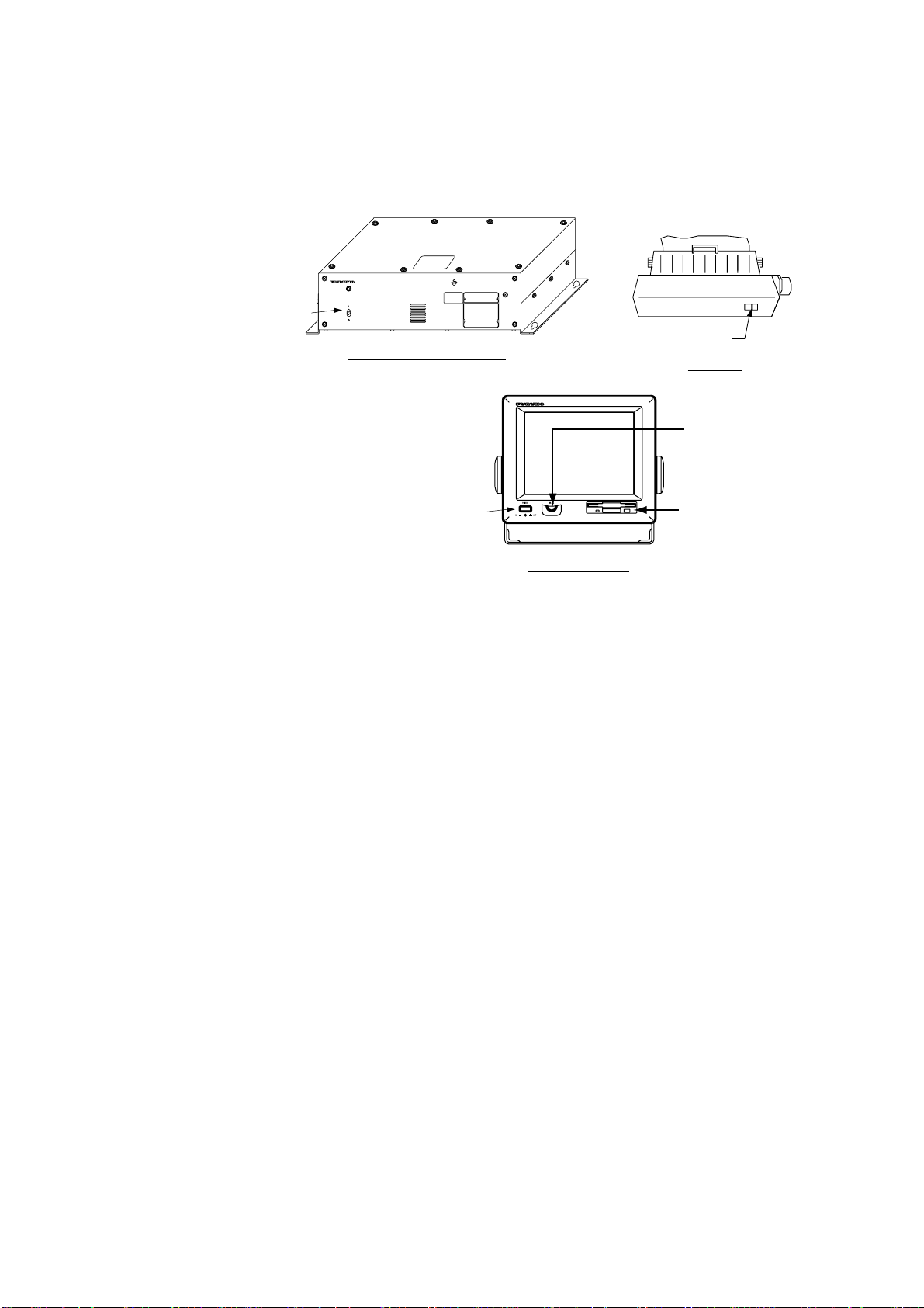
2.2 Turning On the Power
There is no particular order for turning on the units of t he system. The handset is
powered when the communication unit is turned on.
INMARSAT-B
MOBILE EARTH STATION
POWER Switch
FELCOM 82
POWER
ON
OFF
POWER Switch
Communication Unit
Printer
BRILL Control
POWER Switch
Floppy Disk
Drive
Terminal Unit
Location of power switches
When the communication unit is powered it supplies po wer to the handset and
the antenna unit. If a navigator and gyro are connected, the antenna unit is
automatically oriented towards the satellite select ed. Several minutes later the
satellite is “acquired” and the system goes into stand-by, awaiting
communcations. You can see the standby displays f or the terminal unit and
handset on the next page.
2-4
2. SETTING UP
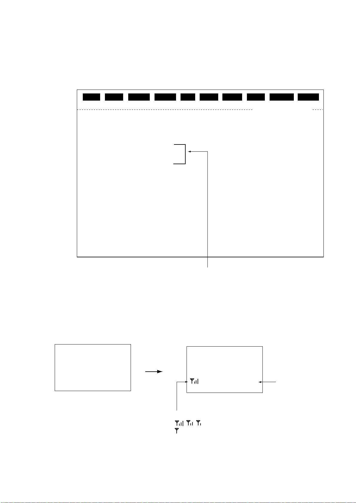
The standby display on the terminal unit appears abo ut ten seconds after turning
on the power. After turning on the power, you can begin communications when
the message “Ocean Region registration complete” appears. (The Channel
Status indication should show “SYNC” and the MES Status indication,
“Ready”. )This takes about five minutes.
File
Date
Time
Current Satellite
Channel Status
MES Status
Tx
Heading
Antenna Bearing
Antenna Azimuth
Antenna Elevation
Position
NAV DATA
GYRO DATA OK
Edit Telex Setup WRU HRIS BELL AlmRst Break
NMEA
2000-09-08
15:04(UTC)
POR
SYNC
Ready
OFF
270 DEG
209 DEG
119 DEG
30 DEG
LAT 34:00.00N
LON 135:00.00E
(00-09-08 15:04)
Tx EIRP Level
Tx RF Level
Rx C/N
Rx IF AGC Level
Rx SYN
Tx SYN
Antenna Status
El AXIS
Az AXIS
Cross EI AXIS
Rx Channel
Tx Channel
000
000
053
154
OK
OK
REMOTE
OK
OK
OK
11292
10000
The handset goes into standby about three seconds af ter the communications
unit is turned on. “Ready” appears when the handset is ready for communications.
When the power is supplied to the handset the displa y screen changes in the
following sequence.
FELCOM 82
Inmarsat-B
Mobile
Terminal
(c)FURUNO
Start-up display
Indications shown when
equipment is ready to communicate.
Standby display (terminal unit)
2000-08-29
12:34 UTC
Inmarsat-B
FELCOM 82
After 3 sec.
AORE Ready
Standby display
Signal strength
, , : Communications possible
: Signal strength too low to communicate.
Standby display (handset)
Ready for
communications
2-5

2. SETTING UP
When “Ready” is displayed on the terminal unit and ha ndset the following can be
done, with the equipm ent in the default setting.
Handset, telephone communications
•
When the handset rings, pick it up and press the [ ] key to communicate with
party.
•
When a telephone rings, pick up its receiver and communicate with party.
•
Dial subscriber’s number (LES, subscriber’s number or ship ID) to
communicate.
For handset operation see Chapter 4 and for telephone operation see Chapter 5.
Telex communications (Class 1 only)
•
Send a telex message automatically, provided that station and LES have been
registered in the equipment.
•
Receive and read a telex message.
For details see Chapter 3.
2-6
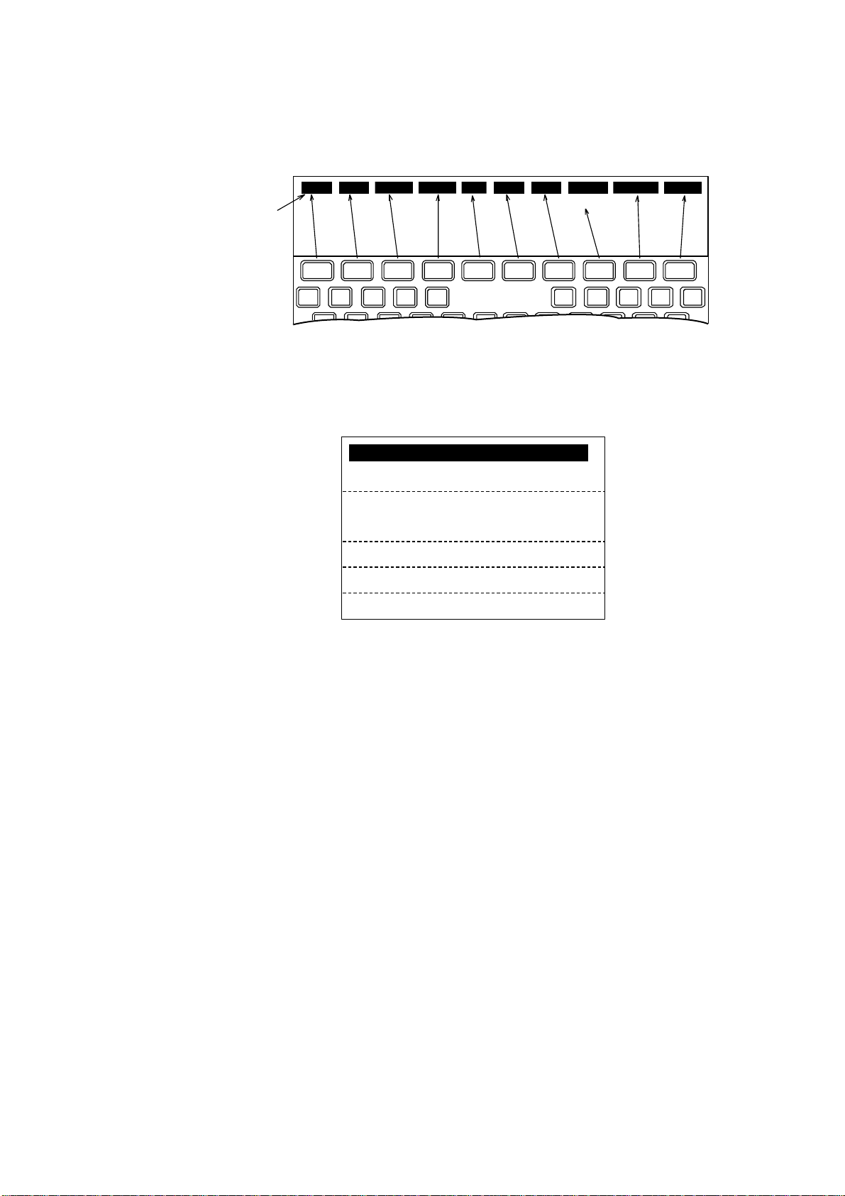
2.3 Menu Operational Overview
2.3.1 Terminal unit (Class 1 only)
File Edit Telex Setup WRU HRIS BELL AlmRst Break
Menu
2. SETTING UP
Not used)
F 1 F 2 F 3 F 4 F 5 F 6 F 7 F 8
Keyboard
F 9 F 10
Menu
1. To select a menu or function press the corresponding function key F1-F10 (F8
is not used). For example, press the [F4] key to display the Setup menu.
1: Station List
2: LES List
3: Terminal Setup
4: Editor Setup
5: Polling Configuration
6: Comm Unit Setup
7: Window Color
Setup menu
2. Key in desired menu number with the numeric keys. Alternat ely you may
select a menu by using the [↑] or [
↓
] key and then pressing the [Enter] key.
3. After setting option, press the [Enter] key.
4. Press the [Esc] key to return to the standby display.
2-7

2. SETTING UP
2.3.2 Handset
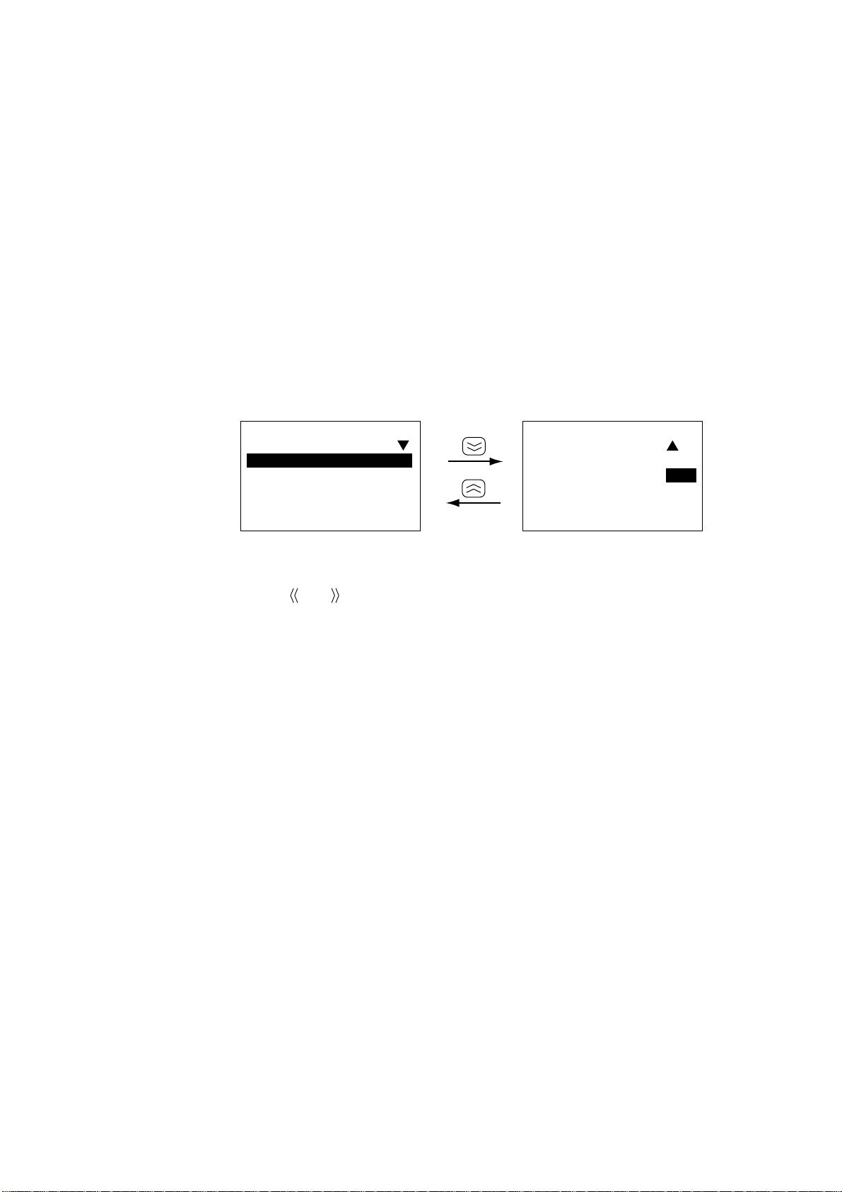
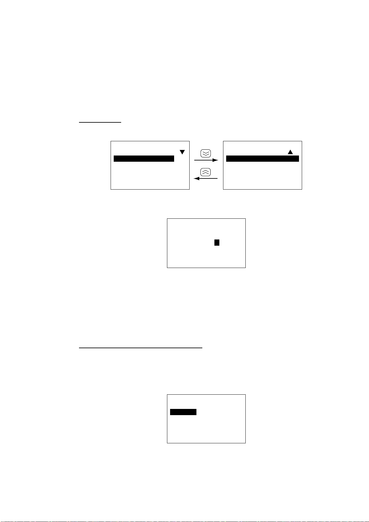
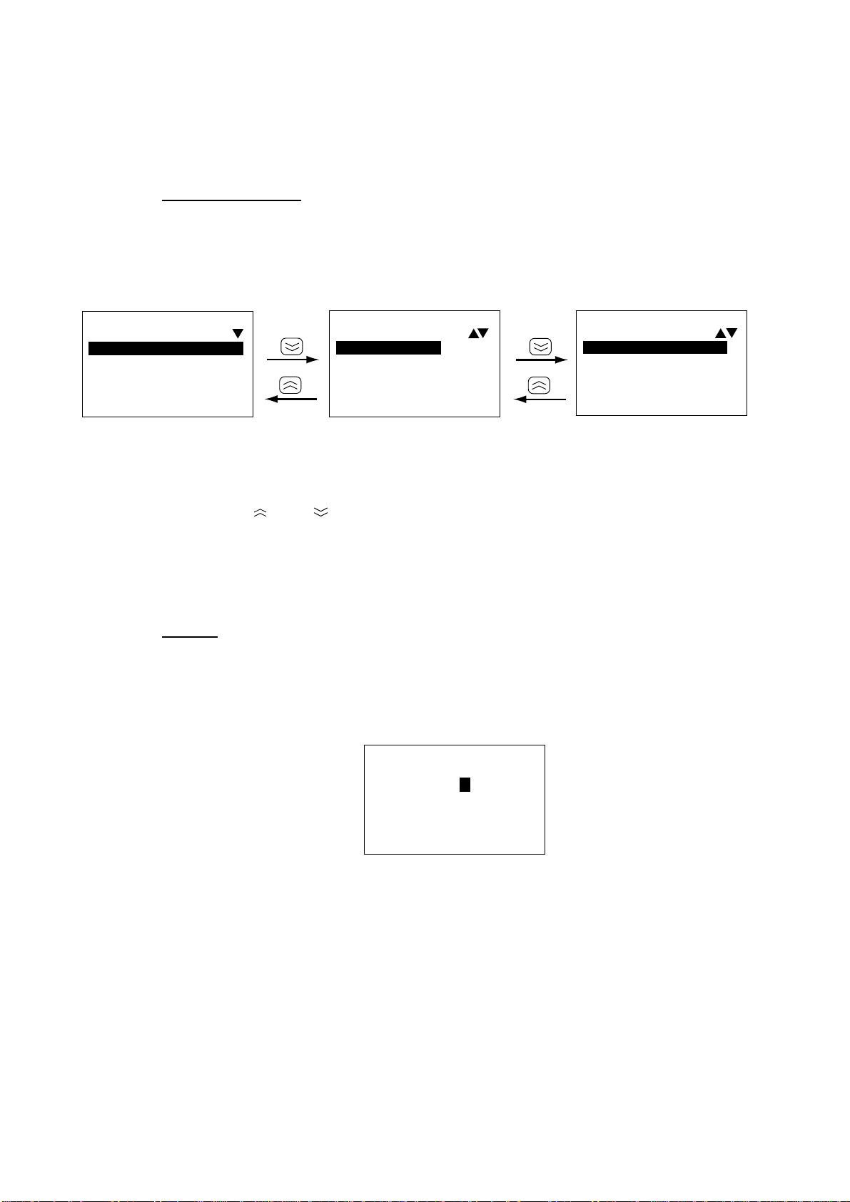
1. Press the [FUNC Quit] key to display the main menu. Not e that some menus
and displays show triangle(s) and/or a square at the top right-hand corner of
the display. See page 4-2 for their meanings.
Main Menu
Main Menu
5 Setup
6 MES
7 TELFAX
8 HSD*
Select:[Ent]
*Appears when HSD terminal's
OID/DID number is registered in
the handset.
Reserved for user
customization.
(See paragraph
4.11.5 on page
4-21 for further
details.)
1
2
3
4 Display
Select:[Ent]
Main menu (default menu)
2. Press appropriate numeric key to choose menu desired, or use the [
key to select menu desired and press the [Ent] key.
3. Press the [FUNC Quit] key several times to close the menu.
] or [ ]
2-8
2.4 Adjusting Display Brilliance
2.4.1 Terminal unit (Class 1 only)
Adjust the [BRILL] control to suit lighting conditions.
Note: If the terminal unit is turned off with brilliance set to minimum the display
will be black when the terminal unit is turned on again. Use the [BRILL]
control to adjust display brilliance.
2.4.2 Handset
The handset has facilities for adjustm ent of keyboard and LCD backlighting, LCD
contrast, key beep on/off, and call ring volume.
1. Press [FUNC Quit], [6] and [1] to display the Handset menu.
2. SETTING UP
61Handset
1 BackLight:3
2 IdleLight:1
3 LCDBright:5
4 BuzzerVol:7
Lo:[¬]Hi:[®]
61Handset
5 KeyClick :
OFF/ON
Lo:[¬]Hi:[®]
Handset menu
2. Press appropriate numeric key referring to above illustration to select item and
then press [
] or [ ] to set level. For IdleLight and KeyClick select ON or OFF.
BackLight: Sets backlighting for the LCD and keyboard. Setting range: 0 –
3, Default: 3. “0” provides no backlighting.
IdleLight: Turns backlighting for the LCD and keyboard on or off when
the handset is hung in the hanger. Settings: ON, OFF, Default:
OFF.
LCDBright: Adjusts brightness of LCD. Setting range 0 – 9, Default: 5. “0”
provides no brightness.
BuzzerVol: Adjust s volume of call ring. Setting range: 0– 9, Default: 7. “0”
turns off the call ring.
KeyClick: Turns key beep, which sounds for valid key input, on or off.
Settings: ON, OFF, Default: ON.
3. Press the [Ent] key.
4. Press the [FUNC Quit] key several times to close the menu and return to the
standby display.
2-9

2. SETTING UP
2.5 Registering the Password at the Handset
There are two handset menu modes: User and Administration. The User mode
provides only a simple menu. The Administration mode requires a password t o
open menus. When the system is powered the User mode is in effect.
The password set at the factory is 0000. In this setting you can go into the
Administration mode without a password. To require a pass word with the
Administration mode enter it as follo ws:
1. Press [FUNC Quit], [6] and [7] to display the Password input screen.
67Password
Old :
New :
Conf:
Enter:[Ent]
Password input screen
2. Key in 0 000. Password is shown with asterisks. If you are not using the
factory-set password (0000) enter current password.
3. Press the [ ] key to select the New field.
4. Enter password desired and press the [Ent] key. You may use any four
numerals for the password.
5. Press the [
] key to select Conf.
6. Enter password again and press the [Ent] key. The message “The password
is changed.” is displayed.
7. Press the [FUNC Quit] key to close the menu. (If the pass word entered is
invaild the message “Password error!” appears. Enter the password again.)
Store the password in a safe place. To clear the password, enter old password in
the Old field and 0000 in both the New and Conf fields.
Note: Normally the operational mode is t he “User m ode.” To change to the
Administration mode, do the following:
a) Press [FUNC Quit], [6] and [3] to display the Change Mode input screen.
63Change Mode
2-10
User→ Admin
Enter Passwd:
_ ___
Enter: [Ent]
b) Enter four digit-password and press the [Ent] key. Password entered is
shown with asterisks.
2.6 Distress Message Setup (Class 1 only)
The distress message, transmitted when the Telex Distress Alert Button IB-352 is
operated, may be set up from the handset and terminal unit.
This procedure is done from the Administration mode. See page 2-10 for how to
choose the Administration mode.
Ship’s name
1. Press [FUNC Quit], [5] and [8] to show the DMG menu.
2. SETTING UP
58DMG
1 Name :
2 Maritime:Y
3 Nature:8
4 Course:AUTO
Select:[Ent]
58DMG
5 Speed: AUTO
Select:[Ent]
DMG menu
2. Press the [1] key to show the Ship’s Name input screen.
58DMG
ALPH
Ship´s Name:
Enter:[Ent]
DMG menu, ship’s name input screen
3. Enter your ship’s abbreviated name (telex answerback code) in four
alphanumeric characters with the alphanumeric keys and press the [Ent] key.
If an invalid name is entered the m essage “Input Error. Invalid data.” appears
and three seconds later the main menu is shown.
4. Press the [FUNC Quit] key to close the menu.
Inmarsat station type (ship or shore)
The default station type is m aritime; do not change the setting.
1. Press [FUNC Quit], [5] and [8] to show the DMG menu.
2. Press the [2] key to select Maritime.
58DMG
Maritime:
1 Yes
2 No
Enter:[Ent]
DMG menu, station type entry
2-11
2. SETTING UP
3. Press the [1] key to select Y es for ship station, or press the [2] key to select No
4. Press the [Ent] key followed by the [FUNC Quit] key.
Nature of distress
Select nature of distress. The default nature of distress is Undesignate d.
1. Press [FUNC Quit], [5] and [8] to show the DMG menu.
2. Press the [3] key to select Nature.
for shore station.
58DMG
Nature:8
1 Fire/Explos
2 Flooding
3 Collision
4 Grounding
Enter:[Ent]
3. Press appropriate numeric key to select nature of distress (default: 8
Undesignated). You can toggle between the three nature of distress screens
with the [ ] and [ ] keys.
Note: The nature of distress is automatically restored to “Undesignated” after
4. Press the [Ent] key followed by the [FUNC Quit] key.
Course
Do this step when there is no course data due to position-fixing equipment failure.
1. Press [FUNC Quit], [5] and [8] to show the DMG menu.
2. Press the [4] key to select Course.
one hour.
58DMG
Nature:8
5 Listing
6 Sinking
7 Disable&Adr
8 Undesignate
Enter:[Ent]
DMG menu, nature of distress options
58DMG
Nature:8
9 Abandoning
Enter:[Ent]
2-12
58DMG
Course:0 00
(000-359)
Enter:[Ent]
DMG menu, course input screen
3. Enter course with the numeric keys.
4. Press the [Ent ] key.
5. Press the [FUNC Quit] key to close the menu.
 Loading...