


Operator’s Guide to Marine Radar
Table of Contents
1-3) PrinciplesofRadar
3-5) RadarSystemConfigurations
5-6) RadarTerminology
6-8) RadarControls
9)TargetingBirds
10-11) Range,BearingandPosition
12-14) AdvancedRadarOperation
15-18) RadarFAQ's
19)AdditionalResources
20)RadarMarkDefinitions
21)Maintenance
Whenitcomestosafetyonthewater,nootherpieceof electronic equipment on your bridge is as important asyourRadar.Formorethan30years,FurunoRadars haveconsistentlywontheprestigiousNMEA(NationalMarineElectronicsAssociation)awardforBestRadar.Whetheryouarelookingforacompact2.2kWunit oracommercialgrade50kWRadar,FurunoisthesinglelargestsourceofRadarsyoucanrelyon. Thisbook willhelpyoulearnaboutwhataRadaris,howitworks, andhowtogetthemostfromwhatisperhapsthemost importantnavigationdeviceyouwilleverown.
BoatsofalltypescanbenefitfromhavingaRadar onboardfornavigationandsituationalawareness..

1. Principles of Radar
What is Radar?
Radar is an acronym meaning RAdio Detecting And Ranging. It is a device which measures not only the time it takes for a pulsed signal to be reflected back from an object but also its bearing relative to your position. No other piece of marine electronics can give you as much information about objects around your own ship as Radar.
Present state of Radar:
Radar was developed during World War II. Today,
Radar is available for all classes of vessels including small fishing vessels and pleasure craft. Many pleasure boats may also have a color video sounder (Fish Finder) or navigation device such as a GPS receiver, but the single most important piece of electronics is the Radar. No other gear can give you the ability to spot a vessel coming at you out of the fog, or tell you the location of the inlet to a harbor in the pitch black of night.
For navigational safety, nothing beats Radar. While your chart plotter may show you where everything around you is supposed to be, only your Radar can show you where everything is, including coastline and navigation aids such as beacons or buoys, as well as uncharted objects such as vessel traffic and other obstructions.
About Furuno Radars:
The National Marine Electronics Association (NMEA) annually recognizes its member marine electronics manufacturers for superior products. Furuno annually takes home the top award in several categories of marine electronics equipment, and our Radars have won the top prize every year since 1976. Furuno
has repeatedly won the coveted NMEA award for Manufacturer of the Year - Support. These awards make it clear that Furuno is the leading manufacturer of Radar in terms of quality, reliability and afterpurchase support.
What Radar Can Do
Radar mainly functions as an anti-collision aid. It also provides information about the whereabouts of neighboring vessels, coastal outlines, etc.
•Navigate in darkness and fog
In fog or darkness, you may lose situational awareness around your own ship because of poor or no visibility.
With Radar acting as your eyes, however, you have the ability to monitor other ships’ movement under these conditions.
•Collision avoidance
The guard alarm feature of every Furuno Radar alerts you when targets enter a particular area, or own ship is nearing a danger area. The alarm area can be forward of own ship or a 360-degree circle around the vessel. When Radar targets such as other ships, landmasses or buoys enter the zone, an audible alarm sounds to alert the operator.
•Assess target movement
The Echo Trail feature simulates target movement in afterglow. It is useful for assessing the movement of all targets relative to own ship. Some Radars have the capability to show the true movement of targets, providing increased navigational safety.
•Determine own ships position
Since Radar sees further than the naked eye, the echoes from islands and landmasses can be used to determine own ships’position. When running near land, you can use peninsulas and other targets whose echoes show distinct contours on the display to determine own ships’ position. Distant, tall mountains or bridges may be similarly used provided they are above the horizon
• Navigate to specific location
Fishing vessels and pleasure boats use Radar to help them navigate to favorite fishing spots. When navigating to a fishing spot, the forces of wind and current can combine to throw the vessel off its intended course. To remember your location if your
ship drifts, use the VRM and EBL to mark range and bearing to nearby islands or peninsulas.
1

•Navigate straight to waypoint
The map-like picture displayed by Radar helps you navigate straight to a waypoint and compliments chart plotter images.
•Receive Radar beacon (RACON)
Radar can receive pulsed signals from a Radar beacon to determine own ships position.
•Fishing operation
Besides its basic function as an aid to navigation,
Radar is also a valuable tool for fishing operations.
Purse seiners use it to monitor net shape, observing the echoes from floats attached to the net. It is especially useful in fleet fishing for determining position of vessels, locating fishing grounds and positioning vessels.
Specialty fisherman use Radar to search for sea birds, which may be an indication of the presence of bait fish or their target species. This technique has become easier with the advent of dual-range simultaneous scanning, such as that found in NavNet 3D, where the navigator can use one Radar screen with the gain set for targeting birds, while the other Radar screen is used to navigate. As you can see, for many fishing
vessels Radar functions more often as an aid to fishing rather than an aid to navigation.
How It Works
Did you ever shout at a cliff and hear the echo of your shout? Radar works in a similar manner. Imagine that radio pulses are emitted from the scanner in a certain direction. When the pulse strikes an object such as
a ship or island some of the energy returns to the scanner. The direction in which the scanner is pointing when the reflection is received is the direction of the target causing the reflection. Since radio waves travel at a near-constant speed, the time required for the reflected echo to return to the scanner is a measure of the range to the target.
How Radar determines range
The radio pulse makes a complete round trip, but only half the time of travel is needed to determine the range to the target. This equation shows how range is determined:
2
D = 1/2 x cT
c = Speed of Radio Pulse (3 x 10⁸ m/sec)
T = Time between transmission of radio pulse and reception of reflected echo
D = Distance
Both radio waves and light travel at the near-constant speed of 186,000 miles per second; therefore, the Radar can process vast amounts of information in
a very short time. Comparatively, Sonar and Fish Finders use ultrasonic waves rather than radio waves. Since the propagation speed of the ultrasonic wave is 1,500 miles per second, signal processing is much slower with these devices than with Radar.
How Radar determines bearing
Radar determines the range to a target by measuring the amount of time required for a reflected echo to return to the scanner. Bearing to a target is determined by the direction from which a reflected echo returns.
The scanner rotates 360 degrees about its vertical axis, using a special gear. In order to achieve precise bearing resolution the antenna radiates RF (radio frequency) power in the form of a highly directional beam. “Super” beams having horizontal beamwidth on the order of one 1 degree or less provide highly precise bearing information. The sharper the beam, the more accurately the bearing of a target can be determined.
How the Radar displays targets
Radar targets are displayed on what is called a Plan Position Indicator, or PPI. This display is essentially a polar diagram, with the transmitting ships’ position at the center. Images of target echoes are received and displayed at their relative bearing, and at their distances from the PPI center. Early model Radars displayed targets and possess few features such as heading marks and range rings. To view the display, a viewing hood was required to block out extraneous light.
Almost all late model Radars use Liquid Crystal Display (LCD) or daylight bright Cathode Ray
Tube (CRT) displays. These types of displays provide steady, bright, non-fading Radar echoes in monochrome or color depending on model. The picture is visible even in full daylight. Digital information is displayed on-screen to keep you
informed of your navigational situation at all times.
Radar range
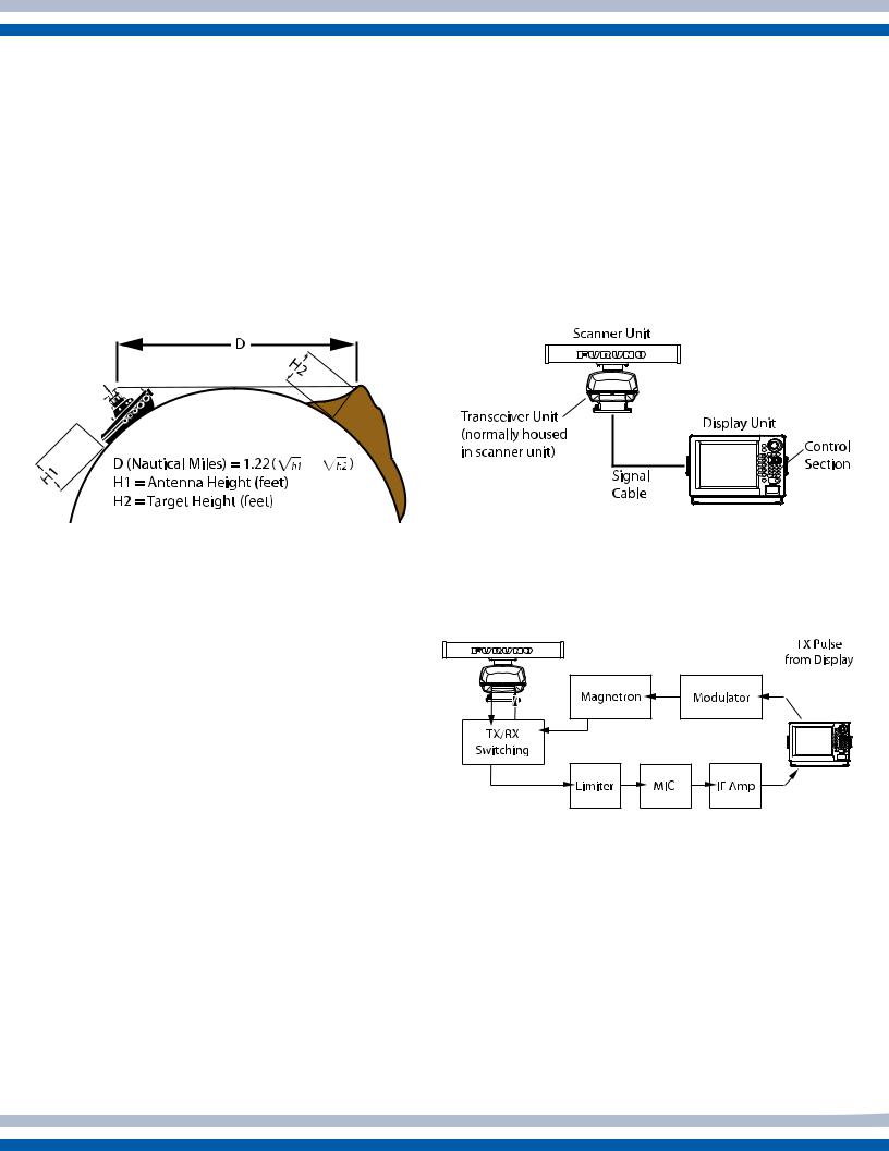
Atmospheric conditions and target shape, material and aspect slightly affect Radar range. However, Radar range is generally calculated as follows:
Radar System Configuration
Basic system
The basic Radar system consists of two units: the scanner unit and the display unit. The transceiver (transmitter/receiver unit, or t/r) is generally housed in the gearbox of the scanner unit. In some designs the t/r is separate from the scanner unit and contained in its own housing; such a unit is referred to as ‘t/r down.’ Also, the control unit may be separate from the display unit so as to allow for custom selection of display in what is referred to as a ‘black box’system.
Figure 1 - Determining Radar range
D is the distance from the scanner to the target horizon. Under normal atmospheric conditions, this distance is 6% greater than the optical horizon. This is because radio waves bend or refract slightly by atmospheric change.
The higher the scanner or target is above the surface, the longer the detection range. For example, if the scanner is 9 meters above the sea surface and the height of the target is 16 meters, you should be able to see the target’s echo on the display when the target is 15 miles from the Radar.
Unusual propagation conditions
Air ducts created by atmospheric conditions can affect radio pulse propagation and thus Radar range. When the radio pulse is bent downward, radio pulses can travel great distances thereby increasing the ranges
at which targets can be detected. This is called superrefraction. The opposite condition, in which Radar waves bend upward and decrease the range at which targets can be detected, is called sub-refraction.
Figure 2 - Basic Radar system
Scanner unit components
Most scanner units employ the circuits and devices shown in Figure 3:
Figure 3 - Circuits and devices of a scanner unit
Magnetron
The magnetron generates the radio pulses.
Magnetrons, as well as the Radar itself, are classified by their transmitting frequency band. There are two main frequency bands in commercial Radar: X-Band (9,000 MHz band; wavelength 3cm) and S-Band (3,000 MHz band; wavelength 10 cm). Magnetron output power ranges from 1kW for small Radars to 60kW for large Radars. Table 1 compares the S-Band
and X-Band frequencies.
3
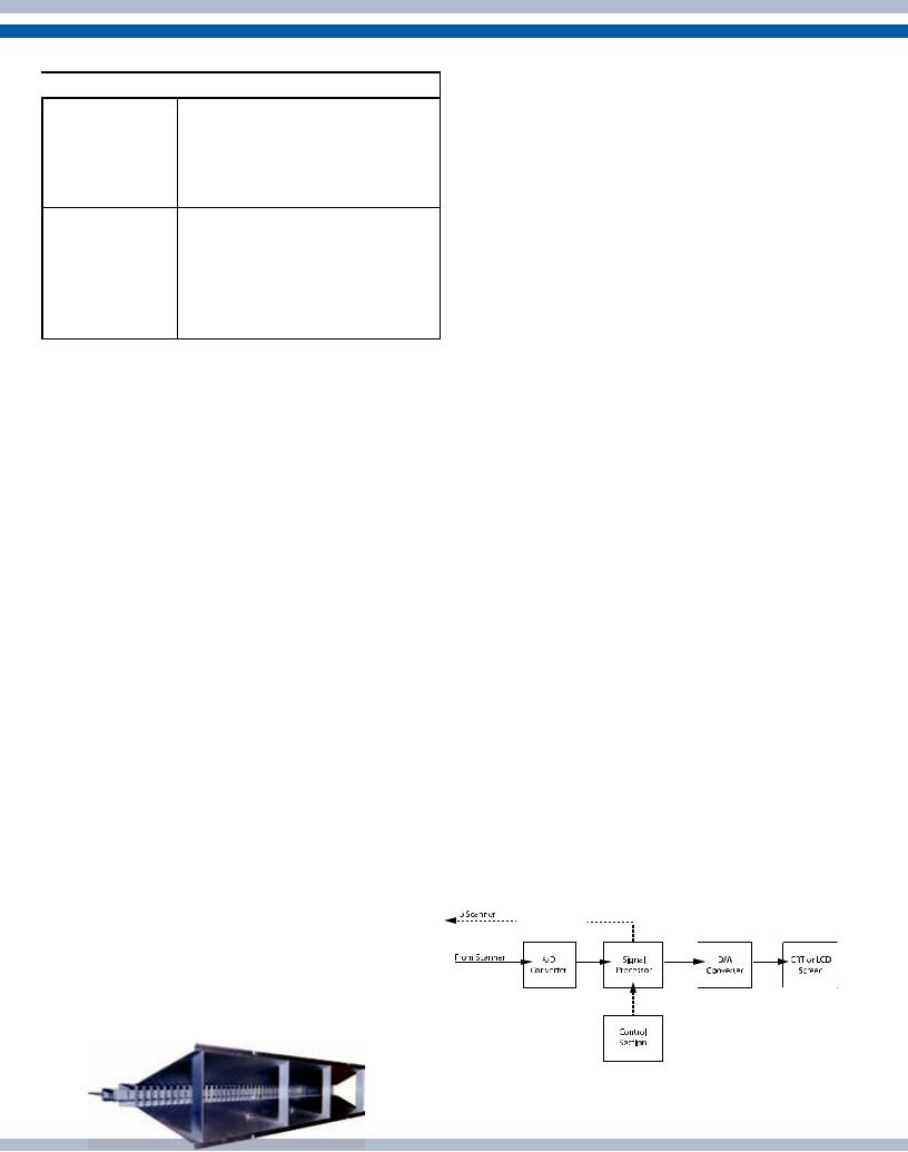
Table 1 - Comparison of X-Band and S-Band
 Frequency Band
X-Band
S-Band
 Characteristics
•Short wavelength for better directivity
•Attenuation in precipitation is greater than on S-Band
•Small, light-weight antennas
•Longer wavelength for long range detection
•Penetrates precipitation for excellent performance in inclement weather
•Large antenna
Modulator
The device responsible for monitoring the magnetron for proper operation is the modulator. It ensures that the magnetron transmits at exactly the same frequency throughout the duration of the pulse, and that the time between pulses is the proper length.
TX/RX Switching
A TX/RX switching device enables the Radar to transmit the radio pulse and receive its reflected echo through one scanner. The switching device used by the Radar is called a circulator It consists of a permanent magnet and a ferrite core. When transmitting, it directs radio pulses to the scanner and disconnects
the receiver circuits. When receiving, it funnels weak reflected echoes away from the magnetron to prevent both flow to the magnetron and loss of receive signal.
Scanner
The scanner transmits the radio pulses and receives their reflected echoes. Most scanners rotate at a constant speed of 24 rpm. Many modern Furuno
Radar scanners rotate at variable speeds dependent upon the range in use in order to optimize Radar detection. The type of scanner used by most vessels is the slotted array, an antenna with a series of slits spaced at suitable intervals and angles from which radio pulses are transmitted. The reflected echoes also pass through these slits.
Figure 4 - A typical slotted array scanner
The length of the array affects horizontal beamwidth, and thus the Radar’s ability to determine target bearing. The longer the array, the more accurately the Radar can determine bearing. For example, an array of 50 cm length gives a horizontal beamwidth of 5 degrees, while one of 300 cm length gives a horizontal beamwidth of 0.75 degrees.
Scanner directivity is a measure of the two beamwidths. One is in the horizontal plane, known as horizontal beamwidth, and the other is in the vertical plane, known as vertical beamwidth. The narrower the horizontal beamwidth the sharper the beam. The vertical beamwidth should be wide; it is typically 20 to 25 degrees. The main reason for a wide vertical beamwidth is to ensure the ability to display a target while own ship is pitching and rolling.
Limiter
The limiter protects the receiver circuits from damage in the event own ship’s Radar receives radio pulses from another ship’s Radar. When this occurs, the limiter attenuates them to protect the next stage MIC (Microwave Integrated Circuit).
MIC
MIC is an acronym meaning Microwave Integrated Circuit. The MIC consists of a local oscillator and mixer circuits. Incorporating those devices on an IC improves quality, reliability, sensitivity and noise figure (nf).
IF Amplifier
The IF amplifier amplifies the Intermediate Frequency signal output by the MIC.
Display unit components
Most display units employ the devices shown in
Figure 5:
4 |
Figure 5 - Devices of a display unit |
|
|
|
|
|
|
A/D Converter
The received IF signal is an analog signal. This signal is converted to a digital signal in order to undergo various processing in the display unit. The A/D (Analog to Digital) converter converts analog signals to digital signals.
Signal Processing
This section is the heart of the Radar and contains computers, memories, and other IC’s. Extensive use of digital techniques permits high speed processing.
Control Unit
The control unit contains various keys and controls for adjustment of the Radar picture. Whenever a control setting is changed the associated reaction appears almost immediately on the display. In some Radar designs, the control unit is separate from the display unit.
Basic Radar Terms
Radar Resolution: Different than display resolution, which is a measure of the pixels in an LCD display, Radar resolution describes the Radar’s ability to distinctly display two Radar targets which are close to each other. Radar has two types of resolution: range, and bearing.
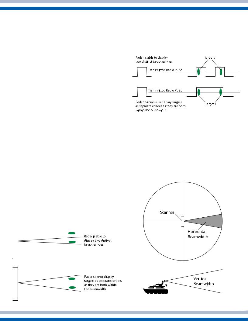
Bearing resolution is a measure of the capability of the Radar to display as separate targets the echoes received from two targets that are at the same range and close together. The principal factor affecting bearing resolution is horizontal beamwidth. The narrower the horizontal beamwidth the better the bearing resolution.
Range resolution is a measure of the capability of the Radar to display as separate pips the echoes received from two targets that are on the same bearing and are close together. The main factor that affects range resolution is pulselength. A short pulselength gives better range resolution than a long pulselength.
Figure 7 - Example of range resolution
Generally, use a short pulselength on short ranges for better range resolution, and a long pulselength on long ranges for longer range detection.
Beamwidth: Beamwidth is the angular width, horizontal or vertical, of the path taken by the Radar pulse. Horizontal beamwidth ranges from 0.75 to
5 degrees, and vertical beamwidth from 20 to 25 degrees.
|
|
|
|
|
|
|
|
|
|
|
|
5 |
|
|
|
|
|
|
|
|
|
|
|
|
|
|
|
|
|
|
|
|
|
|
|
|
|
|
|
|
|
|
|
|
|
|
|
|
|
|
|
|
|
|
|
|
|
|
|
|
|
|
|
|
|
|
|
|
|
|
|
|
|
|
|
|
|
|
|
|
|
|
|
|
|
|
|
|
|
|
|
|
|
|
|
|
|
|
|
|
|
|
|
|
|
|
|
|
|
|
|
|
|
|
|
|
|
|
|
|
|
|
|
|
|
|
|
|
|
|
|
|
|
|
|
|
|
|
|
|
|
|
|
|
|
|
|
|
|
|
|
|
|
|
|
|
|
|
|
|
|
|
|
|
|
|
|
|
|
|
|
|
|
|
|
|
|
|
|
|
|
|
|
|
Figure 6 - Example of |
|
|
|
|
|
Figure 8 - Example of |
|||
|
|
|
|
|
|
|
|
|||||
|
|
|
|
|
|
|
|
|||||
|
|
|
|
|
|
|
|
|||||
|
|
|
|
|
|
|
|
|
||||
|
|
|
|
|
||||||||
|
|
|
bearing resolution |
|
|
|
|
|
scanner beamwidth |
|
||

Pulse Repetition Rate: Pulse repetition rate is the number of radio pulses transmitted in one second. It is automatically determined by pulselength and detecting range. For short ranges, pulselength is short and the pulse repetition rate is high. For long ranges, pulselength is long and the pulse repetition rate is low.
Minimum detectable range: This is the minimum range at which a target is detectable by the Radar. It is determined by scanner height, vertical beamwidth, blind sector within the scanner beam, and pulselength.
Maximum detectable range and output power: Doubling the output power of a typical Radar raises the maximum detectable range by only 19 percent. In the reverse case, halving the output power lowers the maximum detectable range by
16 percent. While you can increase the maximum detectable range by using a high output power Radar, a better (and more economical) way to do it would be to mount the scanner as high as possible above the waterline and/or utilize a longer antenna to increase horizontal beamwidth.
2. RADAR CONTROLS
This section briefly describes the function, objective and usage of Radar controls. Note that some controls described here may not be provided on your Radar.
For detailed control description, refer to your
Operator’s Manual.
Precautions:
A rotating scanner is dangerous. Before turning the Radar on, be sure no one is near the scanner unit.
The scanner unit emits high frequency radio pulses, which can be harmful, particularly to your eyes. Never look directly into the scanner unit when the Radar is in operation.
Key response: The Radar normally releases a beep when you correctly enter a command. If no beep is released, try again. Incorrect command generates several beeps. This function can usually be disabled, but caution must be used as this audible feedback is important to verify correct entry of commands.
Control Description:
Power: Powers the entire Radar system. After turning on the power, a timer displays the time remaining for transmission preparation. “ST-BY” appears when the Radar is ready to transmit. The method of turning off the power varies by model; consult your Operator’s Manual for details on powering off your Radar.
Economy: The economy mode turns off power to the display in stand-by to lessen power consumption.
Trackball/Cursor Pad: The trackball or cursor pad shifts the cursor, which sets the guard zone, displays range and bearing to a target, etc. Some models may have individual arrow keys in place of a trackball or cursor pad.
Scanner: This switch starts and stops scanner rotation. Turning the switch off when transmitting sets the Radar in stand-by. A rotating scanner can be dangerous - before turning the switch on, be sure no one is standing near the scanner unit.
ST BY/TX: Press this key to transmit radio pulses. To stop transmitting, press the key again.
Gain: This control adjusts receiver sensitivity. Adjust the gain to increase sensitivity and display echoes. For long range, adjust the control so background noise
is just visible on the display. For short range, some Radar operators set this control relatively high and adjust sensitivity using the A/C SEA control.
A/C Rain (FTC): The Rain control, also called FTC
(Fast Time Constant), suppresses the reflected echoes from rain, hail and snow to clear the display. On the X band Radar, because of its short pulselength, the echoes from legitimate contacts can become lost in the echoes from precipitation, called rain clutter. When rain clutter masks the display, adjust this control to break up the clutter and distinguish echoes. Adjust the control so that the clutter just disappears; too much
A/C Rain action may shrink or erase the echoes from legitimate targets.
6
 Loading...