


 Loading...
3

The paper used in this manual is elemental chlorine free.
9-52 Ashihara-cho,
Nishinomiya, 662-8580, JAPAN
Telephone : +81-(0)798-65-2111
Fax |
: +81-(0)798-65-4200 |
All rights reserved. |
Printed in Japan |
Pub. No. OME-72660-C
(DAMI ) FI-501/502/505/506
FURUNO Authorized Distributor/Dealer
A : OCT. 2007
C : JAN. 26, 2011
*00016698212*
*00016698212*
* 0 0 0 1 6 6 9 8 2 1 2 *

IMPORTANT NOTICES
General
•The operator of this equipment must read and follow the descriptions in this manual. Wrong operation or maintenance can cancel the warranty or cause injury.
•Do not copy any part of this manual without written permission from FURUNO.
•If this manual is lost or worn, contact your dealer about replacement.
•The contents of this manual and equipment specifications can change without notice.
•The example screens (or illustrations) shown in this manual can be different from the screens you see on your display. The screens you see depend on your system configuration and equipment settings.
•Save this manual for future reference.
•Any modification of the equipment (including software) by persons not authorized by FURUNO will cancel the warranty.
•All brand and product names are trademarks, registered trademarks or service marks of their respective holders.
How to discard this product
Discard this product according to local regulations for the disposal of industrial waste. For disposal in the USA, see the homepage of the Electronics Industries Alliance (http://www.eiae.org/) for the correct method of disposal.
How to discard a used battery
Some FURUNO products have a battery(ies). To see if your product has a battery, see the chapter on Maintenance. Follow the instructions below if a battery is used. Tape the + and - terminals of battery before disposal to prevent fire, heat generation caused by short circuit.
In the European Union
The crossed-out trash can symbol indicates that all types of batteries must not be discarded in standard trash, or at a
trash site. Take the used batteries to a battery collection Cd site according to your national legislation and the Batteries
Directive 2006/66/EU.
In the USA
The Mobius loop symbol (three chasing arrows) indicates that Ni-Cd and lead-acid rechargeable batteries must be
recycled. Take the used batteries to a battery collection site Ni-Cd Pb according to local laws.
i
SAFETY INSTRUCTIONS
 SAFETY INSTRUCTIONS
The operator of this equipment must read these safety instructions before attempting to operate the equipment.
|
|
WARNING |
Indicates a potentially hazardous situation which, if not |
|
||
|
|
avoided, could result in death or serious injury. |
|
|||
|
|
|
|
|
||
|
|
CAUTION |
Indicates a potentially hazardous situation which, if not |
|
||
|
|
avoided, may result in minor or moderate injury. |
|
|||
|
|
|
|
|
|
|
|
|
Warning, Caution |
Prohibitive Action |
Mandatory Action |
|
|
|
|
|
|
|||
Safety instructions for the operator |
Safety instructions for the installer |
|
||||
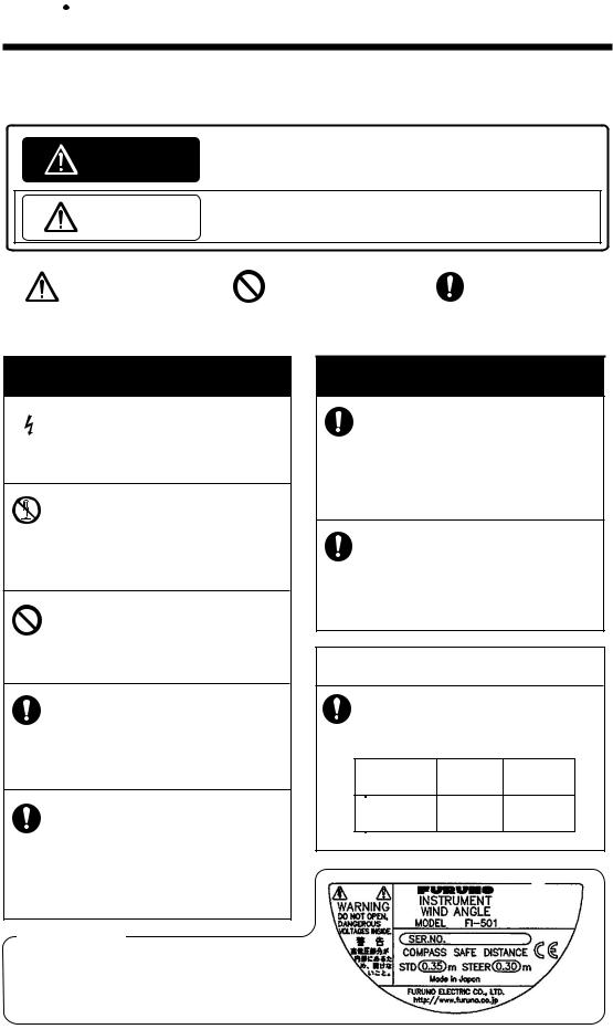
 WARNING
 Do not open the equipment.
Only qualified personnel should work inside the equipment.
Do not disassemble or modify the equipment.
Fire or electrical shock can result if the equipment is modified.
Do not operate the equipment with wet hands.
Electrical shock can result.
Make sure no rain or water splash leaks into the equipment.
Fire or electrical shock can result if water leaks into the equipment.
Immediately turn off the power at the switchboard if water leaks into the equipment.
Continued use of the equipment can cause fire or electrical shock.
 WARNING
Turn off the power at the switchboard before beginning the installation.
Turn off the power to prevent electrical shock.
Make sure the installation site is not subject to water spray.
Fire or electrical shock can result if water leaks into the equipment.
 CAUTION
Observe the following compass safe distances to prevent interference to the instruments:
Standard Steering
compass compass
FI-50 series |
0.35 m 0.30 m |
||||||
Instruments |
|||||||
|
|
|
|
|
|||
|
|
|
|
|
|
|
|
|
|
|
|
|
|
|
|
|
|
|
|
|
|
|
|
|
|
|
|
|
|
|
|
Warning Label
A warning label is attached to the equipment. Do not remove the label. If the label is missing or damaged, contact a FURUNO agent or dealer about replacement.
ii

TABLE OF CONTENTS |
|
|
FOREWORD............................................................................................... |
iv |
|
SYSTEM CONFIGURATION ..................................................................... |
vi |
|
1. FI-501 WIND ANGLE, FI-502 CLOSE HAULED WIND ANGLE............. |
1 |
|
1.1 |
Operating Controls ............................................................................................... |
1 |
1.2 |
Turning the Power On/Off .................................................................................... |
2 |
1.3 |
Adjusting Brilliance and Contrast ......................................................................... |
2 |
1.4 |
Display Layout...................................................................................................... |
3 |
1.5 |
Selecting a Display............................................................................................... |
4 |
1.6 |
Selecting Apparent or True Wind Angle, Wind Speed ......................................... |
5 |
1.7 |
Displaying Velocity Made Good (VMG) Information............................................. |
6 |
1.8 |
Displaying Tack Angle.......................................................................................... |
6 |
1.9 |
Alarms .................................................................................................................. |
7 |
2. FI-505 COURSE PILOT........................................................................... |
9 |
|
2.1 |
Operating Controls ............................................................................................... |
9 |
2.2 |
Turning the Power On/Off .................................................................................. |
10 |
2.3 |
Adjusting Brilliance and Contrast ....................................................................... |
10 |
2.4 |
Selecting a Display............................................................................................. |
11 |
2.5 |
Unlocked and Locked Heading Modes............................................................... |
12 |
2.6 |
Resetting Average Heading Indication ............................................................... |
12 |
3. FI-506 RUDDER..................................................................................... |
13 |
|
3.1 |
Operating Controls ............................................................................................. |
13 |
3.2 |
Turning the Power On/Off .................................................................................. |
14 |
3.3 |
Adjusting Display Brilliance ................................................................................ |
14 |
3.4 |
Calibrating Rudder Angle ................................................................................... |
14 |
4. MAINTENANCE,TROUBLESHOOTING ............................................... |
15 |
|
4.1 |
Preventive Maintenance..................................................................................... |
15 |
4.2 |
Troubleshooting.................................................................................................. |
16 |
5. INSTALLATION..................................................................................... |
17 |
|
5.1 |
Equipment Lists.................................................................................................. |
17 |
5.2 |
Mounting............................................................................................................. |
19 |
5.3 |
Wiring ................................................................................................................. |
23 |
5.4 |
Setting Up........................................................................................................... |
29 |
SPECIFICATIONS ................................................................................. |
SP-1 |
|
PACKING LIST........................................................................................ |
A-1 |
|
OUTLINE DRAWINGS............................................................................. |
D-1 |
|
INTERCONNECTION DIAGRAM ............................................................ |
S-1 |
|
iii

FOREWORD
A Word to the Owner of the FI-501, FI-502, FI-505, FI-506
Congratulations on your choice of the FURUNO FI-501 Wind Angle, FI502 Close Hauled Wind Angle, FI-505 Course Pilot and the FI-506 Rudder, members of the FI-50 series of marine instruments. We are confident you will see why the FURUNO name has become synonymous with quality and reliability.
For over 60 years FURUNO Electric Company has enjoyed an enviable reputation for quality marine electronics equipment. This dedication to excellence is furthered by our extensive global network of agents and dealers.
This equipment is designed and constructed to meet the rigorous demands of the marine environment. However, no machine can perform its intended function unless operated and maintained properly. Please carefully read and follow the recommended procedures for operation and maintenance.
Thank you for considering and purchasing FURUNO equipment.
Features
The FI-50 series provide various analog and digital navigation and environmental data, with digital data displayed on a high quality, backlit LCD. The sturdy weather-proof case is built to stand up to even the harshest of environments.
FI-501, FI-502
The FI-501 Wind Angle and FI-502 Close Hauled Wind Angle provide precise analog wind angle together with digital speed indication. Wind angle is available in True or Apparent.
The main features of the FI-501 and FI-502 are
•True and apparent wind angle and speed
•Maximum wind speed
•Velocity made good
•Tack angle
•Alarms for wind speed and wind angle
•Boat speed
•Boat speed, heading
iv
FOREWORD
FI-505
The FI-505 Course Pilot displays heading and course information, and its main features are
•Heading and average heading
•Locked heading
•Course made good
•Adjustments for
•Heading response
•Pointer response
•Course made good response
•Pointer alignment
FI-506
The FI-506 Rudder displays rudder angle, and its main features are
•Analog rudder indication
•Alignment with keypads
v
SYSTEM CONFIGURATION
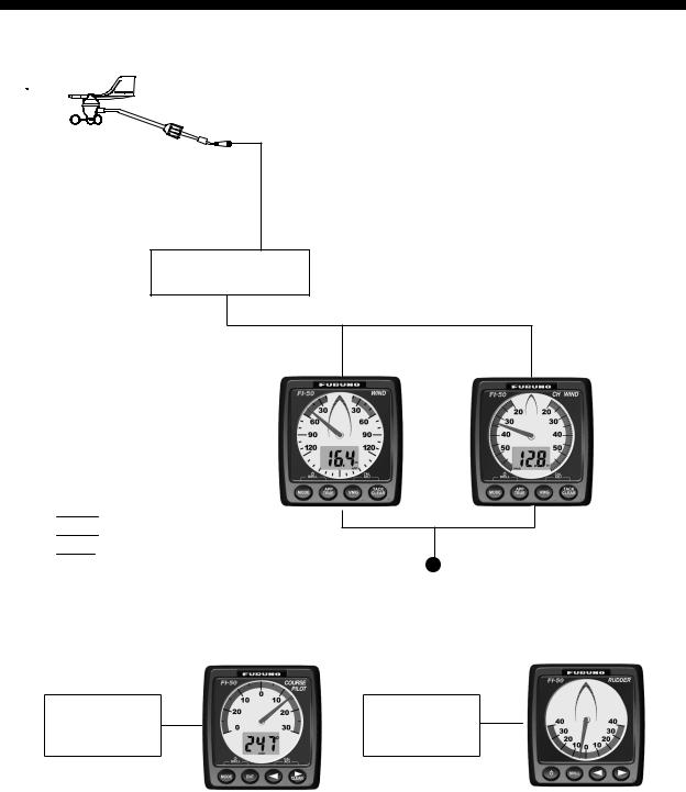
Standalone configuration
FI-5001
WIND
TRANSDUCER
TERMINAL BOX (where necessary)
FI-501
OR
: Standard Supply |
|
: Optional Supply |
|
: Local Supply |
12 VDC |
|
FI-501/FI-502
HEADING |
|
|
AUTOPILOT |
SENSOR |
30 |
|
|
|
|
|
 12 VDC
FI-505 |
FI-506 |
FI-502
 12 VDC
NOTICE: Turn on the terminal resistor in the instrument when connecting a CAN bus device or an NMEA 2000 sensor. For the procedure, see installation chapter.
vi
SYSTEM CONFIGURATION
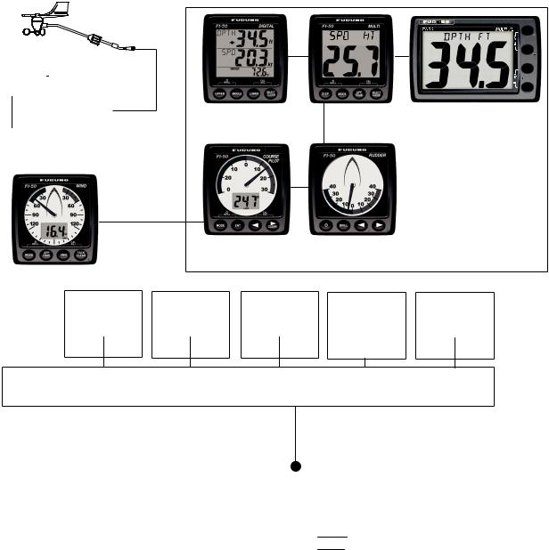
CAN bus network
FI-5001
WIND
TRANSDUCER
SELECT CLEAR 
APP
TRUE
MODE
DISP
TERMINAL BOX |
|
|
|
FI-503 |
FI-504 |
FI-507 |
|||||||
(where necessary) |
|
|
|
||||||||||
|
|
DIGITAL |
MULTI |
MULTI XL |
|||||||||
|
|
|
|
|
|
||||||||
|
|
|
|
|
|||||||||
|
|
FI-501 Wind Angle/ |
|
|
|
|
|
|
|
||||
|
|
FI-502 Close Hauled |
|
|
|
|
|
|
|
||||
|
|
|
Wind Angle |
|
|
|
|
|
|
|
|||
|
|
|
|
|
|
|
|
|
|
|
|
|
|
|
|
|
|
|
|
|
30 |
|
|
|
|||
|
|
|
|
|
|
|
FI-505 |
FI-506 |
|
|
|||
|
|
|
|
|
|
COURSE PILOT |
RUDDER |
|
|
||||
|
|
|
|
|
|
|
|
|
|
|
|
|
|
|
|
|
CAN bus |
|
CAN bus |
|
|
|
CAN bus |
CAN bus |
|
||
|
|
|
|
|
|
|
CAN bus |
|
|||||
|
|
|
Device |
|
Device |
|
|
|
Device |
Device |
Device |
|
|
|
|
|
or |
|
or |
|
|
|
or |
or |
or |
|
|
|
|
|
NMEA 2000 |
|
NMEA 2000 |
|
|
|
NMEA 2000 |
NMEA 2000 |
NMEA 2000 |
|
|
|
|
|
SENSOR* |
|
SENSOR* |
|
|
|
SENSOR* |
SENSOR* |
SENSOR* |
|
|
|
|
|
|
|
|
|
|
|
|
|
|
|
|
|
|
|
|
|
|
|
|
|
|
|
|
|
|
|
|
|
|
|
|
|
|
|
|
|
|
|
|
JUNCTION BOX
FI-5002
*NMEA 2000 SENSORS
-Boat speed
-Depth
- Heading |
12 VDC |
|||
- Navigation |
||||
(not necessary if powered |
||||
- Environment |
||||
by CAN bus network) |
||||
- Autopilot |
||||
|
|
|
||
- Engine |
|
|
: Standard Supply |
|
|
|
|
||
|
|
|
||
|
|
|
: Optional Supply |
|
|
|
|
: Local Supply |
|
NOTICE: Turn on the terminal resistor in the terminator of the CAN bus network.
vii
SYSTEM CONFIGURATION
This page is intentionally left blank.
viii
1.FI-501 WIND ANGLE
FI-502 CLOSE HAULED WIND ANGLE
The FI-501 Wind Angle and FI-502 Close Hauled Wind Angle instruments provide precise analog wind angle together with digital speed indication, in true or apparent direction. Wind speed is displayed in knots, meters/second or as a Beaufort scale number.
In addition to wind direction and speed indications these instruments provide:
•Velocity made good (VMG).
•Alarms for minimum and maximum true wind speeds, and high and low apparent wind angles.
1.1Operating Controls
FI-501 |
FI-502 |
TACK/CLEAR key
- Show tack heading. - Clear data.
- Reset max. true wind. - Increment value.
VMG key
- Show velocity made good. - Decrement value.
APP/TRUE key
Alternate true and apparent wind.
MODE key
-Turn on power.
-Select display.
1

1. FI-501 WIND ANGLE, FI-502 CLOSE HAULED WIND ANGLE
1.2Turning the Power On/Off
To power the instrument, press the MODE key. All LCD segments go on and off and then the last-used display appears.
To power off the instrument, press the MODE and APP/TRUE keys together. The timer appears and counts down from three seconds to one second, and then the power goes off.
Press MODE |
3 |
2 |
1 |
POWER |
and APP/TRUE |
OFF |
keys together
Power OFF sequence
1.3Adjusting Brilliance and Contrast
1.Press the MODE and APP/TRUE keys together. The display for adjustment of brilliance appears, with current brilliance setting flashing.
b=brilliance b 2
Brilliance setting (flashing)
2.Within seven seconds of completing step 1, press the VMG key to lower the brilliance, or the TACK/CLEAR key to raise it.
3.Press the MODE and APP/TRUE keys together. The display for adjustment of contrast appears, with current contrast setting flashing.
C=Contrast C 3
Contrast setting (flashing)
4.Within seven seconds of completing step 3, press the VMG key to lower the contrast, or the TACK/CLEAR key to raise it.
5.Press the MODE and APP/TRUE keys together to save the settings and restore normal operation.
The brilliance and contrast will be the same on all units which are synchronized. (For how to synchronize units, see page 32.)
2

1.FI-501 WIND ANGLE, FI-502 CLOSE HAULED WIND ANGLE
1.4Display Layout
The FI-501 Wind Angle and FI-502 Close Hauled Wind Angle instruments provide analog dial and digital wind information. The display shows that information in true or apparent, depending on mode selected.
The pointer shows the true or apparent wind direction. The apparent wind scale range for the FI-501 is 360{ (0{-179{ starboard, 180{-359{ port) and the FI-502 gives an indication of -60{ to +60{, about the port and starboard of your boat.
Wind angle 

 red: port
 green: starboard

Wind speed (See next page for
other displays.)
FI-501
Wind direction (APParent)
Wind unit (m/s)
Wind angle 

 red: port

 green: starboard
Wind speed
(See next |
Wind unit |
|
(kt) |
||
page for |
||
|
||
other displays.) |
|
FI-502
Wind direction (TRUE)
Displays
3
1. FI-501 WIND ANGLE, FI-502 CLOSE HAULED WIND ANGLE
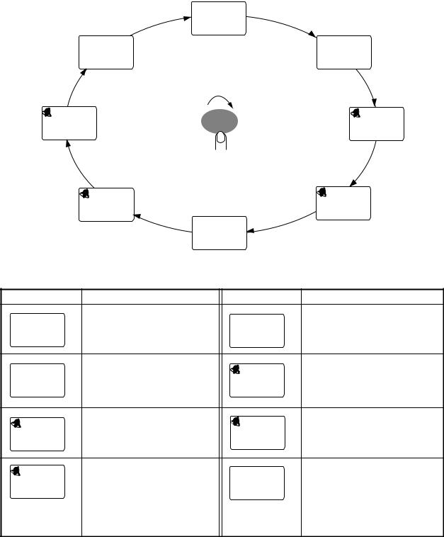
1.5Selecting a Display
Press the MODE key to select a display. Each press of the key changes the display in the sequence shown below.
|
|
|
Wind speed |
|
||
|
|
|
12.5 kt |
|
||
|
|
|
|
APP |
|
|
Beaufort wind |
F12 |
|
|
MAX |
||
speed |
|
|
|
13.5 kt |
||
|
|
|
|
|
TRUE |
|
|
|
|
|
|
Maximum true |
|
|
|
|
|
|
wind speed |
|
200° |
|
|
MAX |
|||
MODE |
20.0 kt |
|||||
|
|
LOHI |
|
|
|
|
Low apparent |
APP |
|
|
TRUE |
||
|
|
|
Maximum true |
|||
wind angle |
|
|
|
|
wind speed |
|
alarm |
|
|
|
|
alarm |
|
|
|
50°HII |
|
|
5.0 kt |
|
|
|
|
|
|
LO |
|
|
|
APP |
|
|
TRUE |
|
|
|
High apparent |
|
HI |
Low true wind |
|
|
|
wind angle alarm |
|
speed alarm |
||
|
|
300° |
||||
|
|
|
|
APP |
|
|
|
|
|
Wind angle |
|
||
Display |
Function |
|
Display |
Function |
||
|
|
Wind speed. Kt or m/s; true |
|
Wind angle. Kt or m/s; true |
||
12.5 |
|
or apparent wind. |
|
HI |
or apparent wind. |
|
|
|
|
|
|||
|
kt |
|
|
300° |
|
|
APP |
|
|
APP |
|
||
MAX |
|
Maximum wind speed. Kt or |
|
Set maximum true wind |
||
|
m/s, true or apparent wind. |
50°HI |
angle alarm.* |
|||
13.5 kt |
||||||
Resettable with the TACK/ |
|
|||||
|
|
|
|
I |
|
|
TRUE |
|
CLEAR key. |
|
TRUE |
|
|
|
|
|
|
|
||
MAX |
|
Set maximum true wind |
|
Set low true wind angle |
||
|
speed alarm.* |
|
200° |
alarm.* |
||
20.0 |
|
|
||||
kt |
|
|
|
|||
|
|
|
TRUE |
|
||
|
|
|
|
LOHI |
|
|
TRUE |
|
|
|
|
|
|
|
|
Set low true wind speed |
|
Beaufort wind speed. Beau- |
||
|
LO |
alarm.* |
|
F12 |
fort speeds up to 12 are |
|
5.0 kt |
|
|
shown. See the table at the |
|||
TRUE |
|
|
|
|
||
|
|
|
|
|
top of the next page for |
|
|
|
|
|
|
Beaufort no. and wind |
|
|
|
|
|
|
speed. |
|
* Audio and visual alarms released when wind speed (or wind angle) is higher (or lower) than threshold value.
4
1. FI-501 WIND ANGLE, FI-502 CLOSE HAULED WIND ANGLE
Beaufort no. and wind speed
Beaufort |
|
Wind speed |
Beaufort |
|
Wind speed |
||||
|
|
|
|
|
|
|
|||
no. |
|
|
|
|
|
no. |
|
|
|
|
kt |
|
m/s |
kt |
|
m/s |
|||
|
|
|
|
|
|||||
|
|
|
|
|
|
|
|
|
|
0 |
|
0 |
|
0-0.2 |
|
7 |
28-33 |
|
14.4-17.4 |
|
|
|
|
|
|
|
|
|
|
1 |
|
1-3 |
|
0.5-2.0 |
|
8 |
34-40 |
|
17.5-21.0 |
|
|
|
|
|
|
|
|
|
|
2 |
|
4-6 |
|
2.1-3.5 |
|
9 |
41-47 |
|
21.1-24.6 |
|
|
|
|
|
|
|
|
|
|
3 |
|
7-10 |
|
3.6-5.6 |
|
10 |
48-55 |
|
24.7-28.8 |
|
|
|
|
|
|
|
|
|
|
4 |
|
11-16 |
|
5.7-8.6 |
|
11 |
56-63 |
|
28.9-32.6 |
|
|
|
|
|
|
|
|
|
|
5 |
|
17-21 |
|
8.7-11.2 |
|
12 |
64 |
|
32.7-32.9 |
|
|
|
|
|
|
|
|
|
|
6 |
|
22-27 |
|
11.3-14.3 |
|
|
|
|
|
|
|
|
|
|
|
|
|
|
|
1.6Selecting Apparent or True Wind Angle, Wind Speed
You can show wind angle and wind speed in apparent or true wind. The apparent wind is the actual flow of air acting upon a sail, or the wind as it appears to the sailor. True wind is the wind seen by a stationary observer in velocity and direction.
With a wind angle or wind speed indication displayed, press the APP/ TRUE key to change the wind angle or wind speed to apparent and true alternately. A beep sounds after the change is completed. (Wind angle and wind speed displays are mutually changed.) True wind requires boat speed input. If there is no speed input three dashes appear.
5.0 HIkt |
135 HI |
APP |
APP |
APP |
APP |
TRUE |
TRUE |
9.6 |
kt |
157 |
HI |
|
HI |
|
|
|
TRUE |
TRUE |
|
Apparent and true |
Apparent and true |
||
wind speeds |
wind angles |
|
|
5
1. FI-501 WIND ANGLE, FI-502 CLOSE HAULED WIND ANGLE
1.7Displaying Velocity Made Good (VMG) Information
VMG is the actual vessel speed after adjusting for such factors as current and wind.
Use the VMG key to display and erase VMG information and current display alternately. (The VMG information cannot be shown when an alarm display is currently shown.). The VMG display requires boat speed information. If no boat speed is available three dashes is shown.
WIND
VMG |
SPEED |
|
|
|
VMG |
|
3.2 kt |
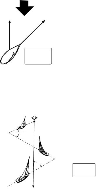
1.8Displaying Tack Angle
Use the TACK/CLEAR key to display tack angle on the digital display. This function requires speed and heading information. If they are not available, the digital display shows three dashes.
Wind
Port
Tack
90°
Starboard
Tack
Port
Tack
° 45
Coming
About
TACK
45°
MAG
Tack angle display (example)
6

1. FI-501 WIND ANGLE, FI-502 CLOSE HAULED WIND ANGLE
1.9Alarms
There are four conditions which trigger audio and visual alarms: Maximum true wind speed, Low true wind speed, High apparent wind angle, and Low apparent wind angle.
1.Press the MODE key to select desired alarm page, referring to the illustration below.
|
|
MAX |
5.0 |
|
|
|
200° |
|
|
20.0 |
LO |
HI |
|||||
|
|
|
50° |
LO |
||||
|
|
|
|
|
|
|
|
|
TRUE |
kt |
TRUE |
kt |
APP |
APP |
|||
Max. true wind |
Low true wind |
High apparent |
Low apparent |
|||||
speed alarm |
speed alarm |
wind angle alarm wind angle alarm |
||||||
|
|
|
|
|
|
|||
Alarm |
|
|
Alarm released when; |
|
Setting range |
|||
Max. true wind |
|
wind speed exceeds this |
|
|
0.1-999 kts |
|
||
speed alarm |
|
threshold. |
|
|
|
|
|
|
|
|
|
|
|
|
|||
Low true wind |
|
wind speed is lower than this |
|
0-998 kts |
|
|||
speed alarm |
|
threshold. |
|
|
|
|
|
|
High apparent |
|
wind angle exceeds this |
|
|
0°-179° (Starboard) |
Angle side (“S” or |
||
wind angle alarm |
|
threshold. |
|
|
|
|
“P”) not indicated |
|
|
|
|
|
|
on FI-501. |
|||
Low apparent |
|
wind angle is lower than this |
|
180°-359° (Port) |
||||
wind angle alarm |
|
threshold. |
|
|
|
|
|
|
2.If the selected alarm page shows “OFF,” press and hold down the TACK/CLEAR key until an alarm setting appears.
3.Press the VMG and TACK/CLEAR keys together to enable adjustment. The alarm setting starts flashing.
4.Press the VMG key to lower the setting; the TACK/CLEAR key to raise it.
Note: A low alarm cannot be set higher than its affiliated high (max.) alarm.
5.Press the VMG and TACK/CLEAR keys together to confirm setting and restore normal operation.
When an alarm is violated:
•The display shows current wind speed and angle.
•The buzzer sounds and the alarm icon flashes.
You can silence the buzzer with the TACK/CLEAR key. The alarm icon continues flashing until the offending alarm is disabled.
While the icon is flashing you can switch between alarm display and current display alternately by pressing the MODE and TACK/CLEAR keys together.
7
1. FI-501 WIND ANGLE, FI-502 CLOSE HAULED WIND ANGLE
This page is intentionally left blank.
8

2.FI-505 COURSE PILOT
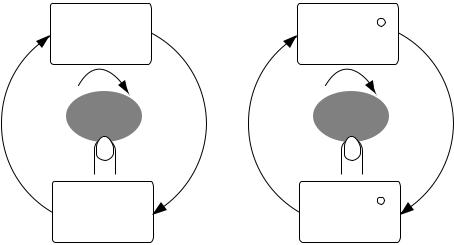
The FI-505 Course Pilot provides compass heading, in digital format. In the locked mode, steering error to ±30° deviation of locked course heading is shown, with the analog pointer.
In the unlocked mode the pointer is set to zero. In the locked mode, the pointer shows course error; that is, the difference between the current heading and the locked course.
2.1Operating Controls
Steering error scale
(for locked mode)
Pointer
30
Heading
(or COG)
 /CLEAR
-Increment value.
-Clear data
-Adjust pointer (heading) rightward, in locked mode.
-Reset average heading.
-Decrement value.
-Adjust pointer (heading) leftward, in locked mode.
ENT
Switch between current heading and locked heading.
MODE
Select display.
9

2. FI-505 COURSE PILOT
2.2Turning the Power On/Off
To power the instrument, press the MODE key. All LCD segments go on and off and then the last-used display appears.
To power off the instrument, press the MODE and ENT keys together. The timer appears and counts down from three seconds to one second, and then the power goes off.
Press MODE |
3 |
2 |
1 |
POWER |
|
and ENT |
|||||
OFF |
|||||
|
|
|
|
keys together
Power OFF sequence
2.3Adjusting Brilliance and Contrast
1.Press the MODE and ENT keys together. The display for adjustment of brilliance appears, with current brilliance setting flashing.
b=brilliance |
b |
2 |
|
Brilliance setting (flashing)
2.Within seven seconds of completing step 1, press the W key to lower the brilliance, or the X/CLEAR key to raise it.
3.Press the MODE and ENT keys together. The display for adjustment of contrast appears, with current contrast setting flashing.
C=Contrast C 3
Contrast setting (flashing)
4.Within seven seconds of completing step 3, press the W key to lower the contrast, or the X/CLEAR key to raise it.
5.Press the MODE and ENT keys together to save the settings and restore normal operation.
The brilliance and contrast will be the same on all units which are synchronized. (For how to synchronize units, see page 32.)
10
Loading...