


 Loading...
C
9 - 5 2 , A s h i h a r a - c h o , N i s h i n o m i y a , J a p a n
T e l e p h o n e : |
0 7 9 8 |
- 6 5 |
- 2111 |
T e l e f a x : |
0 7 9 8 - 6 5 - 4 2 0 0 |
||
A l l r i g h t s r e s e r v e d . Printed in Japan
|
P U B . N o . O M E -5 5 7 2 2 |
( Y O S H ) |
F S - 1 5 6 2 - 1 5 / 2 5 |
 Y o u r L o c a l A g e n t / D e a l e r
F I R S T E D I T I O N : |
O C T . 1 9 9 3 |
|
N 1 |
: |
A U G . 1 9 , 2 0 0 2 |

 SAFETY INSTRUCTIONS
"DANGER", "WARNING" and "CAUTION" notices appear throughout this manual. It is the responsibility of the operator of the equipment to read, understand and follow these notices. If you have any questions regarding these safety instructions, please contact a
FURUNO agent or dealer.
The level of risk appearing in the notices is defined as follows:
This notice indicates a potentially
hazardous situation which, if not DANGER avoided, will result in death or
serious injury.
This notice indicates a potentially
hazardous situation which, if not WARNING avoided, could result in death or
serious injury.
This notice indicates a potentially
hazardous situation which, if not CAUTION avoided, could result in minor or
moderate injury, or property damage.
i
 DANGER
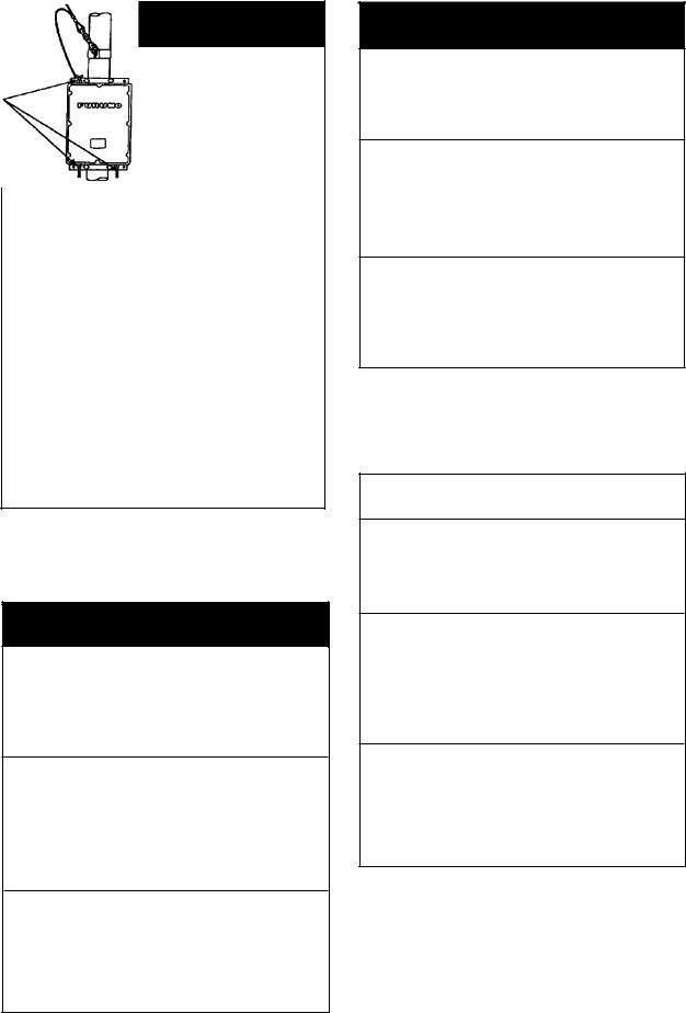
Do not work inside the equipment unless totally familiar with electrical circuits.
Hazardous voltage which will cause death or serious injury exists at the following locations:
•Transceiver unit
•Antenna and antenna coupler (both at TX)
HAZARDOUS VOLTAGE is present at these points.
ANTENNA COUPLER
 WARNING
Do not disassemble or modify the equipment.
Fire, electrical shock or serious injury can result.
Turn off the power immediately if water leaks into the equipment or the equipment is emitting smoke or fire.
Continued use of the equipment can cause fire or electrical shock.
Do not place liquid-filled containers on the top of the equipment.
Fire or electrical shock can result if a liquid spills into the equipment.
 WARNING
Do not operate the equipment with wet hands.
Electrical shock can result.
Keep heater away from equipment.
Heat can alter equipment shape and melt the power cord, which can cause fire or electrical shock.
Any repair must be done by a licensed radio technician.
Improper repair work can cause fire or electrical shock.
 CAUTION
Use the proper fuse.
Use of a wrong fuse can result in fire or permanent equipment damage.
Do not use the equipment for other than its intended purpose.
Personal injury can result if the equipment is used as a chair or stepping stool, for example.
Do not place objects on the top of the equipment.
The equipment can overheat or personal injury can result if the object falls.
ii
LIST OF CONTENTS
INTRODUCTION .................................................................................................. |
iv |
|
Specifications of MF/HF Radiotelephone model FS-1562 ...................................... |
v |
|
Chapter 1 |
OPERATION ................................................................................ |
1.1 |
1.1 |
SYSTEM SET-UP ........................................................................ |
1.1 |
1.2 |
Front View of Transceiver Unit .................................................... |
1.2 |
1.3 |
Power Supply Unit ....................................................................... |
1.4 |
1.4 |
Starting operation ......................................................................... |
1.5 |
1.5 |
Selecting Frequency ..................................................................... |
1.5 |
1.6 |
Transmitting ................................................................................ |
1.10 |
1.7 |
Distress Call on 2182 kHz .......................................................... |
1.11 |
1.8 |
In the Event of Antenna Coupler Failure .................................... |
1.13 |
1.9 |
DSC Distress Calling .................................................................. |
1.13 |
1.10 |
Receiving .................................................................................... |
1.14 |
1.11 |
Frequency Scan .......................................................................... |
1.15 |
1.12 |
Frequency Sweep........................................................................ |
1.16 |
Chapter 2 |
OPERATION of OPTIONAL DEVICES ..................................... |
2.1 |
2.1 |
Telex Communication................................................................... |
2.1 |
2.2 |
Intercom ........................................................................................ |
2.2 |
2.3 |
Remote Station ............................................................................. |
2.2 |
Chapter 3 |
CHANGING SYSTEM SETTING .............................................. |
3.1 |
3.1 |
SYSTEM SETUP ......................................................................... |
3.1 |
3.2 |
CUSTOMIZING BY OPERATOR ............................................... |
3.1 |
Chapter 4 |
MAINTENANCE ......................................................................... |
4.1 |
4.1 |
Weekly Checks ............................................................................. |
4.1 |
4.2 |
Diagnostic Test ............................................................................. |
4.1 |
4.3 |
LCD/Keyboard Test & ROM Version No. Confirmation ............. |
4.3 |
4.4 |
Antenna Coupler Test ................................................................... |
4.4 |
4.5 |
Maintenance ................................................................................. |
4.5 |
Chapter 5 |
TROUBLESHOOTING ............................................................... |
5.1 |
5.1 |
Troubleshooting List ..................................................................... |
5.1 |
5.2 |
Error Indication ............................................................................ |
5.3 |
5.3 |
Replacing Fuses ............................................................................ |
5.3 |
APPENDIX |
........................................................................................................ |
AP.1 |
Declaration of conformity to type
iii
INTRODUCTION
FURUNO Electric Company thanks you for selecting the FS-1562 MF/HF SSB Radiotelephone. We are confident you will discover why FURUNO has become synonymous with quality and reliability. To get maximum performance from your unit, please carefully read and follow the recommended procedures for operation and maintenance.
The FS-1562 is an all-purpose radiotelephone system especially designed for marine mobile communication in the frequency range 1.6 to 27.5 MHz. All ITU channels are preprogrammed. In addition, TX/RX frequencies can be preprogrammed into a E2 PROM having a capacity of 200 frequency pairs.
There are two types of the FS-1562: FS-1562-15 (150 Wpep) and FS-1562-25 (250 Wpep), where pep is peak envelope power, the unit for addressing an output power in a Single Sideband (SSB) transmitter.
•Installation information is contained in the installation manual.
•System initialization after installation is described in the service manual.
Features
•GMDSS operation: DSC and NBDP connections
•2182 key provides for immediate selection of 2182 kHz (at FULL power automatically)
•Scan/Sweep receiving function
•PROM stores all ITU SSB and TELEX frequencies
•Dummy load (in the Antenna Coupler) permits checking of transmitter
•Effective noise blanker cancels pulse noise
•Advanced “voice” detecting type squelch circuit filters out noise
•Remote station (RB-500) optionally available
•System diagnostics program
•The AC FAIL Board (option) functions to reduce Tx power automatically when AC power fails (only FS-1562-25).
Notes
1.Use a battery having sufficient capacity (more than 120 AH for 150 W set, 200 AH for 250 W set). Otherwise, battery cannot provide sufficient transmission power.
2.Handle the microphone carefully. Heat, humidity and shock will affect performance.
3.Do not adjust the potentiometers inside the unit. Improper adjustment may cause serious damage.
iv
Specifications of MF/HF Radiotelephone model FS-1562
The model FS-1562-15/25 complies with the following rules and regulations:
-IMO A.421(XI), A.610(15), A613(15), A.694(17)
-International Convention on Safety of Life at Sea 1974, as amended 1988 (GMDSS Conference)
-ITU Radio Regulations
-ETS 300 373
-IEC 1097-9 draft, IEC 945 General Requirements
-EC EMC Directive for CE marking requirements
-Other relevant rules
GENERAL
Communication System |
Simplex or semi-duplex |
||
Frequency Range |
1.6 to 27.5 MHz (transmit), 0.1 to 30 MHz (receive) |
||
Frequency Resolution |
Transmit: 100 Hz |
Receive: 10 Hz |
|
Class of Emission |
J3E |
SSB, suppressed carrier, signal channel containing analogue information, telephony; |
|
|
|
when 2182 kHz is first selected, H3E is set. |
|
|
H3E |
SSB, full carrier, signal channel containing analogue information. |
|
|
J2B |
for DSC, NBDP; SSB, suppressed carrier, signal channel containing quantized |
|
|
|
or digital information with the use of a modulating sub-carrier, telegraphy for |
|
|
|
automatic reception |
|
|
F3C |
weather facsimile, reception only |
|
Frequency Error |
±10 Hz (Both Transmitter and Receiver) |
||
Number of Channels |
Custom channels: 200 max programmed by Furuno authorized service representatives |
||
|
ITU SSB/TELEX Channels as listed in Appendix |
||
|
2182 kHz (single action) |
||
|
2187.5 kHz (automatically selected on DSC equipment) |
||
Environmental |
IEC 945: -15°C to +55°C Transceiver unit, -25°C to +70°C ACU; 93% at 40°C |
||
Power Supply |
24 VDC +30%, -10%. For AC, a rectifier unit required. |
||
|
Receive: |
2 A |
|
|
Transmit (max.): |
FS-1562-15...20 A |
|
|
|
|
FS-1562-25...40 A |
Radiotelephone Signal Generator |
Two tones of 2200Hz and 1300Hz transmitted alternately. |
||
TRANSMITTER
Output Impedance |
50 ohms |
|
|
Output Power |
J3E/H3E: |
FS-1562-15...150 W pep, |
FS-1562-25...250 W pep |
|
J2B: |
FS-1562-15...150 W pep, |
FS-1562-25...250 W pep |
|
|
(FEC mode: reduced to 60 W) |
|
|
Tune: 10 to 20 W approx. |
|
|
Power Reduction |
60 W |
|
|
Controls |
Output HI/LOW, test |
|
|
ANTENNA COUPLER
Power Capability |
AT-1560-15...150 W pep |
|
AT-1560-25...250 W pep |
Tuning System |
CPU controlled fully automatic tuning system |
v
Frequency Range |
1.6 to 27.5 MHz |
Input Impedance |
50 ohms (viewed from transceiver) |
Antenna Required |
7 to 30 meters wire or whip |
Tuning Power |
10 to 20 W pep |
VSWR |
Less than 1.5 |
Tuning Time |
Within 2 to 15 seconds, Within 0.5 seconds for an ever tuned frequency |
Dummy Load |
10 ohms + 250 pF for check of Two-tone alarm generator at 2191 kHz |
Power Requirement |
15 VDC, 1A (supplied from transceiver) |
Construction |
Waterproof plastic cabinet, stainless steel mount |
RECEIVER
Receiving System |
Double-conversion superheterodyne |
|
|
|
|
IF: 54.455 MHz and 455 kHz. |
|
|
|
Sensitivity |
Input level to produce SINAD 20 dB, or BER 10-2 |
|
||
|
|
J3E |
J2B |
across 10 Ω + 250 pF |
|
1.6 - 4 MHz |
Below +16 dBμV |
Below +6 dBμV |
|
|
4-27.5 MHz |
Below +3 dBμV |
Below -7 dBμV |
across 50 Ω |
Pass Band |
350 - 2700 Hz |
-6 dB |
|
|
Cross Modulation |
Unwanted signal +90 dBμV ±20 kHz from +60 dBμV wanted signal |
|||
Audio Output |
2 W (8 Ω internal loudspeaker), 5 W (4Ω optional external loudspeaker) |
|||
|
0 dBm/600Ω line output (for NBDP, DSC) |
|
||
Other Features |
RF Gain: |
Adjustable |
|
|
|
Squelch: |
ON/OFF, Activated by voice/signal strength |
||
|
Dimmer: |
OFF/Low/Medium/High |
|
|
|
Loudspeaker: |
ON/OFF (Handset always alive) |
|
|
|
AGC: |
ON/OFF |
|
|
|
Noise blanker: |
always ON |
|
|
POWER AMP UNIT (Type PA-2500 for FS-1562-25)
Power capability |
Input Power: 60 Wpep, Output Power: 250 Wpep |
Input/Output Impedance |
50 ohms |
Power Supply |
24 VDC, 30 A |
DIMENSIONS
Transceiver Unit |
108 mm(W) x 258 mm(H) x 300 mm(D), 6.5 kg |
Antenna Coupler Unit |
297 mm(W) x 390 mm(H) x 90 mm(D), 3.1 kg approx. |
COMPASS SAFE DISTANCE
|
|
|
|
|
|
|
Unit |
Standard |
Steering |
NOTE |
|
|
Transceiver |
1.2 m |
0.9 m |
|
|
|
Antenna coupler AT-1560-15 |
1.0 m |
0.7 m |
Furuno recommendation based on the |
|
|
Antenna coupler AT-1560-25 |
1.0 m |
0.7 m |
ISO R 694 Method A tests for the |
|
|
Handset |
0.6 m |
0.4 m |
variant models, added with correction |
|
|
PA-2500 |
0.9 m |
0.7 m |
factors which Furuno considers |
|
|
PR-300 |
0.9 m |
0.7 m |
adequate. |
|
|
|
|
|||
|
PR-850A |
1.0 m |
0.7 m |
|
|
|
|
|
|
|
|
vi

Chapter 1 OPERATION
1.1 SYSTEM SET-UP
The basic 24 VDC FS-1562 consists of a Transceiver Unit, a Power Amp Unit (for 250 W), an Antenna Coupler, and a Handset. Shown below are the system setup for 150 W and 250 W with DSC (Digital Selective Calling) terminal and other ancillaries.
|
|
|
|
|
|
|
|
|
|
|
|
FS-1562-15 SYSTEM DIAGRAM |
||
Antenna Coupler |
|
|
|
|
|
|
|
|
|
|
|
|
DSC Terminal |
|
|
|
|
|
|
|
|
|
|
|
|
|
DSC-60 |
|
|
AT-1560-15 |
|
|
|
|
|
|
|
|
|
|
|
|
NBDP Terminal |
|
|
|
|
|
|
|
|
|
|
|
|
|
|
DP-6 |
|
|
|
|
|
|
|
|
|
|
|
|
|
|
Remote Station |
|
|
|
|
|
|
|
|
|
|
|
|
|
|
RB-500 |
|
Transceiver Unit |
|
|
|
|
|
|
|
|
|
|
Distributor |
|
||
|
|
|
|
|
|
|
|
|
|
DB-120 |
|
|||
Telephone |
|
|
|
|
|
|
|
|
|
|
|
|
|
|
|
|
|
|
|
|
|
Rectifier with |
|
|
|||||
Handset |
|
SSB TRANSCEIVE FS-1562-15 |
|
|
|
|
|
|
||||||
|
|
|
MODE CURS CLARIFY |
|
|
|
||||||||
|
|
|
1 |
2 |
3 |
TX |
changeover facility |
|
|
|||||
|
|
|
|
SQ |
SCAN |
|
|
|
||||||
|
|
|
R |
4 |
5 |
6 |
RX |
|
|
|||||
External |
|
|
AGC NB |
TX TUNE HI LOW |
|
|
|
|
||||||
|
|
7 |
8 |
9 |
RCL |
|
|
PR-300 |
|
|
|
|||
|
|
H3E |
|
INTERCOM |
START |
|
|
|
|
|
||||
|
|
|
2182 |
0 |
ALARM |
ENT |
|
|
|
|
|
|||
MIC |
VOLUME |
RF GAIN |
FREQ/CH |
TEST |
STOP |
|
|
|
|
|
||||
Speaker |
|
OFF |
|
|
S/N: |
|
|
|
|
|
|
|
DSC Terminal |
|
|
|
|
|
|
|
|
|
|
|
PR-300 |
|
|
||
|
|
|
|
|
|
|
|
100V 10A |
|
125V 20A |
|
|
DSC-60 |
|
|
|
|
|
|
|
|
|
220V 5A |
|
|
|
|
||
|
|
|
|
|
|
|
|
ON |
|
ON |
|
|
|
|
|
|
|
|
|
|
|
|
OFF |
|
OFF |
|
|
|
|
|
|
|
|
|
|
|
|
|
AC IN |
DC IN |
DC OUT |
|
|
|
|
|
|
|
|
|
|
|
L |
N |
G + - |
+ - 24V + |
- |
|
|
|
|
|
|
|
|
|
|
|
|
|
|
|
NBDP Terminal |
|
|
|
|
|
|
|
|
|
115/230 VAC |
24 VDC |
DP-6 |
Option |
|||
|
|
24 VDC |
|
|
|
|
||||||||
|
|
|
|
|
|
|
||||||||
|
|
|
|
|
|
|
|
|
|
|
FS-1562-25 SYSTEM DIAGRAM |
|||
Antenna Coupler
AT-1560-25
Power Amp |
DSC Terminal |
PR-2500 |
DSC-60 |
|
NBDP Terminal |
|
DP-6 |
|
Remote Station |
Transceiver Unit |
RB-500 |
|
Telephone |
|
|
|
|
|
|
|
|
Handset |
|
SSB TRANSCEIVE FS-1562-15 |
|
|
|
|
|
|
|
|
|
|
SQ |
SCAN |
|
|
|
|
|
|
|
MODE CURS CLARIFY |
|
|
||
|
|
|
|
1 |
2 |
3 |
TX |
Distributor |
|
|
|
AGC NB |
7 |
8 |
9 |
RCL |
|
|
|
|
R |
4 |
5 |
6 |
RX |
|
External |
|
|
|
TX TUNE HI LOW |
|
|
|
|
MIC |
VOLUME |
RF GAIN |
FREQ/CH |
TEST |
STOP |
DB-120 |
||
|
|
OFF |
H3E |
|
INTERCOM |
START |
||
|
|
|
2182 |
S/N: |
ALARM |
ENT |
||
|
|
|
|
0 |
|
|||
Speaker |
|
|
|
|
|
|
|
|
AC FAIL |
ON |
|
|
POWER |
|
|
ON |
DSC Terminal |
|
OFF |
|
|
|
DSC-60 |
|
AC INPUT 50/60Hz |
DC OUTPUT |
Rectifier with |
|
NBDP Terminal |
changeover facility |
||
PR-850A |
115/230 VAC |
DP-6 |
24 VDC |
24 VDC |
|
Option
-1.1-
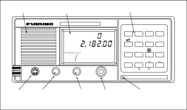
1.2 Front View of Transceiver Unit
(Same for FS-1562-15 and FS-1562-25) |
|
|
|
|
|||||||
Loudspeaker |
Operation Display |
Keyboard |
|
|
|||||||
|
|
SSB TRANSCEIVE FS-1562-15 |
|
|
|
||||||
|
|
|
|
|
|
|
|
MODE |
CURS CLARIFY |
|
|
|
|
|
|
|
|
|
|
1 |
2 |
3 |
TX |
|
|
|
|
|
|
|
|
|
SQ |
SCAN |
|
|
|
SIMP |
|
R |
|
|
4 |
5 |
6 |
RX |
|
|
|
|
|
|
|
|
|
|
|||
|
|
0 |
2 |
4 |
6 |
8 |
10 S |
TX TUNE HI LOW |
|
|
|
|
|
|
|
|
|
|
|
|
|
||
|
|
|
|
|
|
|
AGC NB |
7 |
8 |
9 |
RCL |
|
|
|
|
|
|
|
|
H3E |
INTERCOM |
START |
|
|
|
|
|
|
|
|
|
|
|||
|
MIC |
VOLUME |
|
|
|
RF GAIN |
2182 |
0 |
ALARM |
ENT |
|
|
|
|
|
FREQ/CH |
TEST |
STOP |
|||||
|
|
|
|
|
|
|
|
|
|||
|
|
OFF |
|
|
|
|
|
|
S/N: |
|
|
|
|
|
|
|
|
|
|
|
|
|
|
Microphone |
Volume control |
|
|
RF GAIN |
FREQ/CHANNEL |
Xtal oven light |
|||||
Hndset Jack |
w/Power ON/OFF |
|
|
control |
selector |
(LED) |
|
|
|||
Rotary controls
VOLUME |
Turns the power on and off and adjust the loudspeaker volume. |
|
When FS-1562 is connected to DB-500 and RB-500, FS-1562 can be turned |
|
on by RB-500. |
|
This is possible with the RB-500 having ROM version 1.04 and after. |
RF GAIN |
Adjusts the receiver sensitivity. |
FREQ/CH |
Changes the frequency in conjunction with the [TX] or [RX] key. Also changes |
|
the channel numbers set with the [RCL] key. |
Keys |
|
[1] (MODE) |
Selects a class of emission and controls AGC on and off. Press the [1] key |
|
repeatedly until the wanted class of emission appears. |
[2] (CURSor) |
Shifts cursor (underline marking). Press the [2] key to move the cursor. |
[3] (CLARIFY) |
Adjusts the receiver frequency for fine tuning when the frequency is set in |
|
terms of Channel NO. Not active in direct frequency entry. The adjustable |
|
range is ±150 Hz in 10 Hz steps. |
[TX] |
Selects a TX frequency. |
[4] (speaker) |
Turns the internal or external loudspeaker on or off. The speaker mark appears |
|
on the display when the speaker is off. |
-1.2-
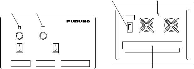
1.3 Power Supply Unit
The transceiver unit FS-1562-15 or FS-1562-25 works direct on 24 VDC or through a Power Supply Unit on AC mains supply (115 or 230 VAC). The power supply unit is type PR-300 supplying 24 VDC power (20 A) to the FS-1562-15 (150 W) Transceiver Unit or type PR-850A, supplying 24 VDC (40 A) for the FS-1562-25 (250 W). Both 115/230 VAC and 24 VDC power can be connected simultaneously. In this case, the system normally operates on the AC mains supply and when AC power is lost, the PSU automatically switches to the DC power source.
This power supply arrangement satisfies the GMDSS requirements. The FS-1562-15/25 can be operated direct from 24 VDC without a rectifier unit.
OVEN power supply: The crystal oven is always powered even when the Power Switch is OFF. It draws 50 mA approx. The Oven LED lights while the oven is powered.
AC and DC power switches
Both AC and DC power switches on the PSU can be always kept “on”. (These switches are provided to turn off the power supply for maintenance.) The transceiver may be turned on or off with the PSU kept on.
BREAKER |
POWER LAMP |
RED LIGHT GREEN LIGHT
POWER
ON
ON
PR-300
OFF
100V |
10A |
125V 20A |
|
220V |
5A |
||
|
ON |
ON |
|
|
OFF |
OFF |
|
|
AC IN |
DC IN |
DC OUT |
- |
L N G |
+ - |
+ - 24V + |
AC INPUT 50/60Hz |
DC OUTPUT |
TERMINAL COVER
FRONT PANEL OF PR-300 |
FRONT PANEL OF PR-850A |
Lamp (red): Lights when AC power source is in use.
Lamp (green) Lights when DC power source is in use.
NOTE: Both lamps light when changing to DC power supply (PR-300). These lamps also light when the internal temperature excessively rises. The PR-300 or PR-850A is not required on 24 VDC vessels.
Fuses
The PR-300 has 2 fuses, each for AC and DC power.
100-120 VAC: |
10 A |
200-240 VAC: |
5 A |
DC fuse: |
20 A |
The PR-850A has a breaker and a power lamp on the front panel. The fuse is provided in the power cable.
-1.4-
1.4 Starting operation
The power switch is combined with the Volume Control. Turn the Volume Control clockwise until you hear a click. Further clockwise rotation of the control raises the loudspeaker volume. To turn off the power, turn the control fully counterclockwise until you hear the click.
Adjusting the backlighting:
The dimmer [9] key adjusts the backlighting for the operation display and the keyboard. Each time the key is pressed, the backlighting changes in the sequence of high, medium, low and off.
Turning the loudspeaker on or off:
When you are using a handset and therefore do not require the internal or external loudspeaker, you can turn it off by pressing the loudspeaker [4] key. The “loudspeaker off mark” appears .
Turning the squelch on or off:
The squelch mutes the audio output in the absence of an incoming signal. Each time the [5] key is pressed, the squelch is turned on or off. When radio noise is too jarring during stand-by condition, it may be muted by activating the squelch. “SQ” appears when the squelch function is active.
NOTE: The squelch is disabled on the class of emission TLX or FAX; “SQ” blinks.
Selecting class of emission/turning AGC on or off:
The MODE [1] key selects the class of emission and turns the AGC on or off. Each time the key is pressed, the class of emission changes and AGC is turned on or off in the following sequence. “AGC” appears on the display when AGC is active (ON).
J3E AGC ON → J3E AGC OFF → H3E AGC ON → H3E AGC OFF
− |
|
↓ |
FAX* AGC OFF ← FAX * AGC ON ← TLX AGC OFF ← TLX AGC ON |
||
Indication |
Symbol |
Class of Emission |
J3E |
J3E |
Single Sideband radiotelephony |
H3E |
H3E |
Equivalent to AM radiotelephony. |
TLX |
J2B |
Radio Telex |
FAX |
F3C |
Reception of weather facsimile broadcast |
|
|
(*available with system setting by Furuno authorized service agent) |
1.5Selecting Frequency
Frequency can be selected by;
-Direct key entry (Free selection within marine bands for Netherlands or for ship stations where a qualified Radio Operator is available)
-Channel number entry
-FREQ/CH selector
A receiving frequency can be selected by one of the above methods, but there is a restriction in selecting a transmitting frequency. This depends on how the equipment is programmed according to the national radio regulation.
-1.5-
The frequencies are indicated by:
Voice frequencies: |
Designated by the CARRIER frequency. Assigned frequencies are 1.4 |
||||
|
|
kHz higher than the carrier frequencies. |
|
|
|
Telex, DSC: |
Designated by the CENTER frequencies |
|
|
||
|
|
|
|
|
|
|
|
|
|
|
|
|
TX Freq |
Standard type |
Netherlands type |
Special type |
|
|
selection |
|
|||
|
|
|
|
|
|
|
Free selection |
NO |
YES (Marine band only) |
YES |
|
|
|
|
indicated by frequency |
indicated by frequency |
|
|
|
|
|
|
|
|
ITU Channels |
All channels in the APPENDIX |
Indicated by CH or |
|
|
|
|
Indicated by frequency |
frequencies as required |
|
|
|
|
|
|
|
|
|
Custom Channels |
YES, indicated by frequency |
Indicated by CH or |
|
|
|
|
Preset by Furuno authorized service agent |
frequencies as required |
|
|
|
|
|
|
|
|
|
|
- Asia |
- Netherlands in Sea |
if required on ship with |
|
|
|
area A2-4 |
|
||
|
User countries |
- CEPT countries |
competent radio personnel, |
|
|
|
- USA ships calling |
|
|||
|
|
- USA |
subject to Authorities |
|
|
|
|
foreign coastal stations |
|
||
|
|
|
|
|
|
|
|
|
|
|
|
|
|
|
|
|
|
-1.6-

Direct frequency entry
Free selection is possible in Dutch Version (in marine bands only).
RX: To set for a receive frequency of 1636.4 kHz, for example;
Press [RX], [1], [6], [3], [6], [4], [ENT] in this order. The decimal point is not required to enter. TX: To set for a transmit frequency of 2061.4 kHz, for example;
Press [TX], [2], [0], [6], [1], [4], [ENT].
DUP
R
0 2 4 6 8 10 S
SQ
AGC NB
J3E
•The [2] Cursor key shifts the cursor among last 4 places.
•To modify a value at a particular digit (receive frequency only), you can use the rotary control. The FREQ/CH control changes the value above the cursor.
Paired RX/TX: To set for 2161 kHz simplex channel, for instance, press as below;
[RX], [TX], [2], [1], [6], [1], [0], [ENT].
Do not miss the last zero in the above example. The last numeral represents the 1/10 decimal place. Simply hitting [RX], [TX], [2], [1], [6], [1], [ENT] will set 216.1kHz.
-1.7-

Custom channels
Up to 200 custom channels can be programmed in addition to 412 ITU channels. You can recall them through the keyboard by channel numbers. Once a channel is selected with the keyboard, the channel can be changed with the FREQ/CH rotary selector.
NOTE: Custom channel programming should be done by a FURUNO service agent.
To call the channel 120, for example:
TX only
Press [TX], [RCL], [1], [2], [0], [ENT]
RX only
Press [RX], [RCL], [1], [2], [0], [ENT]
TX and RX paired
Press [RCL], [1], [2], [0], [ENT]
NOTE: The standard sets provide readout of frequencies in kHz. Pressing the [ENT] key or operating the FREQ/CH selector shows up the CH NO. temporarily.
ITU telephony channels (SSB)
To recall ITU SSB channel 412, for example, select J3E with the [MODE] key.
Press [RCL], [4], [1], [2], [ENT], and a combination of TX frequency of 4098 kHz and RX frequency of 4390 kHz is selected. To select only RX or TX frequency, hit [RX] or [TX] to start with.
RX freq |
TX freq |
BAND ITU CHANNEL NO. |
DUP
R
0 |
2 |
4 |
6 |
8 |
10 |
S |
AGC NB
J3E
Frequency indication type. Frequencies are normally displayed. CH NO. is also displayed temporarily by operating the FREQ/CH selector or by pressing the [ENT] key.
DUP
R
0 2 4 6 8 10 S
AGC NB
J3E
Channel NO. indication type
Identify the frequencies by referring to the APPENDIX. Entering 412 reads 4012 as above. Frequencies can be read temporarily by operating the FREQ/CH selector or by pressing the [ENT] key.
-1.8-

•The [CURS (cursor)] key shifts the cursor to band or channel number.
•To change the channel number, you can use the rotary control. The [FREQ/CH] control changes the number above the cursor, a band or channel designator.
ITU TELEX channels
To select the ITU TELEX channel 4012, for example, first select TLX with the [MODE] key. This radiotelephone is furnished with J2B class of emission. The J2B is compatible with F1B which may be used on other parties. You do not have to worry about F1B or J2B; you can just select TELEX mode for narrow-band direct-printing.
Press [RCL], [4], [0], [1], [2], [ENT], and a combination of TX frequency of 4178.0 kHz and RX frequency of 4215.5 kHz is selected with the display as below. To select only RX or TX frequency, hit [RX] or [TX] to start with.
RX freq |
TX freq |
BAND ITU CHANNEL NO. |
DUP |
DUP |
R |
R |
0 2 4 6 8 10 S |
0 2 4 6 8 10 S |
AGC |
AGC |
TLX |
TLX |
NOTE: You can recall an ITU channel by entering 3 or 4 digits. To recall ITU telex channel 4012 by three digits, for example, select “TLX” then enter 412 (instead of 4012).
-1.9-

1.6 Transmitting
After selecting class of emission and frequency, you can transmit by pressing the PTT (press-to-talk) switch on the handset or microphone. Output power can be evaluated on the operation display.
 Do not transmit any signal other than emergency during the silence period, 00 to 03 min and 30 to 33 min of every hour.
Tuning the antenna:
Maximum transmission power is achieved only when the antenna impedance and transmitter impedance match each other. Because the antenna impedance changes with frequency a means must be provided to match (tune) the antenna impedance with the transmitter impedance. This is done with the antenna coupler. The antenna coupler automatically tunes the transmitter to a wide range of different antenna length (7 - 30 m). To initiate the automatic tuning, do the following:
•Press the PTT switch on the handset (microphone); or
•Press [7] TX TUNE key.
After one of the above is done;
1.“TUNE” appears on the display.
2.Tuning will be completed within 2 to 5 seconds for a newly selected frequency, or less than 0.5 seconds for a once tuned frequency. (A built-in memory remembers coil and capacitor settings.)
3.When the tuning process is successfully completed “OK” appears.
Using the handset:
Hold the handset close to your mouth, press the PTT switch and speak clearly.
Monitoring transceiver output power:
During transmission, the meter deflects depending on the current being fed to the antenna feeder from the ATU. The unit of readout is amperes. The antenna current varies with the effective antenna impedance. The swing differs by the frequency or antenna length. The output power is proportional to the square of an antenna current. But don’t be very nervous about the meter swing.
0 1 2 3 4 5 ANT
J3E
-1.10-
Loading...