


 Loading...
The paper used in this manual is elemental chlorine free.
9-52 Ashihara-cho,
Nishinomiya, 662-8580, JAPAN
Telephone : +81-(0)798-65-2111
Fax |
: +81-(0)798-65-4200 |
All rights reserved. |
Printed in Japan |
Pub. No. OME-72680-C
(DAMI ) FI-503
FURUNO Authorized Distributor/Dealer
A : OCT. 2007
C : JAN. 26, 2011
*00016732912*
*00016732912*
* 0 0 0 1 6 7 3 2 9 1 2 *

IMPORTANT NOTICES
General
•The operator of this equipment must read and follow the descriptions in this manual. Wrong operation or maintenance can cancel the warranty or cause injury.
•Do not copy any part of this manual without written permission from FURUNO.
•If this manual is lost or worn, contact your dealer about replacement.
•The contents of this manual and equipment specifications can change without notice.
•The example screens (or illustrations) shown in this manual can be different from the screens you see on your display. The screens you see depend on your system configuration and equipment settings.
•Save this manual for future reference.
•Any modification of the equipment (including software) by persons not authorized by FURUNO will cancel the warranty.
•All brand and product names are trademarks, registered trademarks or service marks of their respective holders.
How to discard this product
Discard this product according to local regulations for the disposal of industrial waste. For disposal in the USA, see the homepage of the Electronics Industries Alliance (http://www.eiae.org/) for the correct method of disposal.
How to discard a used battery
Some FURUNO products have a battery(ies). To see if your product has a battery(ies), see the chapter on Maintenance. Follow the instructions below if a battery(ies) is used.
In the European Union
The crossed-out trash can symbol indicates that all types of batteries must not be discarded in standard trash, or at a
trash site. Take the used batteries to a battery collection Cd site according to your national legislation and the Batteries
Directive 2006/66/EU.
In the USA
The Mobius loop symbol (three chasing arrows) indicates that Ni-Cd and lead-acid rechargeable batteries must be
recycled. Take the used batteries to a battery collection site Ni-Cd Pb according to local laws.
i

SAFETY INSTRUCTIONS
 SAFETY INSTRUCTIONS
The operator of this equipment must read these safety instructions before attempting to operate the equipment.
|
|
WARNING |
Indicates a potentially hazardous situation which, if not |
|
||
|
|
avoided, could result in death or serious injury. |
|
|||
|
|
|
|
|
||
|
|
CAUTION |
Indicates a potentially hazardous situation which, if not |
|
||
|
|
avoided, may result in minor or moderate injury. |
|
|||
|
|
|
|
|
|
|
|
|
Warning, Caution |
Prohibitive Action |
Mandatory Action |
|
|
|
|
|
|
|||
Safety instructions for the operator |
Safety instructions for the installer |
|
||||
 WARNING
 Do not open the equipment.
Only qualified personnel should work inside the equipment.
Do not disassemble or modify the equipment.
Fire or electrical shock can result if the equipment is modified.
Do not operate the equipment with wet hands.
Electrical shock can result.
Make sure no rain or water splash leaks into the equipment.
Fire or electrical shock can result if water leaks into the equipment.
Immediately turn off the power at the switchboard if water leaks into the equipment.
Continued use of the equipment can cause fire or electrical shock.
 WARNING
Turn off the power at the switchboard before beginning the installation.
Turn off the power to prevent electrical shock.
Make sure the installation site is not subject to water spray.
Fire or electrical shock can result if water leaks into the equipment.
 CAUTION
Observe the following compass safe distances to prevent interference to the instruments:
Standard Steering
compass compass
FI-50 series |
0.35 m 0.30 m |
||||||
Instruments |
|||||||
|
|
|
|
|
|||
|
|
|
|
|
|
|
|
|
|
|
|
|
|
|
|
|
|
|
|
|
|
|
|
|
|
|
|
|
|
|
|
Warning Label
A warning label is attached to the equipment. Do not remove the label. If the label is missing or damaged, contact a FURUNO agent or dealer about replacement.
ii

TABLE OF CONTENTS |
|
|
FOREWORD............................................................................................... |
iv |
|
SYSTEM CONFIGURATION ....................................................................... |
v |
|
1. OPERATION............................................................................................ |
1 |
|
1.1 |
Operating Controls, Display Layout...................................................................... |
1 |
1.2 |
Turning the Power On/Off .................................................................................... |
2 |
1.3 |
Adjusting Brilliance and Contrast ......................................................................... |
2 |
1.4 |
Selecting a Display............................................................................................... |
3 |
1.5 |
Selecting Apparent or True Wind Angle, Wind Speed.......................................... |
6 |
1.6 |
Alarms .................................................................................................................. |
7 |
1.7 |
Timers .................................................................................................................. |
9 |
1.8 |
Resetting Counters and Indications ................................................................... |
10 |
2. MAINTENANCE, TROUBLESHOOTING .............................................. |
11 |
|
2.1 |
Preventive Maintenance..................................................................................... |
11 |
2.2 |
Troubleshooting.................................................................................................. |
12 |
3. INSTALLATION..................................................................................... |
13 |
|
3.1 |
Equipment Lists.................................................................................................. |
13 |
3.2 |
Mounting............................................................................................................. |
14 |
3.3 |
Wiring ................................................................................................................. |
16 |
3.4 |
Setting Up........................................................................................................... |
20 |
SPECIFICATIONS ................................................................................. |
SP-1 |
|
PACKING LIST........................................................................................ |
A-1 |
|
OUTLINE DRAWINGS............................................................................. |
D-1 |
|
INTERCONNECTION DIAGRAM ............................................................ |
S-1 |
|
iii

FOREWORD
A Word to the Owner of the FI-503
Congratulations on your choice of the FURUNO FI-503 Digital Display, a member of the FI-50 series of marine instruments. We are confident you will see why the FURUNO name has become synonymous with quality and reliability.
For over 60 years FURUNO Electric Company has enjoyed an enviable reputation for quality marine electronics equipment. This dedication to excellence is furthered by our extensive global network of agents and dealers.
This equipment is designed and constructed to meet the rigorous demands of the marine environment. However, no machine can perform its intended function unless operated and maintained properly. Please carefully read and follow the recommended procedures for operation and maintenance.
Thank you for considering and purchasing FURUNO equipment.
Features
The FI-503 Digital Display provides depth, speed, trip and timer information, all on a high quality, backlit LCD. The sturdy weather-proof case is built to stand up to even the harshest of environments.
The main features are
•Three displays in one
•Three levels of backlighting.
•Timers: Stopwatch and count-down
•Depth alarms: Shallow alarm, Deep alarm.
•Anchor alarms: Shallow alarm, Deep alarm
•Wind alarms: High apparent wind angle, Low apparent wind angle, Max. true wind speed, Low true wind speed
•Speed indications: Max. STW, Average STW, SOG, Max. SOG, Average SOG, Wind speed, Max. true wind speed.
•Velocity Made Good (VMG).
•Log indication from 0 to 99,999 nm
•Resettable trip counter, from 0 to 999 nm
iv

SYSTEM CONFIGURATION
Standalone configuration
CAN bus Device or
NMEA 2000 Sensor (ex. Smart Sensor)
:Standard Supply
:Optional Supply
: Local Supply |
12 VDC |
|
NOTICE: Turn on the terminal resistor in the instrument when connecting an NMEA 2000 sensor of CAN bus device. For the procedure, see the section on setting up, in the installation chapter.
v

SYSTEM CONFIGURATION
CAN bus network
FI-5001 WIND
TRANSDUCER
SELECT CLEAR 
APP
TRUE
MODE
DISP
|
|
|
TERMINAL BOX |
|
|
|
|
|
|
|
|
|
|
|
||
|
|
(where necessary) |
|
|
|
|
FI-507 |
|
||||||||
|
|
|
FI-501* |
|
|
|
|
|
|
|
|
MULTI XL |
|
|||
|
|
|
|
|
|
|
|
|
|
|
|
|
|
|
|
|
FI-503 |
|
|
and/or |
|
|
|
|
|
FI-505 |
FI-506 |
FI-504 |
|||||
DIGITAL |
|
|
FI-502 |
|
|
COURSE PILOT |
RUDDER |
MULTI |
||||||||
|
|
|
|
|
||||||||||||
|
|
|
|
|
|
|
|
|
|
|
|
|
|
|
|
|
|
|
|
|
|
|
|
|
|
|
|
|
|
|
|
|
|
|
|
|
|
|
|
|
|
|
|
|
|
|
|
|
||
|
|
|
|
|
|
|
|
|
30 |
|
|
|
|
|
|
|
|
|
|
|
|
|
|
|
|
|
|
|
|
|
|
|
CAN bus |
|
CAN bus |
|
|
CAN bus |
|
CAN bus |
|
|
||
|
|
|
|
|
|
|
CAN bus |
||||||
|
|
Device |
|
Device |
|
|
Device |
|
Device |
|
Device |
||
|
|
or |
|
or |
|
|
or |
|
or |
|
or |
||
|
|
NMEA 2000 |
|
NMEA 2000 |
|
|
NMEA 2000 |
|
NMEA 2000 |
|
NMEA 2000 |
||
|
|
SENSOR* |
|
SENSOR* |
|
|
SENSOR* |
|
SENSOR* |
|
SENSOR* |
||
|
|
|
|
|
|
|
|
|
|
|
|
|
|
|
|
|
|
|
|
|
|
|
|
|
|
|
|
|
|
|
|
JUNCTION BOX |
|
|
|
||||||
|
|
|
|
|
|
|
|||||||
|
|
|
|
|
|
|
|||||||
|
|
|
|
|
FI-5002 |
|
|
|
|||||
* NMEA 2000 SENSORS |
|
|
|
|
|
|
|
|
|
||||
|
|
|
|
|
|
|
|
|
|||||
|
- Boat speed |
|
|
|
|
|
|
|
|
|
|
|
|
|
- Depth |
|
|
|
|
|
|
|
|
|
|
|
|
|
- Heading |
|
|
|
|
|
12 VDC |
|
|
|
|||
|
- Navigation |
|
|
|
|
|
|
|
|
||||
|
|
|
|
|
|
(not necessary if powered |
|||||||
|
- Environment |
|
|
|
|
|
|||||||
|
|
|
|
|
|
by CAN bus network) |
|
||||||
|
- Autopilot |
|
|
|
|
|
|
||||||
|
|
|
|
|
|
|
|
|
|
|
|
||
|
- Engine |
|
|
|
|
|
|
|
|
: Standard Supply |
|||
|
|
|
|
|
|
|
|
|
|
|
|||
|
|
|
|
|
|
|
|
|
|
|
|||
*FI-501 Wind Angle |
|
|
|
|
|
|
|
|
: Optional Supply |
||||
|
|
|
|
|
|
|
|
: Local Supply |
|
||||
FI-502 Close Hauled Wind Angle |
|
|
|
|
|
|
|
||||||
|
|
|
|
|
|
|
|
|
|||||
NOTICE: Turn on the terminal resistor in the terminator of the CAN bus network.
vi
1.OPERATION
The FI-503 Digital instrument provide depth, wind, boat speed and environmental information, on three separate displays. Various navigation alarms and distance counters are also provided.
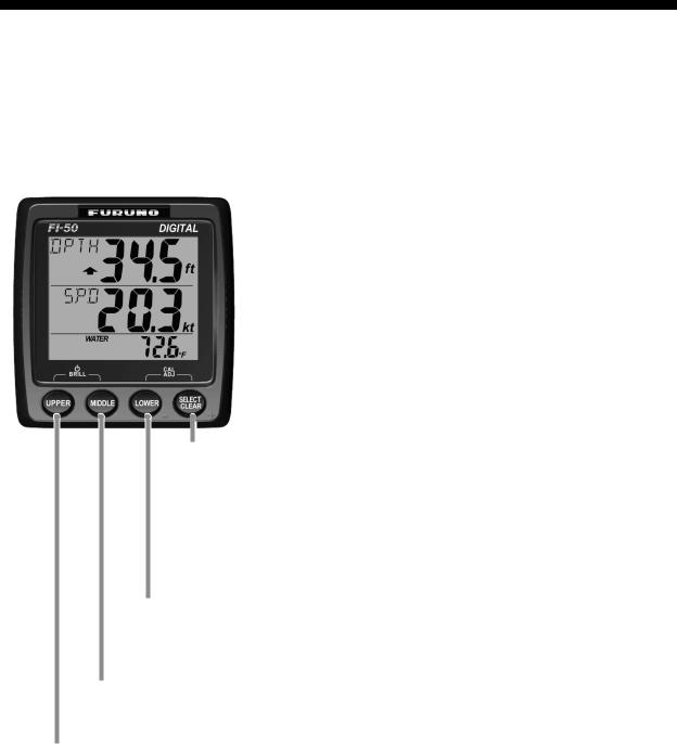
1.1Operating Controls, Display Layout
 UPPER display
(Depth and wind angle information and associated alarms)
 MIDDLE display
(Boat speed and wind speed information and associated alarms)
 LOWER display
(Environmental information, timer alarms, distance counters)
SELECT/CLEAR
-Select menu option.
-Select apparent or true wind.
-Silence alarm.
-Clear data.
-Reset counters and indications.
-Increment value.
LOWER
-Select data for lower display.
-Decrement value.
MIDDLE
Select data for middle display.
UPPER
-Turn on power.
-Select data for upper display.
1
1. OPERATION
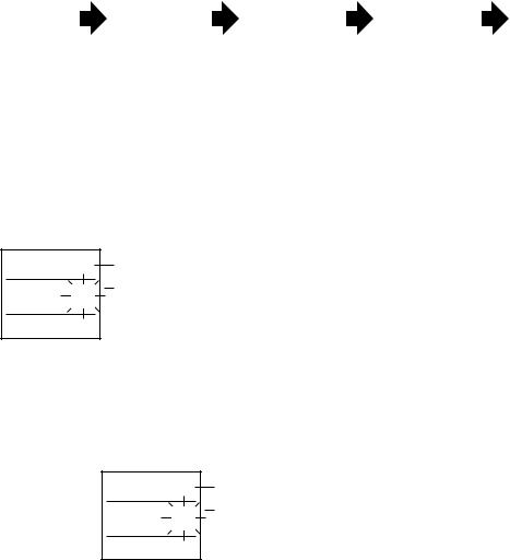
1.2Turning the Power On/Off
To power the instrument, press the UPPER key. All LCD segments go on and off and then the last-used display appears.
To power off the instrument, press the UPPER and MIDDLE keys together. The timer appears and counts down from three seconds to one second, and then the power goes off.
Press UPPER and MIDDLE keys together
|
OFF |
|
|
OFF |
|
|
|
OFF |
|
|
|
3 |
|
|
|
2 |
|
|
|
1 |
|
|
|
|
|
|
|
|
|
|
|
|
POWER
OFF
Power OFF sequence
1.3Adjusting Brilliance and Contrast
1.Press the UPPER and MIDDLE keys together. The display for adjustment of brilliance appears, with current brilliance setting flashing.
brL |
2 |
brl=brilliance
Brilliance setting (flashing)
2.Within seven seconds of completing step 1, press the LOWER key to lower the brilliance, or the SELECT/CLEAR key to raise it.
3.Press the UPPER and MIDDLE keys together. The display for adjustment of contrast appears, with current contrast setting flashing.
CON
3 |
CON=Contrast
Contrast setting (flashing)
4.Within seven seconds of completing step 3, press the LOWER key to lower the contrast, or the SELECT/CLEAR key to raise it.
5.Press the UPPER and MIDDLE keys together to save the settings and restore normal operation.
The brilliance and contrast will be the same on all units which are synchronized. (For how to synchronize instruments, see page 24.)
2
1. OPERATION
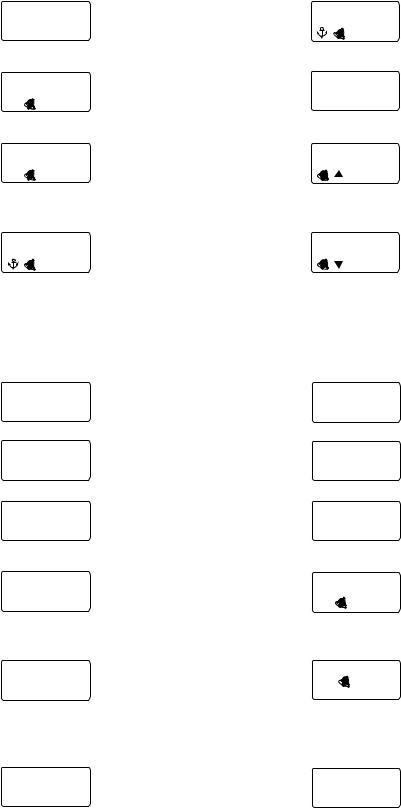
1.4Selecting a Display
Use the UPPER, MIDDLE and LOWER keys to select the item to display in the upper, middle and lower displays.
Current depth
DPTH
Low apparent |
ANG |
|
|
|
50m |
|
|
|
|
||
180° |
|
|
|
|
DPTH |
Shallow |
|
|
|||
wind angle |
APP |
|
|
|
|
|
|
||||
|
|
|
UPPER |
SHALLOW 020m alarm |
|
|
|||||
alarm |
|
|
|
|
|
|
|
|
|||
High apparent ANG |
150° |
- Depth information |
DEEP |
Deep |
|
|
|||||
wind angle |
|
|
|
||||||||
alarm |
APP |
|
|
|
|
|
|
DPTH |
150m alarm |
|
|
|
|
|
- Depth alarms |
|
|
|
|||||
|
|
|
|
- Wind angle info |
|
Shallow anchor |
|
||||
Wind |
ANG |
|
- Wind angle alarms SHALLOWDPTH |
|
|||||||
angle |
APP 150° - Anchor alarms |
010m alarm |
|
|
|||||||
|
|
|
|
|
DPTH |
|
|
|
|
|
|
|
|
|
|
|
DEEP 020m |
|
|
|
|
||
|
|
|
|
Deep anchor alarm |
|
|
|
||||
|
|
|
|
|
|
|
|
Boat speed |
|
|
|
|
|
|
|
|
|
|
|
SPD |
5.2kt |
|
|
|
|
|
Beaufort |
|
O |
|
|
MAX |
|||
|
|
|
|
|
SPD |
|
|||||
|
|
|
wind speed BFT |
|
MAX 10.2kt STW* |
||||||
|
|
|
Low true wind WSPD |
|
|
SPD |
AVG |
||||
|
|
|
speed alarm |
TRU |
5.1kt |
|
|
||||
|
|
|
LO |
MIDDLE |
AVG |
6.8kt STW |
|||||
|
|
|
|
|
|
|
|
||||
|
|
Max. true wind WSPD |
|
|
|
|
|
||||
|
|
speed alarm |
|
TRU |
5.1kt |
|
|
SOG |
|||
|
|
|
MAX |
- Boat speed information |
6.2kt SOG* |
||||||
|
|
|
|
|
|
|
|
||||
|
|
|
Max. true |
WSPD |
- Wind speed information |
|
|||||
|
|
|
- Wind speed alarms |
|
MAX |
||||||
|
|
|
|
TRU |
5.8kt |
SOG |
|||||
|
|
|
wind speed MAX |
|
|
||||||
|
|
|
|
|
|
|
|
|
|
MAX |
6.2kt SOG |
|
|
|
|
|
Wind |
TRUWSPD |
|
|
|
AVG |
|
|
|
|
|
|
speed |
3.8kt |
SOG |
||||
*SOG=Speed Over Ground |
|
|
|
AVG |
6.2kt SOG |
||||||
|
|
VMG |
5.2kt |
|
|
||||||
STW=Speed Thru Water |
|
|
VMG* to windward |
|
|
||||||
VMG=Velocity Made Good |
|
|
|
|
|||||||
|
|
|
|
|
|
||||||
|
|
|
Log distance |
|
Scrolling speed and |
||||||
|
|
|
|
|
|
|
|
|
|
scrolling direction |
|
|
|
|
|
LOG 18432nm |
|
|
Dewpoint |
|
13.1°c |
|
|
Trip |
|
DEWPOINT |
|
TRIP |
50nm distance |
|||
|
|
|||||
Wind |
|
|
|
|
|
Count-up |
Chill CHILL 2.0 °c |
|
|
LOWER |
TIMER 00.0 timer |
||
|
|
|
|
|
|
Count- |
Humidity HUMID |
60 % |
- Environmental info |
TIMER 15:00.0 down |
|||
|
|
|
- Timer alarms |
timer1 |
||
Air AIR PRESS |
|
- Distance counters |
Count- |
|||
pressure |
1000 |
|
|
|
TIMER 15:00.0 down |
|
|
|
|
|
|
|
timer2 |
|
Air |
AIR |
|
|
WATER |
Water |
|
|
|
°c temperature |
|||
temperature |
17.4 |
°c |
20.2 |
|||
Scrolling speed and direction can be changed by the length of key push.
Short push: Scroll in forward order.
Medium push: Go back one display. Several beeps sound and then previous display appears.
Hold down: Rapid scrolling, in forward direction. Several beeps sound and then speed is changed.
3
1. OPERATION
Upper display
|
Display |
Function |
|
|
Display |
Function |
|||||||
|
DPTH |
|
|
Current depth, in meters, |
|
|
DPTH |
|
|
Set deep anchor alarm. |
|||
|
50m |
feet or fathoms. |
|
|
020m |
The alarms are released |
|||||||
|
|
|
|
|
DEEP |
||||||||
|
|
|
|
|
|
|
|
|
when depth goes higher |
||||
|
|
|
|
|
|
|
|
|
|
|
|
|
than threshold value. |
|
DPTH |
|
|
Set shallow alarm. The |
|
|
ANG |
|
|
Apparent (or true) wind |
|||
|
020m |
alarms are released |
|
|
150° |
|
angle, in degrees. |
||||||
|
SHALLOW |
|
|
APP |
|
||||||||
|
|
|
when depth goes lower |
|
|
|
|
|
|
|
|||
|
|
|
|
|
than threshold value. |
|
|
|
|
|
|
|
|
|
DPTH |
|
|
Set deep alarm. Alarms |
|
|
ANG |
|
|
Set high apparent wind |
|||
|
150m |
released when depth |
|
|
150° |
|
angle alarm. The alarms |
||||||
|
DEEP |
|
|
|
APP |
|
|||||||
|
|
|
goes higher than thresh- |
|
|
|
|
|
|
are released when wind |
|||
|
|
|
|
|
|
|
|
||||||
|
|
|
|
|
old value. |
|
|
|
|
|
|
|
angle goes higher than |
|
|
|
|
|
|
|
|
|
|
|
|
|
threshold value. |
|
DPTH |
|
|
Set shallow anchor |
|
|
ANG |
|
|
Set low apparent wind |
|||
|
010m |
alarm. The alarms are |
|
|
180° |
|
angle alarm. The alarms |
||||||
|
SHALLOW |
|
|
APP |
|
||||||||
|
|
|
released when depth |
|
|
|
|
|
|
are released when wind |
|||
|
|
|
|
|
|
|
|
||||||
|
|
|
|
|
goes lower than thresh- |
|
|
|
|
|
|
|
angle goes lower than |
|
|
|
|
|
old value. |
|
|
|
|
|
|
|
threshold value. |
|
|
|
Middle display |
|
|
|
|
|
|
|
|
||
|
|
|
|
|
|
|
|
|
|
|
|||
|
Display |
Function |
|
|
|
Display |
Function |
||||||
|
SPD |
|
5.2kt |
Boat speed, in kt or m/s. |
|
|
|
|
|
5.2kt |
|
Velocity made good. |
|
|
|
|
|
|
|
|
|
|
|
||||
|
|
|
|
|
|
VMG |
|
|
|||||
|
|
|
|
|
|
|
|
|
|
|
|
|
|
|
SPD |
|
|
|
Maximum boat speed. |
|
|
WSPD |
Apparent (or true) wind |
||||
|
10.2kt |
|
Resettable with the |
|
|
speed. |
|||||||
|
MAX |
|
SELECT/CLEAR key. |
|
|
APP |
3.8kt |
|
|||||
|
|
|
|
|
|
|
|
|
|
|
|
|
|
|
SPD |
|
|
|
Average boat speed. |
|
|
WSPD |
Maximum true wind |
||||
|
|
6.8kt |
Resettable with the |
|
|
speed. Resettable with |
|||||||
|
AVG |
|
SELECT/CLEAR key. |
|
|
TRU |
5.8kt |
the SELECT/CLEAR |
|||||
|
|
|
|
MAX |
|||||||||
|
|
|
|
|
|
|
|
|
|
|
|
|
key. |
|
SOG |
|
|
Speed over ground. |
|
|
TRU |
|
|
Set maximum true wind |
|||
|
|
|
|
|
|
|
|
speed alarm. The alarms |
|||||
|
6.2kt |
|
|
|
WSPD |
|
|||||||
|
|
|
|
|
|
MAX |
5.1kt |
are released when true |
|||||
|
|
|
|
|
|
|
|
|
|
|
|
|
wind speed is higher than |
|
|
|
|
|
|
|
|
|
|
|
|
|
threshold value. |
|
SOG |
|
|
Maximum speed over |
|
|
WSPD |
Set low true wind speed |
|||||
|
6.2kt |
ground. Resettable with |
|
|
alarm. The alarms are |
||||||||
|
MAX |
|
the SELECT/CLEAR key. |
|
|
TRULO |
5.1kt |
released when true wind |
|||||
|
|
|
|
|
|
|
|
|
|
|
|
|
speed is lower than |
|
|
|
|
|
|
|
|
|
|
|
|
|
threshold value. |
|
|
|
|
|
|
|
|
|
|
|
|
|
|
|
SOG |
|
|
Average speed over |
|
|
BFT O |
Beaufort wind speed. |
|||||
|
6.2kt |
ground. Resettable with |
|
|
Beaufort speeds up to 12 |
||||||||
|
AVG |
|
|
|
|||||||||
|
|
the SELECT/CLEAR key. |
|
|
are shown. See the table |
||||||||
|
|
|
|
|
|
|
|
|
|
|
|
|
at the top of the next |
|
|
|
|
|
|
|
|
|
|
|
|
|
page for Beaufort no. and |
|
|
|
|
|
|
|
|
|
|
|
|
|
wind speed. |
|
|
|
|
|
|
|
|
|
|
|
|
|
|
4

|
|
|
|
|
|
|
|
|
1. OPERATION |
|
|
|
|
Beaufort no. and wind speed |
|
|
|
||||
|
|
|
|
|
|
|
|
|
|
|
Beaufort |
|
Wind speed |
Beaufort |
|
Wind speed |
|
||||
|
|
|
|
|
|
|
|
|||
no. |
|
|
|
|
|
no. |
|
|
|
|
|
kt |
|
m/s |
kt |
|
m/s |
|
|||
|
|
|
|
|
|
|||||
|
|
|
|
|
|
|
|
|
|
|
0 |
|
0 |
|
0-0.2 |
|
7 |
28-33 |
|
14.4-17.4 |
|
|
|
|
|
|
|
|
|
|
|
|
1 |
|
1-3 |
|
0.5-2.0 |
|
8 |
34-40 |
|
17.5-21.0 |
|
|
|
|
|
|
|
|
|
|
|
|
2 |
|
4-6 |
|
2.1-3.5 |
|
9 |
41-47 |
|
21.1-24.6 |
|
|
|
|
|
|
|
|
|
|
|
|
3 |
|
7-10 |
|
3.6-5.6 |
|
10 |
48-55 |
|
24.7-28.8 |
|
|
|
|
|
|
|
|
|
|
|
|
4 |
|
11-16 |
|
5.7-8.6 |
|
11 |
56-63 |
|
28.9-32.6 |
|
|
|
|
|
|
|
|
|
|
|
|
5 |
|
17-21 |
|
8.7-11.2 |
|
12 |
64 |
|
32.7-32.9 |
|
|
|
|
|
|
|
|
|
|
|
|
6 |
|
22-27 |
|
11.3-14.3 |
|
|
|
|
|
|
|
|
|
|
|
|
|
|
|
|
|
Lower display
Display |
Function |
Display |
Function |
||
|
|
|
|
|
|
|
|
Log distance, up to |
|
|
Air temperature, in °C or |
LOG 18432nm |
99,999 nm. |
AIR |
|
°F. |
|
|
17.4 °c |
|
|||
|
|
|
|
|
|
|
|
Trip distance, up to 999 |
AIR PRESS |
Air pressure, in hecto- |
|
|
50nm |
nm. Resettable with the |
pascals. |
||
|
1000 |
||||
TRIP |
SELECT/CLEAR key. |
|
|||
|
|
|
|
|
|
|
|
Count-up timer. Counts |
|
|
Relative humidity, in per- |
TIMER |
00.0 |
up, like a stopwatch. |
HUMID |
60 % |
centage. |
|
|
|
|
|
|
|
|
Count-down timer 1. |
|
|
Wind chill temperature, |
TIMER 15:00.0 |
Counts elapsed time. |
CHILL |
2.0 °c |
in °C or °F. |
|
|
|
||||
|
|
|
|
|
|
|
|
Count-down timer 2. |
|
|
Dewpoint. |
TIMER 15:00.0 |
Counts elapsed time, |
DEWPOINT 13.1°c |
|
||
from 99:59.0 |
|
||||
|
|
|
|
|
|
|
|
Water temperature, in °C |
|
|
|
WATER |
|
or °F. |
|
|
|
20.2 °c |
|
|
|
|
|
|
|
|
|
|
|
5

1. OPERATION
1.5Selecting Apparent or True Wind Angle, Wind Speed
You can show wind angle and wind speed in apparent or true wind. The apparent wind is the actual flow of air acting upon a sail, or the wind as it appears to the sailor. True wind is the wind seen by a stationary observer in velocity and direction.
With a wind angle or wind speed indication displayed, long-push the SELECT/CLEAR key to change the wind angle or wind speed to apparent and true alternately. A beep sounds after the change is completed. (Wind angle and wind speed displays are mutually changed.) True wind requires boat speed input. If there is no speed input, three dashes appear.
WSPD |
|
ANG |
|
APP |
HI |
APP |
HI |
|
|
||
5.0kt |
135 |
||
SELECT |
SELECT |
||
CLEAR |
CLEAR |
||
WSPD |
|
ANG |
|
TRU |
HI |
TRU |
HI |
9.6kt |
157 |
||
Apparent and true |
Apparent and true |
||
wind speeds |
wind angles |
||
6
Loading...