


 Loading...
OPERATOR'S MANUAL
MONITOR UNIT
MODEL MU-190
www.furuno.com

(Elemental Chlorine Free)
The paper used in this manual is elemental chlorine free.
FURUNO Authorized Distributor/Dealer
|
|
|
|
|
( ) |
A |
: MAY 2011 |
||
|
||||
A1 |
: JUL. 5, 2011 |
|||
|
|
|||
Printed in Japan
Pub. No. OMC-44670-A1
( YOTA) MU-190

IMPORTANT NOTICES
General
•This manual has been authored with simplified grammar, to meet the needs of international users.
•The operator of this equipment must read and follow the descriptions in this manual. Wrong operation or maintenance can cancel the warranty or cause injury.
•Do not copy any part of this manual without written permission from FURUNO.
•If this manual is lost or worn, contact your dealer about replacement.
•The contents of this manual and equipment specifications can change without notice.
•The example screens (or illustrations) shown in this manual can be different from the screens you see on your display. The screens you see depend on your system configuration and equipment settings.
•Save this manual for future reference.
•Any modification of the equipment (including software) by persons not authorized by FURUNO will cancel the warranty.
•All brand and product names are trademarks, registered trademarks or service marks of their respective holders.
How to discard this product
Discard this product according to local regulations for the disposal of industrial waste. For disposal in the USA, see the homepage of the Electronics Industries Alliance (http://www.eiae.org/) for the correct method of disposal.
How to discard a used battery
Some FURUNO products have a battery(ies). To see if your product has a battery, see the chapter on Maintenance. Follow the instructions below if a battery is used. Tape the + and - terminals of battery before disposal to prevent fire, heat generation caused by short circuit.
In the European Union
The crossed-out trash can symbol indicates that all types of batteries must not be discarded in standard trash, or at a trash site. Take the
used batteries to a battery collection site according to your national 
 Cd legislation and the Batteries Directive 2006/66/EU.
In the USA
The Mobius loop symbol (three chasing arrows) indicates that Ni-Cd |
|
|
and lead-acid rechargeable batteries must be recycled. Take the used |
|
|
batteries to a battery collection site according to local laws. |
Ni-Cd |
Pb |
|
In the other countries
There are no international standards for the battery recycle symbol. The number of symbols can increase when the other countries make their own recycle symbols in the future.
i

SAFETY INSTRUCTIONS
Read these safety instructions before you operate the equipment.
WARNING |
Indicates a condition that can cause death or serious |
|
injury if not avoided. |
|
|
CAUTION |
Indicates a condition that can cause minor or moderate |
|
injury if not avoided. |
|
|
Warning, Caution |
Prohibitive Action |
Mandatory Action |
Safety Instructions for the Operator
 WARNING
Immediately turn off the power at the switchboard if water leaks into the equipment or something is dropped into the equipment.
Continued use of the equipment can cause fire or electrical shock. Contact a FURUNO agent for service.
Immediately turn off the power at the switchboard if the equipment is emitting smoke or fire.
Continued use of the equipment can cause fire or electrical shock. Contact a FURUNO agent for service.
Do not disassemble or modify the equipment.
Fire, electrical shock or serious injury can result.
Turn off the power immediately if you feel the equipment is behaving abnormally.
Turn off the power at the switchboard if the equipment becomes abnormally warm or is emitting odd noises. Contact a FURUNO dealer or agent for advice.
 WARNING
Use the proper fuse.
Use of a wrong fuse can cause fire or damage to the equipment.
Do not place any object near the exhaust or intake vent.
Fire may result.
 CAUTION
Do not connect/disconnect the signal cable while turning the power on.
The unit may be damaged.
Handle the LCD monitor with care.
The face of the LCD monitor is made of glass. Injury may result if the glass breaks.
ii

Safety Instructions for the Installer
 WARNING
Turn off the power at the switchboard before beginning the installation.
Fire or electrical shock can result if the power is left on.
Do not install the equipment where it may get wet from rain or water splash.
Water in the equipment can result in fire, electrical shock or damage to the equipment.
SAFETY INSTRUCTIONS
 CAUTION
Observe the following compass safe distances to prevent interference to a magnetic compass:
|
Standard |
Steering |
|
compass |
compass |
MU-190 |
1.65 m |
1.05 m |
|
|
|
About the TFT LCD
The TFT LCD is constructed using the latest LCD techniques, and displays 99.99% of its pixels. The remaining 0.01% of the pixels may drop out or blink, however this is not an indication of malfunction.
iii

TABLE OF CONTENTS
Note: This manual contains both English and Japanese instructions. The Installation
Materials, Outline Drawings, and Interconnection Diagram are located at the back of this manual.
FOREWORD ................................................................................................................. |
v |
||
SYSTEM CONFIGURATION ....................................................................................... |
vi |
||
EQUIPMENT LISTS.................................................................................................... |
vii |
||
1. |
MOUNTING, WIRING............................................................................................. |
1 |
|
|
1.1 |
Preparation................................................................................................................. |
1 |
|
1.2 |
Flush Mount, Fixed at Front ....................................................................................... |
2 |
|
1.3 |
Flush Mount, Fixed at Front, with Hood ..................................................................... |
3 |
|
1.4 |
Flush Mount, Fixed at Rear........................................................................................ |
5 |
|
1.5 |
Flush Mount, Fixed at Rear, with Hood...................................................................... |
7 |
|
1.6 |
Tabletop Mount .......................................................................................................... |
8 |
|
1.7 |
Flush Mount a Series Side by Side .......................................................................... |
10 |
|
1.8 |
Wiring ....................................................................................................................... |
11 |
2. |
ADJUSTMENTS................................................................................................... |
12 |
|
|
2.1 |
Installation Settings .................................................................................................. |
12 |
|
2.2 |
RGB/DVI Setting (For Non-SOLAS)......................................................................... |
14 |
|
2.3 |
Video Composite Signal Setting (For Non-SOLAS) ................................................. |
16 |
|
2.4 |
The Menu Window Setting (For Non-SOLAS) ......................................................... |
17 |
|
2.4.1 How to adjust the menu window ....................................................................... |
17 |
|
|
2.4.2 How to change the signal name ....................................................................... |
18 |
|
3. |
OPERATION ........................................................................................................ |
19 |
|
|
3.1 |
Controls.................................................................................................................... |
19 |
|
3.2 |
How to Turn the Power On/Off................................................................................. |
19 |
|
3.2.1 Turn the power on/off........................................................................................ |
19 |
|
|
3.2.2 Unlock the key operation .................................................................................. |
20 |
|
|
3.3 |
How to Adjust the Display Brilliance......................................................................... |
20 |
|
3.4 |
How to Select the Source for Main Picture .............................................................. |
21 |
|
3.5 |
How to Display the PIP Window............................................................................... |
21 |
|
3.6 |
SYSTEM Menu ........................................................................................................ |
21 |
|
3.6.1 How to set the auto dimmer.............................................................................. |
21 |
|
|
3.6.2 How to clear the memory.................................................................................. |
22 |
|
4. |
MAINTENANCE, TROUBLESHOOTING............................................................. |
23 |
|
|
4.1 |
Maintenance............................................................................................................. |
23 |
|
4.2 |
Troubleshooting ....................................................................................................... |
24 |
|
4.3 |
Parts Location and Parts List ................................................................................... |
24 |
SPECIFICATIONS .................................................................................................. |
SP-1 |
||
INSTALLATION MATERIALS .................................................................................. |
A-1 |
||
OUTLINE DRAWINGS.............................................................................................. |
D-1 |
||
INTERCONNECTION DIAGRAM .............................................................................. |
S-1 |
||
Declaration of Conformity |
|
||
iv

FOREWORD
A Word to the Owner of the MU-190
FURUNO Electric Company thanks you for purchasing the MU-190 19” Monitor Unit. We are confident you will discover why the FURUNO name has become synonymous with quality and reliability.
For over 60 years FURUNO Electric Company has enjoyed an enviable reputation for quality and reliability throughout the world. This dedication to excellence is furthered by our extensive global network of agents and dealers.
Your equipment is designed and constructed to meet the rigorous demands of the marine environment. However, no machine can perform its intended function unless properly installed and maintained. Please carefully read and follow the operation, installation and maintenance procedures set forth in this manual.
We would appreciate feedback from you, the end-user, about whether we are achieving our purposes.
Thank you for considering and purchasing FURUNO.
Features
The main features of the MU-190 are as shown below.
•Selectable screen from RGB (1 port), Digital (2 ports) or Composite (1 port).
•Main or remote display for radars, video sounders, sonars, plotter. For the connectable equipment, see the SYSTEM CONFIGURATION on page vi.
•High resolution display of 1280 x 1024 (SXGA)
•Automatic brilliance adjustment by the light sensor.
•Picture-in-picture function
•Power on/off automatically through the DVI signal.
Program
Program Name |
Version |
Date of Change |
|
|
|
APR PROGRAM |
2651020-01.xx |
May. 2011 |
|
|
|
FPGA PROGRAM |
2651021-01.xx |
May. 2011 |
|
|
|
xx: minor change
You can see these program numbers on the [SYSTEM] menu (see section 3.6). To open the [SYSTEM] menu, unlock the key operation (see paragraph 3.2.2).
Note: When you connect the monitor unit to FAR-21x7 series, FEA-2107 or FCR-21x7 series, lock the key operation (see paragraph 3.2.2) after confirming the program numbers.
v

SYSTEM CONFIGURATION
|
|
|
|
|
|
RGB |
FSV-30/30S, etc. |
|
|
|
|
|
|
|
|
DVI (2 ports) |
FAR-21x7, FEA-2107, FCR-21x7, etc. |
|
|
|
|
|
|
|
|
VIDEO (NTSC/PAL) |
CCD camera, DVD recorder, etc. |
|
|
|
|
|
|
|
|
RS-232C |
FEA-2107, FCR-21x7, etc. |
|
|
|
|
|
|
|
MONITOR UNIT |
|
|
||
100-230 VAC MU-190 |
|
Environmental category |
|
|
|
|
MU-190: Protected from the weather |
|
|
|
|
Connectable equipment |
|
|
|
|
|
|
|
Equipment |
|
Resolution |
Signal |
|
|
|
|
|
|
FCV-1200L/1200LM |
|
VGA* |
Analog RGB, via IF-8000 |
|
|
|
|
|
|
FSV-24/24S |
|
SXGA |
Analog RGB |
|
|
|
|
|
|
FSV-30/30S |
|
SXGA |
Analog RGB |
|
|
|
|
|
|
FSV-84/84L |
|
SXGA |
Analog RGB |
|
|
|
|
|
|
FSV-85/85L |
|
SXGA |
Analog RGB |
|
|
|
|
|
|
FCV-30 |
|
SXGA |
Analog RGB |
|
|
|
|
|
|
FAR-21x7 |
|
SXGA |
DVI |
|
|
|
|
|
|
FEA-2107 |
|
SXGA |
DVI |
|
|
|
|
|
|
FCR-21x7 |
|
SXGA |
DVI |
|
|
|
|
|
|
|
|
SVGA* |
|
|
|
|
|
|
|
MFDBB (NAVnet 3D) |
|
XGA* |
DVI |
|
|
|
|
|
|
|
|
SXGA |
|
|
|
|
|
|
|
Note 1: Landscape orientation only.
Note 2: *: When inputting VGA, SVGA or XGA, a circle may be displayed as an ellipse because the aspect ratio differs (see "DISP MODE*" on page 15).
vi

EQUIPMENT LISTS
Standard supply
Name |
Type |
Code No. |
Qty |
Remarks |
Monitor Unit |
MU-190 |
- |
1 |
|
Installation |
CP26-01600 |
000-019-210 |
1 set |
• Installation Materials (CP26-01601, Code |
Materials |
|
|
|
No.: 001-116-250, See page A-1.) |
|
|
|
|
• Cable Assembly (DVI-D/D S-LINK 5M, |
|
|
|
|
Code No.: 001-132-960-10) |
Accessories |
FP26-00401 |
001-080-780 |
1 set |
LCD Cleaning Cloth (19-028-3125, |
|
|
|
|
Code No.: 100-360-671-10) |
Spare Parts |
SP26-00501 |
001-116-240 |
1 set |
Glass Tube Fuse (FGBO 250V 1A PBF, |
|
|
|
|
Code No.: 000-155-828-10) 3 pcs. |
Optional supply
Name |
Type |
Code No. |
Qty |
Remarks |
Cable Assembly |
3COX-2P-6C |
001-077-230-10 |
1 |
Cable length: 5 m (15 pin D-sub |
|
5M |
|
|
connector at both ends) |
|
3COX-2P-6C |
001-077-220-10 |
1 |
Cable length: 10 m (15 pin |
|
10M |
|
|
D-sub connector at both ends) |
|
DVI-D/D |
001-132-960-10 |
1 |
Cable length: 5 m |
|
S-LINK 5M |
|
|
(with DVI-D connector at both |
|
|
|
|
ends) |
|
DVI-D/D |
001-133-980-10 |
1 |
Cable length: 10 m |
|
S-LINK 10M |
|
|
(with DVI-D connector at both |
|
|
|
|
ends) |
Bracket Assembly |
OP26-5 |
000-016-270 |
1 set |
|
(w/knobs) |
|
|
|
|
Hood Assembly |
OP26-6 |
001-080-930 |
1 set |
|
Dust Cover |
26-007-1201 |
001-116-260-10 |
1 |
|
Flush Mount Kit |
OP26-12 |
001-116-280 |
1 set |
• Flush Mounting Sponge H 19 |
|
|
|
|
(26-005-3123, Code No.: |
|
OP26-13 |
001-116-290 |
1 set |
|
|
(Two units |
|
|
100-351-550-10) |
|
installed side |
|
|
• Flush Mounting Sponge V 19 |
|
by side) |
|
|
(26-005-3124, Code No.: |
|
|
|
|
100-351-560-10) |
|
OP26-14 |
001-116-300 |
1 set |
|
|
• Washer Head Screw B |
|||
|
(Three units |
|
|
|
|
|
|
(M4x10, Code No.: 000-163- |
|
|
installed side |
|
|
|
|
|
|
836-10) |
|
|
by side) |
|
|
|
|
|
|
• Flush Mount Fixture 19 |
|
|
|
|
|
|
|
|
|
|
(CP26-01401, Code No.: 001- |
|
|
|
|
080-890) |
|
|
|
|
Note: The quantity of each part |
|
|
|
|
depends on the number of units |
|
|
|
|
connected. |
|
|
|
|
|
Connection Stand (19) |
OP26-20 |
001-139-300 |
1 set |
|
Bracket Assembly |
OP26-21 |
001-139-310 |
1 set |
|
Hood (19) Assembly |
OP26-24 |
001-139-370 |
1 set |
|
Monitor Replacement |
OP26-22 |
001-139-320 |
1 |
For flush mount |
Kit |
|
|
|
|
OP26-23 |
001-139-360 |
1 |
For tabletop mount |
|
|
OP26-26 |
001-139-390 |
1 |
For hood mount |
vii

1.MOUNTING, WIRING
1.1Preparation
Mounting method
You can install the monitor unit as follows. See the outline drawings at the back of this manual for mounting dimensions.
•Flush mount, fixed at front (standard)
•Flush mount, fixed at front, with hood (option)
•Flush mount, fixed at rear (option)
•Flush mount, fixed at rear, with hood (option)
•Tabletop mount (option, hood-mountable)
•Flush mount a series side by side, fixed at rear
Note 1: The face of the LCD is made of glass. Handle it with care.
Note 2: For flush mount, take care so that the monitor unit does not fall during the installation.
Mounting location
Select a mounting location considering the following points. This equipment is free from electromagnetic fields.
•Make sure the mounting location is strong enough to support the weight of the unit.
•Locate the unit away from direct sunlight. An LCD may darken if it is exposed to direct sunlight for a long time.
•Select a location where the screen can be easily viewed and the controls can be easily operated.
•Leave enough space around the unit for service and maintenance. See the outline drawings at the back of this manual for minimum service clearance.
•Locate the unit away from areas subject to water splash and rain.
•Observe the compass safe distances (see page iii) to prevent interference to a magnetic compass.
Run cables before installing the monitor unit
Run all cables before you install the monitor unit. See the interconnection diagram at the back of this manual.
1
1. MOUNTING, WIRING
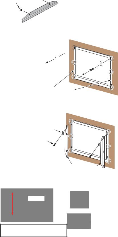
1.2Flush Mount, Fixed at Front
Flush mount, fix at front is the standard installation method.
1.Use the flush mounting template (supplied) to make a cutout in the mounting location.
2.Attach the flush mounting
sponges H19 and V19 to the back of the monitor unit in the order shown in the figure at
right.
Flush Mounting Sponge H19 (5 mm) for top and bottom
Flush Mounting  Sponge V19 (2 mm)

 for left and right
3.Attach the flush mount panels 19 to the monitor unit from the rear with the binding head screws (M4x10, 6 pcs., supplied).
Binding Head Screw
Flush Mount Panel 19
Note: Attach the flush mount panels to both sides of the monitor unit with no gap.
4.Connect all cables at the back of the monitor unit. See section 1.8.
5.Set the monitor unit assembly to the cutout.
6.Fix the monitor unit to the cutout with the self-tapping screws (5x20, 4 pcs., supplied).
Self-Tapping Screw
(4 places)
2

1. MOUNTING, WIRING
7. Set the masking panel to each side of the monitor unit.
Masking Panel for 19” LCD
How to attach or detach the masking panel for 19” LCD
Do the following to attach or detach the masking panel for 19” LCD.
Reverse view of masking panel for 19” LCD
 Tab A
Tab A


 Tab B
Tab B
|
a |
|
b |
|
Front side of |
c |
monitor unit |
|
Set the masking panel for 19” LCD to each side of the monitor unit. Attach each tab A to the monitor unit. Be careful not to break the tabs.
To attach, follow order of right arrow (→). To detach, follow order of left arrow (←).
|
Monitor unit |
|
2 |
|
1 |
2 |
|
|
|
||
|
|
|
|
Masking |
→ |
→ |
1 |
panel |
← |
← |
|
|
|
Set tab B to the edge of the monitor unit.
Attach: Push the masking panel for 19” LCD in the direction
, rotate the panel toward the monitor unit, then set each tab A one by one (three places of a, b and c) .
Detach: Push the masking panel for 19” LCD in the direction 1, then release each tab A one by one (three places of a, b and c) in the direction 2.
1.3Flush Mount, Fixed at Front, with Hood
The flush mount, fixed at front method allows you to attach a hood (19) assembly OP26-24 (option) to the monitor unit.
Hood (19) assembly OP26-24 (Code No.: 001-139-370)
Name |
Type |
Code No. |
Qty |
Hood (19) Assembly |
OP26-6-1 |
001-080-970 |
1 |
Knob M4 |
03-163-2303 |
100-343-602-10 |
4 |
Hood Fixing Plate (19) |
26-007-1128 |
100-366-350-10 |
2 |
Binding Head Screw |
M3x8 |
000-172-166-10 |
6 |
3
1. MOUNTING, WIRING
1.Use the flush mounting template (supplied) to make a cutout in the mounting location.
2.Follow steps 2 to 6 in section 1.2.
3.Loosely fix the knobs (4 pcs.) to the hood fixing plates (19) from inside the plates.
Knob 

 Hood Fixing Plate (19)
4.Remove the binding head screws (M3x5, 6pcs.) and the side panel bases (6 pcs.) from the flush mount panels 19 attached to the monitor unit.
Side Panel Base (6 pcs.) 


Binding Head Screw (6 pcs.)


Flush Mount Panel 19
5.Attach the hood fixing plates (19) and the side panel bases to the right and left sides of the monitor unit with the binding head screws (M3x8, 6pcs.)
Side Panel Base (6 pcs.)
Binding Head Screw (6 pcs.)
Hood Fixing Plate (19)
6.Press and rub folds on the hood with your hands to make creases clearly. The degree of creases should be within 90° when the hood is opened.
Hood
Correct
Improper Press and move your hands to insufficient upward and downward several times.
4
Loading...