


FM-8900S
Table of contents
 Loading...
OPERATOR'S MANUAL
VHF RADIOTELEPHONE
MODEL
FM-8900S
www.furuno.com

9-52 Ashihara-cho,
*
00017619910
**00017619910
*
*
00017619910
**00017619910
*
Nishinomiya, 662-8580, JAPAN
The paper used in this manual
is elemental chlorine free.
・FURUNO Authorized Distributor/Dealer
All rights reserved.
Pub. No. OME-56800-A
(YOTA ) FM-8900S
Printed in Japan
A : APR 2012
* 0 0 0 1 7 6 1 9 9 1 0 *
.
IMPORTANT NOTICES
General
• This manual has been authored with simplified grammar, to meet the needs of international users.
• The operator of this equipment must read and follow the descriptions in this manual. Wrong operation or maintenance can cancel the warranty or cause injury.
• Do not copy any part of this manual without written permission from FURUNO.
• If this manual is lost or worn, contact your dealer about replacement.
• The contents of this manual and equipment specifications can change without notice.
• The example screens (or illustrations) shown in this manual can be different from the screens
you see on your display. The screens you see depend on your system configuration and equipment settings.
• Save this manual for future reference.
• Any modification of the equipment (including software) by persons not authorized by FURUNO
will cancel the warranty.
• All brand and product names are trademarks, registered trademarks or service marks of their
respective holders.
How to discard this product
Discard this product according to local regulations for the disposal of industrial waste. For disposal
in the USA, see the homepage of the Electronics Industries Alliance (http://www.eiae.org/) for the
correct method of disposal.
How to discard a used battery
Some FURUNO products have a battery(ies). To see if your product has a battery, see the chapter
on Maintenance. Follow the instructions below if a battery is used. Tape the + and - terminals of
battery before disposal to prevent fire, heat generation caused by short circuit.
In the European Union
The crossed-out trash can symbol indicates that all types of batteries
must not be discarded in standard trash, or at a trash site. Take the
used batteries to a battery collection site according to your national
legislation and the Batteries Directive 2006/66/EU.
In the USA
The Mobius loop symbol (three chasing arrows) indicates that Ni-Cd
and lead-acid rechargeable batteries must be recycled. Take the
used batteries to a battery collection site according to local laws.
In the other countries
Ni-Cd Pb
Cd
There are no international standards for the battery recycle symbol. The number of symbols can
increase when the other countries make their own recycle symbols in the future.
i
SAFETY INSTRUCTIONS
The user must read the appropriate safety instructions before attempting to install or operate
the equipment.
Indicates a condition that can cause death or serious injury
WARNING
CAUTION
Warning, Caution Prohibitive Action Mandatory Action
if not avoided.
Indicates a condition that can cause minor or moderate
injury if not avoided.
WARNING
Do not open the equipment.
Hazardous voltage which can cause
electrical shock, burn or serious
injury exists inside the equipment.
Only qualified personnel should work
inside the equipment.
Do not approach the antenna
closer than listed below when it
is transmitting.
The antenna emits radio waves that
can be harmful to the human body.
RF power density on
antenna aperture
100 W/m
10 W/m
2 W/m
(MPE: Minimum Permissible Exposure)
Immediately turn off the power at
the switchboard if water leaks into
the equipment or the equipment is
emitting smoke or fire.
Continued use of the equipment can
cause fire or electrical shock. Contact
a FURUNO agent for service.
Do not disassemble or modify the
equipment.
Fire, electrical shock or serious injury
can result.
Do not place liquid-filled containers
on the top of the equipment.
Fire or electrical shock can result if a
liquid spills into the equipment.
2
2
2
Distance
0.12 m
0.39 m
0.89 m
Description
required by
IEC 60945
IEC 60945
MPE by FCC
WARNING
Do not operate the equipment with
wet hands.
Electrical shock can result.
Turn off the power immediately if you
feel the equipment is behaving
abnormally.
Turn off the power at the switchboard if
the equipment becomes abnormally
warm or is emitting odd noises. Contact
a FURUNO dealer or agent for advice.
Make sure no rain or water splash
leaks into the equipment.
Fire or electrical shock can result if
water leaks in the equipment.
Use the proper fuse.
Use of the wrong fuse can cause fire or
electrical shock.
Any repair work must be done by a
licensed radio technician.
Improper repair work can cause fire or
electrical shock.
Do not operate the [DISTRESS] key
except in case of a life-endangering
situation on your vessel.
Operating the [DISTRESS] key
transmits the distress alert. Accidental
transmission may prevent search and
rescue operations for actual emergency.
If the distress alert is accidentally
transmitted, contact the nearest station
to cancel the alert.
ii
SAFETY INSTRUCTIONS
CAUTION
If the distress alert is accidentally
transmitted, contact the nearest
coast station and inform them of the
accidental
following data:
a) Ship's name
b) Ship's call sign and DSC number
c) Position at time of transmission
d) Time of transmission
transmission, providing the
Do not touch any part of the
antenna when the equipment is
transmitting.
Electrical shock can result.
Do not apply strong pressure to
the LCD, which is made of glass.
Injury can result if the LCD breaks.
CAUTION
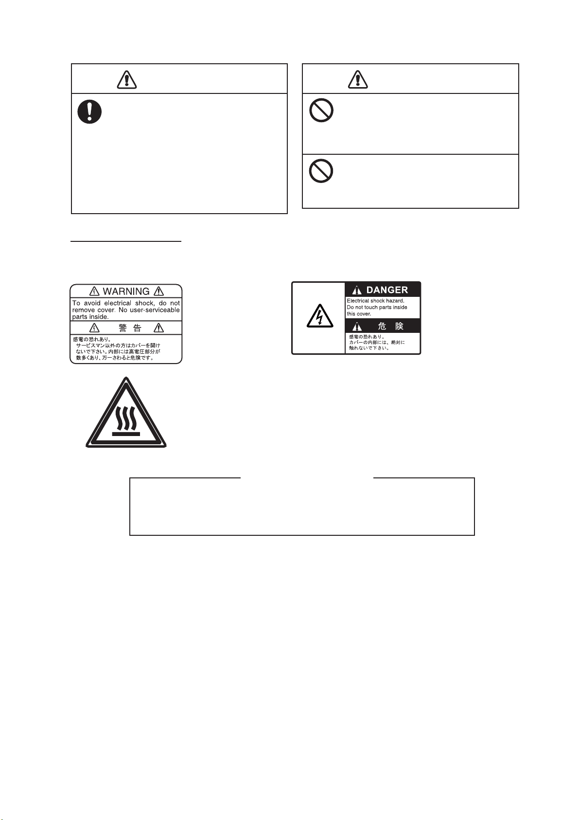
WARNING LABELS
Warning labels are attached to the equipment. Do not remove any label. If a label is missing or
damaged, contact a FURUNO agent or dealer about replacement.
Name: Warning Label 1
Type: 86-003-1011-3
Code No.: 100-236-233-10
Name: Warning Label
Type: 14-055-4202-1
Code No.: 100-245-221-10
Name: High Temp Warning Label
Type: 05-089-2142-0
Code No.: 100-301-620-00
About the TFT LCD
The TFT LCD is constructed using the latest LCD techniques, and displays
99.99% of its pixels. The remaining 0.01% of the pixels may drop out or
blink, however this is not an indication of malfunction.
iii
DISTRESS ALERT
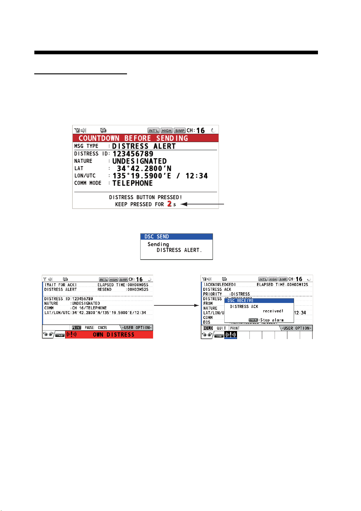
How to send a distress alert
Below is the procedure for transmitting a distress alert via radiotelephone. Transmit the distress
alert when a life-endangering situation occurs on your vessel.
1. Open the DISTRESS key cover then press and hold the DISTRESS key for four seconds. The
following screen appears.
Countdown message
2. When the message "Sending DISTRESS ALERT." appears on the screen, release the DISTRESS key. The audio alarm sounds for two seconds.
After the distress alert has been sent, the following screens appear in order.
When distress
acknowledge
call is received
by coast station
3. The audio alarm sounds. Press the CANCEL key to silence the audio alarm.
4. Communicate with the coast station via radiotelephone (CH16) as below.
a) Say “MAYDAY” three times.
b) Say “This is ...” name of your ship and call sign three times.
c) Give nature of distress and assistance needed.
d) Give description of your ship (type, color, number of persons onboard, etc.).
Note: If you do not receive the distress alert acknowledge call, the equipment automatically retransmits the distress alert after 3 min 30 seconds to 4 min 30 seconds. Then the equipment
awaits the distress alert acknowledge call. This is repeated until the distress alert is acknowledged.
iv

DISTRESS ALERT
How to cancel the distress alert
You can cancel the distress alert while it is being sent or while waiting for its acknowledgement as
follows.
1. Rotate the CHANNEL/ENTER knob to select [CANCEL] in the user options area then push
the knob.
The following message appears on the screen.
2. Rotate the CHANNEL/ENTER knob to select [Yes] then push the knob to send the distress
cancel call on CH70. After transmitting the distress cancel call, the following message appears on the screen.
3. Push the CHANNEL/ENTER knob to erase the message. The following message appears on
the screen.
4. Communicate with all ships via radiotelephone referring to the message at step 3.
5. Push the CHANNEL/ENTER knob. The following message appears on the screen.
6. With [Finish] selected, push the CHANNEL/ENTER knob.
v

TABLE OF CONTENTS
FOREWORD ...................................................................................................................ix
SYSTEM CONFIGURATION ..........................................................................................xi
1. OPERATIONAL OVERVIEW .................................................................................1-1
1.1 Controls ...................................................................................................................... 1-1
1.2 How to Turn On/Off the Power...................................................................................1-2
1.3 Radiotelephone (RT) Screen .....................................................................................1-2
1.4 How to Adjust the Brilliance of the Display and Panel ............................................... 1-3
1.5 How to Select the Channel Region, Channel.............................................................1-3
1.6 Transmission.............................................................................................................. 1-4
1.7 How to Turn On/Off the Loudspeaker ........................................................................1-5
1.8 Quick Selection of CH16 ............................................................................................ 1-5
1.9 How to Scan Dual Channels (DW).............................................................................1-5
1.10 How to Scan All Channels.......................................................................................... 1-6
1.11 How to Set the Auto Acknowledgement.....................................................................1-7
1.12 Priority of the System ................................................................................................. 1-7
1.13 Intercom ..................................................................................................................... 1-8
1.14 Operation of Session.................................................................................................. 1-9
1.15 Replay Function ....................................................................................................... 1-12
2. DSC OVERVIEW....................................................................................................2-1
2.1 What is DSC?............................................................................................................. 2-1
2.2 DSC Messages .......................................................................................................... 2-1
2.3 Audio Alarms.............................................................................................................. 2-2
2.4 Description of Call Screens........................................................................................2-3
2.4.1 RX calls .......................................................................................................... 2-3
2.4.2 TX calls .......................................................................................................... 2-4
3. DSC DISTRESS OPERATIONS ............................................................................3-1
3.1 How to Send a Distress Alert ..................................................................................... 3-1
3.1.1 How to send a distress alert by DISTRESS key with distress information
not edited ....................................................................................................... 3-1
3.1.2 How to send a distress alert by DISTRESS key with distress information
edited ............................................................................................................. 3-3
3.2 How to Receive a Distress Alert................................................................................. 3-4
3.3 How to Send a Distress Relay on Behalf of a Ship in Distress ................................ 3-10
3.3.1 How to send a distress relay to a coast station............................................ 3-10
3.3.2 How to send a distress relay to all ships...................................................... 3-11
3.4 How to Receive a Distress Relay............................................................................. 3-13
3.5 How to Cancel the Distress Alert ............................................................................. 3-13
4. DSC GENERAL MESSAGE CALLING, RECEIVING............................................4-1
4.1 Individual Call.............................................................................................................4-1
4.1.1 How to send an individual call........................................................................4-1
4.1.2 How to receive an individual call .................................................................... 4-4
4.2 Group Call ..................................................................................................................4-6
4.2.1 How to send a group call................................................................................ 4-6
4.2.2 How to receive a group call............................................................................ 4-7
4.3 PSTN Call .................................................................................................................. 4-8
4.3.1 How to send a PSTN call ...............................................................................4-8
4.3.2 How to receive a PSTN call ......................................................................... 4-10
4.3.3 Note after sending a PSTN call.................................................................... 4-10
vi

TABLE OF CONTENTS
4.4 All Ships Call ............................................................................................................4-11
4.4.1 How to send an all ships call........................................................................4-11
4.4.2 How to receive an all ships call ....................................................................4-12
4.5 Position Call..............................................................................................................4-13
4.5.1 How to request other ship's position.............................................................4-13
4.5.2 Other ship requests your position.................................................................4-15
4.6 How to Receive a Polling Request ...........................................................................4-15
4.6.1 Automatic reply.............................................................................................4-15
4.6.2 Manual reply.................................................................................................4-16
4.7 Neutral Craft Call ......................................................................................................4-16
4.7.1 How to send a neutral craft call....................................................................4-16
4.7.2 How to receive a neutral craft call ................................................................4-17
4.8 Medical Transport Call..............................................................................................4-18
4.8.1 How to send a medical transport call ...........................................................4-18
4.8.2 How to receive a medical transport call........................................................4-19
5. MENU OPERATION ..............................................................................................5-1
5.1 How to Open/Close the MENU Screen ......................................................................5-1
5.2 Handset Volume Setting.............................................................................................5-2
5.3 Channel Setting..........................................................................................................5-2
5.3.1 Channel region...............................................................................................5-2
5.3.2 Memory ..........................................................................................................5-2
5.4 Memory Configuration ................................................................................................5-3
5.5 How to Print Messages...............................................................................................5-4
5.6 Position Setting...........................................................................................................5-4
5.7 Date and Time Setting................................................................................................5-5
5.8 Timeout Setting ..........................................................................................................5-5
5.9 How to Name the Terminal for Intercom.....................................................................5-6
5.10 Automatic Switch to CH16 ..........................................................................................5-7
5.11 External Alarm Setting ................................................................................................5-7
5.12 RT Application Setting ................................................................................................5-8
5.13 Address Book .............................................................................................................5-8
5.13.1 List for address data.......................................................................................5-8
5.13.2 How to register addresses..............................................................................5-9
5.13.3 How to edit addresses..................................................................................5-10
5.13.4 How to delete addresses..............................................................................5-11
5.13.5 How to create a DSC message with registered address..............................5-11
5.14 TX Message Preparation..........................................................................................5-12
5.14.1 List for message files....................................................................................5-12
5.14.2 Individual calls ..............................................................................................5-13
5.14.3 Group calls ...................................................................................................5-14
5.14.4 PSTN calls....................................................................................................5-15
5.14.5 Test calls ......................................................................................................5-15
5.14.6 How to edit prepared messages...................................................................5-16
5.14.7 How to send prepared messages.................................................................5-16
5.14.8 How to delete prepared messages...............................................................5-17
5.15 Log File.....................................................................................................................5-17
5.15.1 How to open a log file...................................................................................5-17
5.15.2 How to delete log files ..................................................................................5-18
5.16 How to Set the AUTO ACK Details...........................................................................5-19
5.17 Special Messages ....................................................................................................5-20
5.18 Propose Channel Setting..........................................................................................5-20
5.19 Sound Setting...........................................................................................................5-20
5.20 Alarm Lists................................................................................................................5-21
vii

TABLE OF CONTENTS
6. REMOTE HANDSET..............................................................................................6-1
6.1 Controls ...................................................................................................................... 6-1
6.2 How to Turn On/Off the Power...................................................................................6-2
6.3 Radiotelephone (RT) Screen .....................................................................................6-2
6.4 How to Adjust the Brilliance and Contrast .................................................................. 6-3
6.5 How to Select the Channel Region, Channel.............................................................6-3
6.6 Transmission.............................................................................................................. 6-4
6.7 How to Turn On/Off the Loudspeaker ........................................................................ 6-5
6.8 Quick Selection of CH16 ............................................................................................ 6-5
6.9 Intercom .....................................................................................................................6-5
6.10 How to Change the Terminal ID................................................................................. 6-6
6.11 Audio setting .............................................................................................................. 6-6
6.12 How to Test FM-8900S from a Remote Handset....................................................... 6-8
6.13 How to Display the Program Versions ....................................................................... 6-8
6.14 Squelch ...................................................................................................................... 6-8
7. MAINTENANCE & TROUBLESHOOTING ............................................................7-1
7.1 Daily Test ...................................................................................................................7-1
7.2 Maintenance............................................................................................................... 7-2
7.3 Simple Troubleshooting .............................................................................................7-2
7.4 Warning and Caution Messages................................................................................7-3
7.5 Test Call ..................................................................................................................... 7-4
APPENDIX 1 MENU TREE .......................................................................................AP-1
APPENDIX 2 MARINE VHF CHANNEL LISTS ........................................................AP-3
APPENDIX 3 ABBREVIATIONS LIST....................................................................AP-13
APPENDIX 4 DIGITAL INTERFACE (IEC 61162-1)...............................................AP-15
APPENDIX 5 PARTS LIST......................................................................................AP-20
APPENDIX 6 PARTS LOCATION...........................................................................AP-21
SPECIFICATIONS .....................................................................................................SP-1
INDEX..........................................................................................................................IN-1
viii

FOREWORD
A Word to the Owner of the FM-8900S
Congratulations on your choice of the FURUNO FM-8900S VHF Radiotelephone. We are confident you will see why the FURUNO name has become synonymous with quality and reliability.
Since 1948, FURUNO Electric Company has enjoyed an enviable reputation for innovative and
dependable marine electronics equipment. This dedication to excellence is furthered by our extensive global network of agents and dealers.
Your equipment is designed and constructed to meet the rigorous demands of the marine environment. However, no machine can perform its intended function unless properly installed and
maintained. Please carefully read and follow the operation and maintenance procedures set forth
in this manual.
We would appreciate feedback from you, the end-user, about whether we are achieving our purposes.
Thank you for considering and purchasing FURUNO equipment.
Features
The FM-8900S is a cost-effective all-in-one marine VHF radio system consisting of a 25 W VHF
radiotelephone, a DSC modem, and a CH70 watchkeeping receiver. It complies with GMDSS carriage requirements for safety and general communications.
The FM-8900S offers semi-duplex voice communication on ITU channels in the marine mobile
VHF band. The features include Scanning Dual Channels (DW) which allows a continuous watch
on CH16 and another selected frequency.
Data is displayed on a large, easy-to-read color LCD. Operation is simplified by the use of few
keys and easy-to-follow menus.
The built-in DSC function produces and receives digital selective callings for quick and efficient
establishment of distress, urgency, safety and routine communications with other ships and coast
stations that install any VHF DSC facilities.
Full Class-A DSC functions are provided for distress alert transmission and reception, as well as
the general call formats (Individual telephone, All Ships, and Group call). Distress alert can be
readily transmitted but an arrangement is provided to prevent accidental activation. The FM8900S maintains a continuous watch on CH70 even while another VHF channel is in use. Aural
and visual alarms are given to incoming DSC messages.
The main features are
General
• Fully meets the following regulations: EN 300 698-1, EN 301 925, ITU-R M.493-13,
ITU-R M.541-9, ITU-R M.689-2, EN 300 338-1, EN 300 338-2.
• Automatic entry of position with manual override
• Optional printer can automatically print out DSC received messages and test results.
ix

FOREWORD
DSC
• Distress, urgency, safety and routine calling
• File editing capability for readiness in case of emergency
• PSTN (Public Switched Telephone Network) capability standard
• Log stores 50 each of latest general, distress and transmitted messages, in separate memory
blocks.
• Selectable an address from the AIS targets list with connection of FURUNO AIS Transponder/
Receiver
VHF
• Voice communication
• Scanning of channels on VHF
• Simplified setting of channel
• Replay of the latest receiving voice, which is automatically recorded, for 120 seconds
• Max. 4 remote stations (RB-8900) can be connected (not available for DSC function).
Program Number
Location PC board Program No. Version
FM-8900S MAIN (05P0843) 0550249 01.xx
HS-8900 HS CONT (05P0781B) 0550250 01.xx
xx: minor change
x
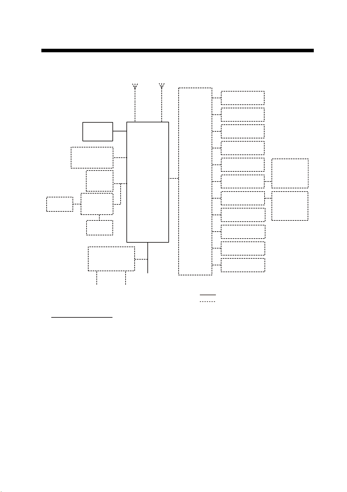
SYSTEM CONFIGURATION
PRINTER
PP-510
HANDSET
HS-2003
EXTERNAL
LOUDSPEAKER
SEM-21Q
PRINTER
PP-510/
PP-8800A
PRINTER
INTERFACE
IF-8500
OTHER
RADIO
TRX
ANT
TRANSCEIVER
FM-8900S
CH70
RX ANT
UNIT
JUNCTION
BOX
IF-8900
NAV
EQUIPMENT
VDR
ALARM
SYSTEM
ALARM UNIT
IC-350
INS/AIS/
PLOTTER
MIC RECEPTACLE
BOX RBD-VHF (B)
MIC RECEPTACLE
BOX RBD-VHF (B)
REMOTE STATION
RB-8900/RB-8900-W
REMOTE STATION
RB-8900/RB-8900-W
ANALOG WING
HANDSET
HS-6000FZ5/
HS-6000FZ11
ANALOG WING
HANDSET
HS-6000FZ5/
HS-6000FZ11
AC/DC POWER
SUPPLY UNIT
PR-240
24 VDC
100-115/200-230 VAC
1ø, 50/60 Hz
Environmental category
Antenna units: Exposed to the weather
All other units: Protected from the weather
24 VDC
Battery
REMOTE STATION
RB-8900/RB-8900-W
REMOTE STATION
RB-8900/RB-8900-W
: STANDARD
: OPTIONAL or LOCAL SUPPLY
xi

SYSTEM CONFIGURATION
This page is intentionally left blank.
xii
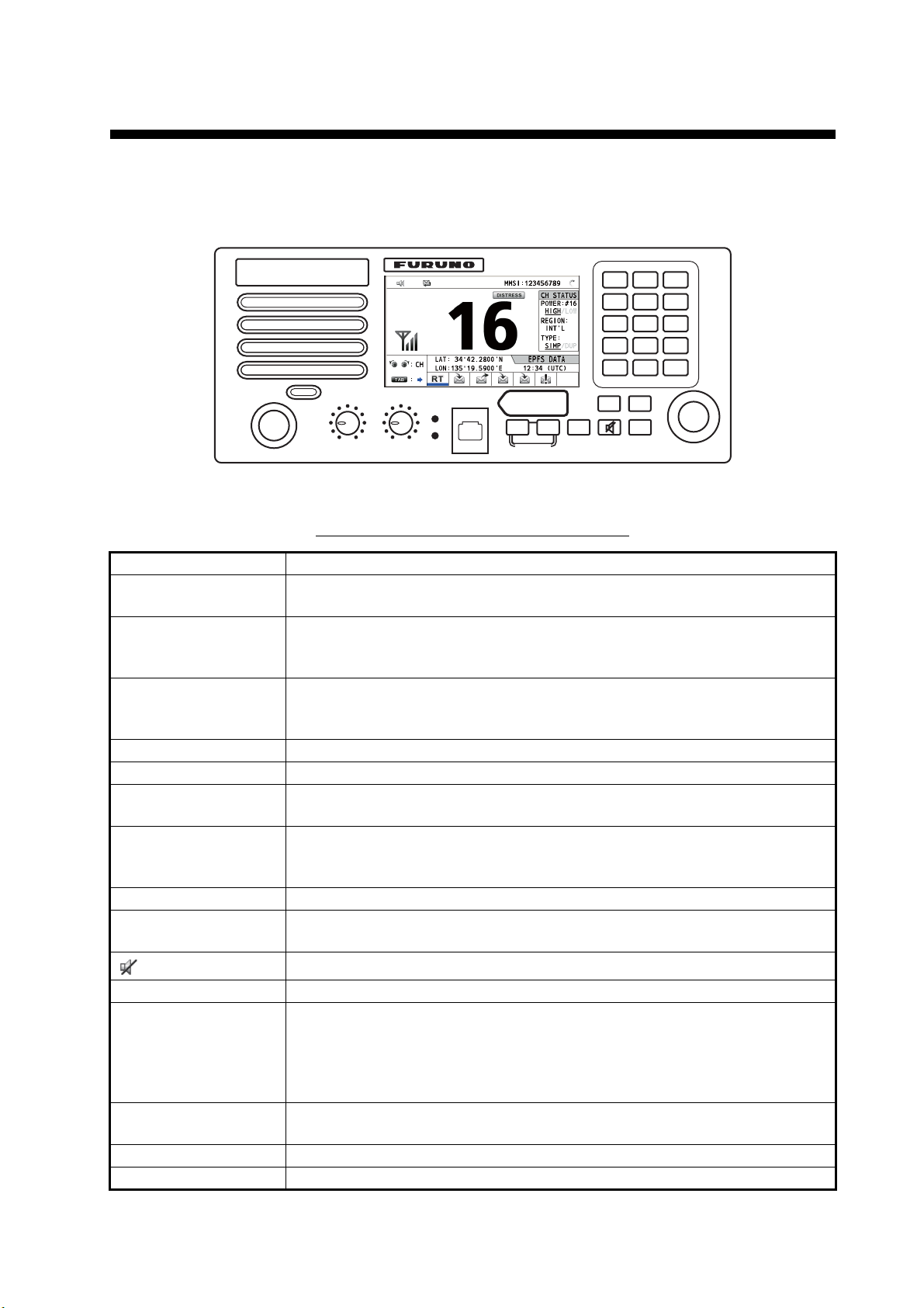
1. OPERATIONAL OVERVIEW
1.1 Controls
RT/
HI/LO
CH16
23
REPLAY
0
MENU
CANCEL
9758
CHANNEL
PUSH TO ENTER
HANDSET
REGION
1
46
DW/
SCAN
PWR OFF
VOLUME
SQUELCH
ALARM
AUTO
DISTRESS
Keep pressed for 4 sec in case
of DISTRESS. The alert is
transmitted with steady lighting.
DISTRESS
OTHER
MSG
DSC MSG
COMPOSE
DROBOSE MSG
TAB
BRILL
Transceiver unit
Description of controls for transceiver unit
Control Function
VOLUME/PWR knob • Turns the power on or off.
• Adjusts the volume.
CHANNEL/ENTER
knob
• Rotate to select channel.
• Rotate to select menu items or change the page in multi-page screens
(e.g., log data); push to confirm a selection.
SQUELCH knob Rotate to adjust the squelch. The squelch mutes the audio output in the ab-
sence of an incoming signal. AUTO position automatically reduces white
noise.
DISTRESS key Press and hold down the key four seconds to transmit the distress alert.
DISTRESS MSG key Composes DSC TX message for DISTRESS ALERT.
OTHER DSC MSG
key
Composes DSC TX message except DISTRESS ALERT and DROBOSE
(Distress Relay On Behalf Of Someone Else).
DROBOSE MSG key Composes DSC TX message for DROBOSE (Distress Relay On Behalf Of
Someone Else). Press the DISTRESS MSG key and the OTHER DSC
MSG key simultaneously.
BRILL key Adjusts the brilliance.
TAB key • Switches control to the tab area.
• Switches the session.
key
Turns the main speaker on or off.
MENU key Opens/closes the menu.
CANCEL key • Cancels the creation of the DSC message currently being created.
• Silences the audio alarm.
• Erases error message and pop-up message.
• Returns previous layer in multi-layer menu.
• Erases character input.
RT/REGION key • Switches to the RT (radiotelephone) screen.
• Opens/closes the option window for channel region.
HI/LO key Changes the output power to high (25 W) or low (1 W).
CH16 key Switches to the RT (radiotelephone) screen and sets CH16.
1-1

1. OPERATIONAL OVERVIEW
Control Function
0 to 9 keys • Enter alphabet, numeric or symbol.
• Direct selection of corresponding function on menu and applicable
screens.
DW/SCAN key
REPLAY key
ALARM lamps Top: Flashes in red when receiving distress alert, distress and urgency
• Opens the option window for DW or SCAN.
• Cancels DW or SCAN in process.
Opens the replay screen.
messages.
Bottom: Flashes in green when receiving safety and routine messages, and
when daily test is completed.
The flashing of a lamp for receiving a DSC message is in synch with the audio alarm.
The flashing cycle for both top and bottom lamps is 200 msec (lighting) →
200 msec (off) → 200 msec (lighting) → 200 msec (off) → …
1.2 How to Turn On/Off the Power
Rotate the VOLUME/PWR knob clockwise to turn on the power. The RT screen appears.
To turn off the power, rotate the VOLUME/PWR knob counterclockwise to the OFF position.
1.3 Radiotelephone (RT) Screen
Turn the power on, or press the RT/REGION key to show the radiotelephone (RT)
screen. This is where you set up the transceiver unit, and communicate by voice.
1
2
7
3
11
12
13
Radiotelephone (RT) screen on the transceiver unit
No. Meaning
1
Loudspeaker on ( ) or off ( )
2 This icon appears when the channel is busy.
3 Intensity of reception (This icon does not appear while transmitting.)
4 Own ship’s MMSI (nine digits)
5 Spinner rotates when the equipment is functioning normally.
6 This icon appears when the frequency is for distress.
7 Channel
8 Output power ([HIGH], [LOW])
9 Channel region ([INT’L], [USA], [CANADA], [INLAND-W], [PRIVATE])
4
6
8
9
10
15
5
14
Tab area: Sessions
in progress
1-2
1. OPERATIONAL OVERVIEW
No. Meaning
10 Channel type ([SIMP]: Simplex, [DUP]: Duplex)
11 Guidance: Rotate the CHANNEL/ENTER knob to select channel.
12 Guidance: Press the TAB key to switch the session.
13 Own ship’s position (LAT: Latitude, LON: Longitude)
Method of data input
[EPFS DATA]: The position and time data from EPFS.
[EPFS (OFFLINE)]: Indicates no position data from EPFS for ten minutes.
14
[EPFS (OLD)]: Indicates no position data from EPFS for four hours.
[MANUAL INPUT]: Set the position and time data manually.
[NO INFO]: No position and time data.
15 Time (UTC: universal time coordinated) of the position fix
1.4 How to Adjust the Brilliance of the Display and Panel
You can adjust the brilliance of the display and the panel for transceiver unit.
1. Press the BRILL key to show the [BRILL LEVEL
SETUP] window.
If necessary, press the 1 key to switch the [DAY/
NIGHT] mode.
Note: When switching the [DAY/NIGHT] mode
with the 1 key, the [BRILL LEVEL SETUP] window closes. Press the BRILL key again to show the window.
2. To adjust the [DISPLAY] brilliance, rotate the CHANNEL/ENTER knob or press
the BRILL key. (Default setting: 17 for [DAY], 7 for [NIGHT])
3. To adjust the [PANEL] brilliance, press the 4 (decrease the setting) or 6 (increase
the setting) key. (Default setting: 17 for [DAY], 12 for [NIGHT])
4. Push the CHANNEL/ENTER knob to save the settings and close the window. To
cancel the settings, press the CANCEL key instead of the CHANNEL/ENTER
knob to close the window.
Note 1: The equipment keeps values for [DAY] and [NIGHT] separately.
Note 2: The window closes automatically when there is no operation for four seconds.
Note 3: When you turn on the power with the display brilliance set to 0, the setting au-
tomatically changes to 1.
1.5 How to Select the Channel Region, Channel
Channel region
You can select the channel region by the RT/REGION key or the [REGION] menu.
By the
1. Press the RT/REGION key to open the [REGION] option on the RT
2. Rotate the CHANNEL/ENTER knob to select the channel region de-
RT/REGION key
screen.
sired then push the knob.
1-3
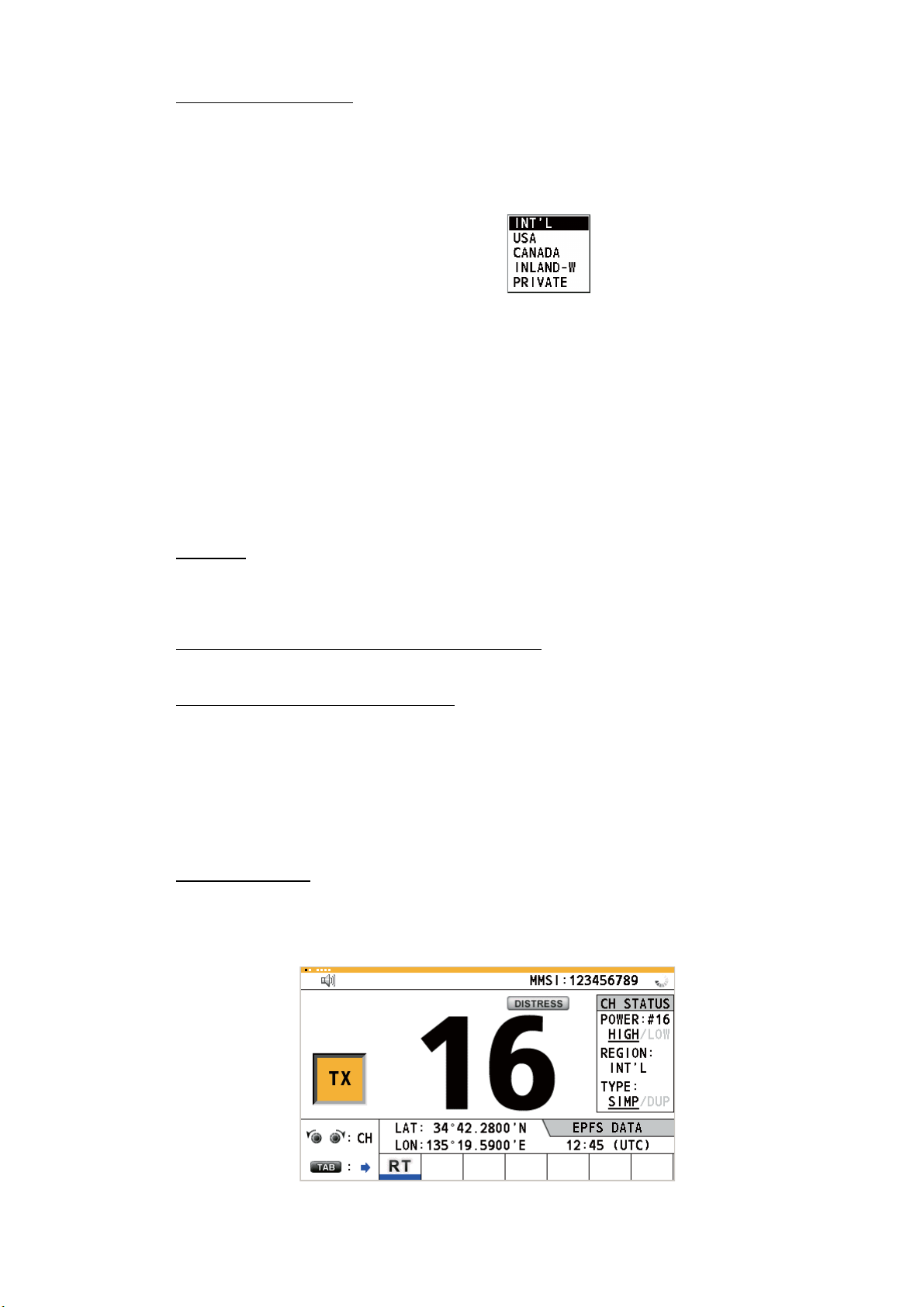
1. OPERATIONAL OVERVIEW
By the [REGION] menu
See paragraph 5.3.1.
1. Press the MENU key to open the [MENU] screen.
2. Rotate the CHANNEL/ENTER knob to select [CH MODE] then push the knob.
3. Rotate the CHANNEL/ENTER knob
to select [REGION] then push the
knob.
4. Rotate the CHANNEL/ENTER knob to select the channel region desired then
push the knob.
The following options are available.
• [INT’L]: International mode
• [CANADA]
• [PRIVATE]: Private channel mode
Note: Private channels are available only where permitted by the authorities. The
[USA], [CANADA], [INLAND-W], [PRIVATE] can also be set by a qualified service
technician.
: CANADA mode
• [USA]: USA mode
• [INLAND-W]: Inland waterway mode
Only permitted channel
regions are displayed,
which are set by the
installer of the equipment.
Channel
The channel can be set manually on the RT screen. Enter the channel by one of the
methods below.
Enter channel with the
Rotate the CHANNEL/ENTER knob on the RT screen.
CHANNEL/ENTER knob:
Enter channel with the numeric keys:
Use the numeric keys to enter channel on the RT screen then push the CHANNEL/
ENTER knob. The setting is automatically confirmed two seconds after entering, without pushing the CHANNEL/ENTER knob.
1.6 Transmission
How to transmit
Press the PTT (push-to-talk) switch on the handset with off hook to talk, and release
it to listen for a response. "TX" appears on the screen during transmission.
1-4
1. OPERATIONAL OVERVIEW
How to change the output power
Press the HI/LO key to change the output power between high and low alternately.
[HIGH] or [LOW] with underline appears in the [CH STATUS] area on the RT screen
depending on your selection.
1.7 How to Turn On/Off the Loudspeaker
You can turn the loudspeaker (other than DSC communication, error, and key beep)
on or off.
1. Press the key to alternately disable or enable the loudspeaker.
Speaker ON
2. To adjust the volume of the loudspeaker, rotate the VOLUME/PWR knob (cw: volume up, ccw: volume down).
Speaker OFF
1.8 Quick Selection of CH16
Press the CH16 key to select CH16. The CH16 (156.8 MHz) is the international frequency for distress traffic and for calling by radiotelephone. The CH16 can also be
used by ship stations for call and reply. To facilitate the reception of distress calls and
distress traffic, all transmissions on CH16 should be kept to a minimum and should not
exceed one minute. Before transmitting on the CH16, a station should listen on this
frequency for a reasonable period to make sure that no distress traffic is being sent.
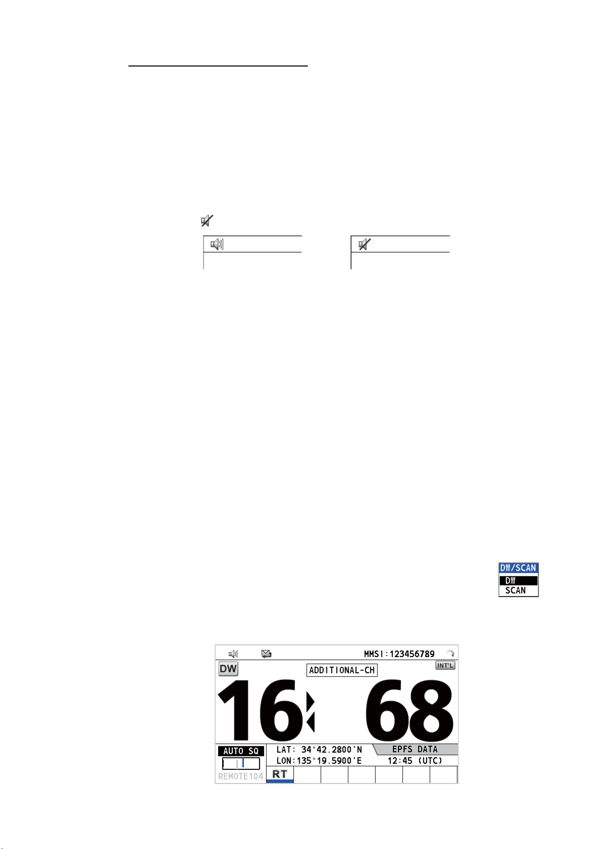
1.9 How to Scan Dual Channels (DW)
The DW function permits watch on CH16 and an operator-selected channel. CH16
and another channel are watched at intervals of 0.15 seconds and one second, respectively.
1. Select the other channel to watch then press the DW/SCAN key to
show the [DW/SCAN] option.
2. With [DW] selected, push the CHANNEL/ENTER knob. The following screen appears (channel 68 is selected in the example).
1-5

1. OPERATIONAL OVERVIEW
When the receiver detects a carrier and the squelch opens, the following occurs.
• When the squelch opens on the additional channel,
scanning dual channels.
• When the squelch opens on the CH16,
When the squelch closes, the scanning on dual channels restarts.
To stop the scanning on dual channels, do one of the following:
• Press the CANCEL key.
• Press the CH16 key.
• Press the DISTRESS key.
• Press the DW/SCAN key.
• Off hook a handset if there is one on hook.
• Press the PTT switch of a handset that is off hook. In this case, press the PTT switch
again to transmit.
• Activate another session.
• Select [HOLD] in the RT session.
• Select [QUIT] in the RT session.
• Press the MENU key.
• Press the RT/REGION key.
the CH16 is set.
the receiver continues
1.10 How to Scan All Channels
The receiver scans all channels at intervals of 0.15 seconds in the selected channel
mode in ascending channel order, watching CH16 between channels as below:
01 16 02 16 03 16 04...
16 88 16 87 16 86 16...
Note: TX is disabled when scanning.
1. Press the DW/SCAN key to show the [DW/SCAN] option.
2. With [SCAN] selected, push the CHANNEL/ENTER knob. The scanning starts
and the "SCAN" icon appears on the screen.
1-6

1. OPERATIONAL OVERVIEW
When the receiver detects a carrier and the squelch opens, the scanning is
stopped on that channel.
• When the squelch opens on the channel except CH16,
and CH16.
• When the squelch opens on the CH16,
When the squelch closes, the scanning restarts.
To stop the scanning, do one of the following:
• Press the CANCEL key.
• Press the CH16 key.
• Press the DISTRESS key.
• Press the DW/SCAN key.
• Off hook a handset if there is one on hook.
• Press the PTT switch of a handset that is off hook. In this case, press the PTT switch
again to transmit.
• Activate another session.
• Select [HOLD] in the RT session.
• Select [QUIT] in the RT session.
• Press the MENU key.
• Press the RT/REGION key.
the CH16 is set.
dual watch starts on it
1.11 How to Set the Auto Acknowledgement
Individual, PSTN (public switched telephone network), position, polling and test calls
can be acknowledged automatically or manually. This is set on the [ACK SETTINGS]
in the [DSC] menu (see section 5.16).
Note: When own ship's communication is high priority, set to manual acknowledgement.
The auto acknowledgement is not sent in the following cases:
• Other session is active.
• There are RT or DSC sessions (for individual call).
• Channel is in use.
• ECC is NG (No Good).
Note: The auto acknowledgement for the individual call is sent only when the proposed channel or communication mode is not available.
1.12 Priority of the System
If one or more remote stations are installed, the transceiver unit has the highest priority. You can interrupt remote station operation at any time with the handset of the main
unit. When you hook off the handset of the main unit, "OCCUPIED BY: FM-8900S"
(Default. This can be changed.) is indicated on all remote stations. Each remote station has its own priority. The remote station ID (1-4) indicates its priority. The priority
1-7
1. OPERATIONAL OVERVIEW
of the system is as follows.
Transceiver unit = Analog wing handset >
Digital wing handset L = Digital wing handset R > Remote station 1 >
Remote station 2 > Remote station 3 > Remote station 4
If you hook off No.4 remote station, for example, "IN USE BY: HANDSET_P4" is displayed on other remote stations and "HANDSET_P4: OPERATION" on the transceiver unit. However, you can hook off and use No.1 remote station.
The terminal which you operate has priority in the following conditions:
• The handset goes off hook.
• Display the menus or setting windows.
• Display each function screen (for example, Log).
• Switch the session.
• Press a key or rotate the CHANNEL/ENTER knob. (The priority is lost after four seconds.)
How to set the terminal ID
1. Disconnect the power plug of a remote station to turn off the remote station.
2. While pressing the MENU key of a remote station, connect the plug to turn on the
power.
3. Enter the terminal ID, using the 1 to 6 keys, then press the ENTER key. Do not
assign the same number to multiple remote stations.
4. Turn off and on the power of the transceiver unit.
1.13 Intercom
The built-in intercom permits voice communications between two terminals.
Calling
You can call over the intercom in on or off hook condition.
1. Press the MENU key to open the [MENU] screen.
1-8
2. Rotate the CHANNEL/ENTER knob to select [INTERCOM]
then push the knob.
3. Rotate the CHANNEL/ENTER knob to select
the called party’s terminal then push the knob.
The called party’s terminal rings.
To cancel calling, press the CANCEL key.
1. OPERATIONAL OVERVIEW
4. When the called party picks up their handset, the following screen appears.
Start communications.
Note: You do not have to press the PTT switch to communicate.
5. If needed, adjust the handset volume by rotating the CHANNEL/ENTER knob.
6. Hang up the handset or press the CANCEL key to turn the intercom off. The lastused screen appears.
Answering
1. The terminal rings and the following screen appears. To cancel reply, press the
CANCEL key.
2. Pick up the handset to start communications.
3. Hang up the handset or press the CANCEL key to turn the intercom off. The lastused screen appears.
1.14 Operation of Session
Description of session
There are two types of sessions: RT session and DSC session. When a session starts,
the applicable icon for the session appears in the tab area.
RT session
DSC sessions
Tab area
1-9
1. OPERATIONAL OVERVIEW
How to finish a single session
RT session
1. Press the TAB key to select the RT icon in the tab area.
2. Rotate the CHANNEL/ENTER knob to select [QUIT] then push the knob.
Step 2: Rotate the
CHANNEL/ENTER
knob to select [QUIT]
then push the knob.
DSC session
The cursor is in the tab area when the DSC session starts. Rotate the CHANNEL/ENTER knob to select [QUIT] then push the knob.
Step 1: Press the
TAB key to select
the RT icon.
Rotate the CHANNEL/ENTER
knob to select [QUIT] then
push the knob.
ACCEPT UNABLE PROPOSE
How to start a new session
When another session is active:
• When sending the distress alert
, all sessions except the distress alert TX session
automatically close then the distress alert TX session starts.
• When doing an RT session or sending a non-distress DSC message
, the currently
active session is put on hold then the RT session or non-distress DSC message TX
session starts.
• When receiving a DSC message
, its session is put on hold.
When no other session is active:
• When sending the distress alert
, all sessions except the distress alert TX session
automatically close then the distress alert TX session starts.
• When sending a non-distress DSC message
, its session becomes the active ses-
sion.
1-10
How to switch sessions
When one session is active and another message arrives, a new session for the received message does not start automatically. Only one session can be active. For ex-
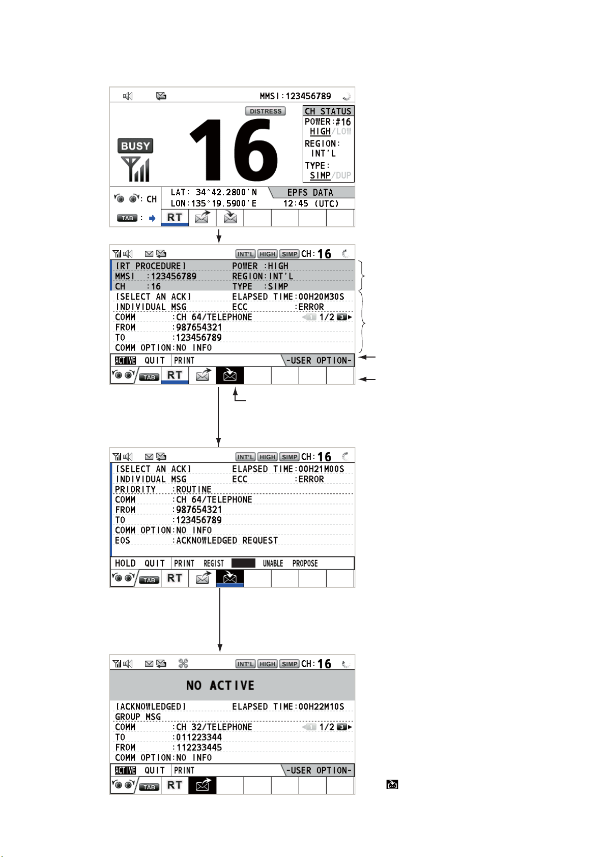
1. OPERATIONAL OVERVIEW
ample, when you are transmitting a DSC message and another message arrives, the
indication [ACTIVE] appears to indicate the start of a new session.
Press the TAB key to move the cursor to the tab area.
Information for the session
underlined in blue (RT in
this case)
Information for the session
selected by cursor.
User options area
Tab area
To select a session, press the TAB key. The cursor is here.
With [ACTIVE] selected, push the CHANNEL/ENTER knob to
switch the active session. To switch the option for the session
([ACTIVE], [QUIT], [PRINT]), rotate the CHANNEL/ENTER knob.
Only the screen for the selected
session appears.
ACCEPT
To finish this session, rotate the CHANNEL/ENTER knob to select
[QUIT] then push the knob.
Note: When waiting for the ACK, that is, the session is in progress,
the confirmation message appears. Rotate the CHANNEL/ENTER
knob to select [Yes] or [No] then push the knob.
The icon disappears.
1-11
1. OPERATIONAL OVERVIEW
How to close a session
To manually close a session, select it with the TAB key. Rotate the CHANNEL/ENTER knob to select [QUIT] in the user options area then push the knob. The session
icon disappears from the tab area.
When there is no operation for the time specified (see section 5.8), the inactive session is automatically closed.
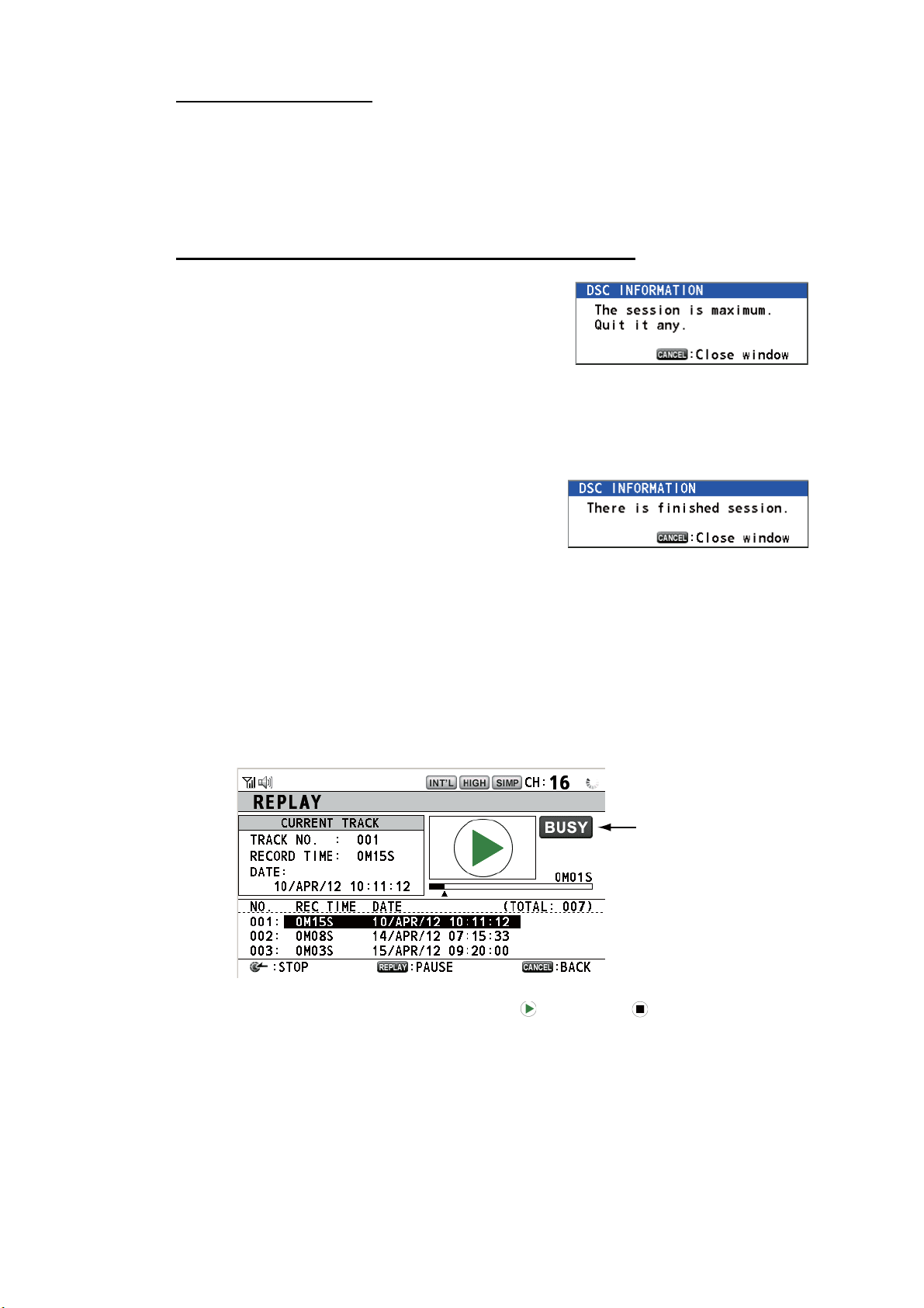
Processing when the number of sessions is maximum
A maximum of seven sessions can be displayed in
the tab area. If a seventh session starts, the message as shown in the right figure appears on the
screen. Press the CANCEL key to close the message. Close a session to make space for the new
session.
If the eighth session is for sending a distress alert, all sessions except that session
automatically close, and the session starts.
If the eighth session is for receiving DSC message,
the lowest-priority session automatically closes
and the message as shown in the right figure appears. Press the CANCEL key to close the message.
1.15 Replay Function
You can replay a recorded voice, which has been received recently, for a total of 120
seconds. The recorded voices are saved in this equipment with the channel information, and deleted when turning the power off.
To replay the recorded voice, press the REPLAY key.
When the replaying is finished, the indication changes to .
To change the track number, rotate the CHANNEL/ENTER knob to select the track
number desired then push the knob to replay the selected data.
Appears only when
the squelch opens.
1-12
To stop the replaying and close the screen in the middle, press the CANCEL key. Also, you can stop the replaying with the CHANNEL/ENTER knob. In this case, the [REPLAY] screen does not close.
Note: When the time limit (120 seconds) has passed, the recorded data is deleted per
track in earliest to latest order.

2. DSC OVERVIEW
2.1 What is DSC?
DSC is an acronym meaning Digital Selective Calling. It is a digital distress and general calling system in the VHF band used by ships for transmitting distress alerts and
general calls and by coast stations for transmitting the associated acknowledgements.
For DSC distress, safety and urgency callings in the VHF band, the channel is 70.
Distress, Safety, Urgency and Routine DSC Calls
Distress, Safety, Urgency and Routine DSC Calls
CH70 RX ANT
TRANSCEIVER
UNIT
ANT
2.2 DSC Messages
DSC calls are roughly divided in two groups: distress messages and general (safety,
urgency and routine) messages. Below are the types of DSC messages.
Call Description
DISTRESS ALERT Your ship sends distress message.
DISTRESS RELAY
ALL
DISTRESS RELAY
INDIVIDUAL
MEDICAL MSG* Inform areas that your ship is carrying medical supplies.
NEUTRAL MSG* Inform areas that your ship is not a participant in armed conflict.
INDIVIDUAL MSG Call to a specific address.
PSTN MSG Call over Public Switched Telephone Network (PSTN).
TEST MSG Send test signal to a station to test your station's functionality.
GROUP MSG Call to a specific group.
ALL SHIPS MSG Call to all ships.
POSITION MSG Your ship requests position of other ships.
POLLING MSG Confirm if your ship is within communicating range with other ships. (Re-
*SPECIAL MSG: To send these messages, set [SPECIAL MSG] to [ABLE]. See
section 5.17.
Your ship relays distress call to all ships.
Your ship relays distress call to a coast station or all ships.
ceive and answer only)
2-1
2. DSC OVERVIEW
Contents of a DSC call
• Calling category
DISTRESS
DIVIDUAL, DISTRESS RELAY AREA (Received only), DISTRESS ACK
GENERAL
TEST MSG, GROUP MSG, ALL SHIPS MSG, POSITION MSG, POLLING MSG
• Station ID (MMSI)
Your ship ID and sending station ID. Coast station ID begins with 00; Group ID begins with 0.
• Priority
Distress
Urgency
ship, aircraft or other vehicle or safety of person.
Safety
meteorological warning.
Routine
• Communication mode
TELEPHONE
: DISTRESS ALERT, DISTRESS RELAY ALL, DISTRESS RELAY IN-
: MEDICAL MSG, NEUTRAL MSG, INDIVIDUAL MSG, PSTN MSG,
: Grave and imminent danger and request immediate assistance.
: A calling station has a very urgent call to transmit concerning safety of
: A station is about to transmit a call containing an important navigational or
: General calling
: Telephone (F3E/G3E) by VHF radiotelephone
• Communication channel
Working frequency channel used to call by telephone. The sending station may
have the receiving station (ship or coast station) assign the frequency channel to
use.
• Position
Position can be automatically or manually set.
• End code
The end of a DSC call is indicated with "EOS" (acknowledgement, acknowledgement required, no acknowledgement required).
2.3 Audio Alarms
When you receive a distress alert or general call addressed to your ship, the audio and
visual alarms are released. The audio alarm can be silenced with the CANCEL key.
Alarm When Frequency (interval)
Count
alarm
Distress
RX alarm
Distress
TX alarm
Distress
ACK
alarm
Urgency
alarm
Urgency
ACK
alarm
Counting down the time remaining before the distress
alert is transmitted.
The following sessions are received:
distress alert, relay individual, relay area, or relay all.
Sending or resending the distress alert. 2200 Hz (2000 ms); once
The following sessions are received or received then acknowledged:
distress ACK, distress ACK (cancel ACK), relay individual ACK, or relay all ACK.
The following urgency sessions are received:
all ships, neutral, medical, or individual.
The sessions for urgency individual ACK are received
then acknowledged. The sessions for delayed ACK are
received.
2000 Hz (500 ms) → silent
(500 ms); three times
2200 Hz (250 ms) → 1300 Hz
(250 ms); repetition
2200 Hz (500 ms) → 1300 Hz
(500 ms); repetition
2200 Hz (250 ms) → silent
(250 ms); repetition
2200 Hz (500 ms) → silent
(500 ms); repetition
2-2
2. DSC OVERVIEW
Alarm When Frequency (interval)
Ordinary
alarm
The following sessions are received:
• Safety: all ships, individual, position, or test.
• Routine: individual, group, polling, or PSTN.
The following set is repeated:
750 Hz (50 ms) and 650 Hz
(50 ms); ten times → silent
(2000 ms); once
Ordinary
ACK
alarm
Self terminating
alarm
The following sessions are received then acknowledged:
• Safety: individual ACK, position ACK, test ACK.
• Routine: individual ACK.
The sessions for delayed ACK are received.
• There are the related sessions for call messages.
• The related sessions for ACK messages were already
acknowledged.
• Sending the individual unable auto ACK or PSTN un-
The following set is repeated:
750 Hz (50 ms) and 650 Hz
(50 ms); ten times → silent
(2000 ms); once
1300 Hz (100 ms) → silent
(300 ms) → 1300 Hz (100 ms)
→ silent (50 ms) → 1300 Hz
(100 ms)
able auto ACK.
• The following sessions are received:
relay area (duplicate), relay all (duplicate), or PSTN
end of call ACK.
2.4 Description of Call Screens
This section provides the information necessary for interpreting the receive and send
call screens.
2.4.1 RX calls
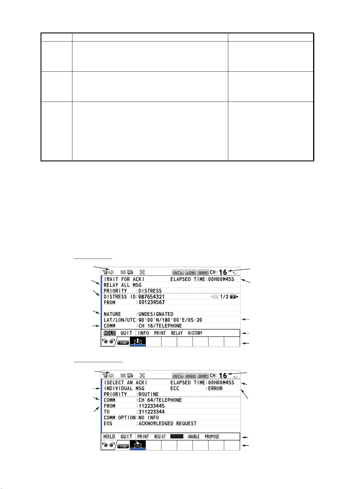
Below are sample distress relay and individual RX call screens. The contents of other
types of RX calls are similar to that of the individual call.
Distress relay
Speaker icon
Call type
ID No. (MMSI)
of ship in
distress
Nature of
distress
Communication
mode and
suggested
channel
Individual RX call
Working channel
to use
Elapsed time since
distress alert received
Position of ship
in distress
Available user options
Session in progress
Speaker icon
Call type
Communication
mode
ID No. (MMSI)
of ship
sending this
message
ACCEPT
Working channel
to use
Elapsed time since
call received
Appears when ECC
is NG.
Available user options
Session in progress
2-3
2. DSC OVERVIEW
The characters "*", "-" appear on the DSC receiving screen in the following conditions:
• "*" indicates a corrupt character in received data.
• "-" indicates missing digits after decimal point when receiving position data with no
info for expansion (expansion: digits after decimal point).
Examples:
1) When receiving position data without expansion, the indication is
"LAT: 12°34’N".
2) When receiving position data with expansion, the indication is
"LAT: 12°34,5678’N".
3) When receiving position data with no info for expansion, the indication is
"LAT: 12°34,----’N".
2.4.2 TX calls
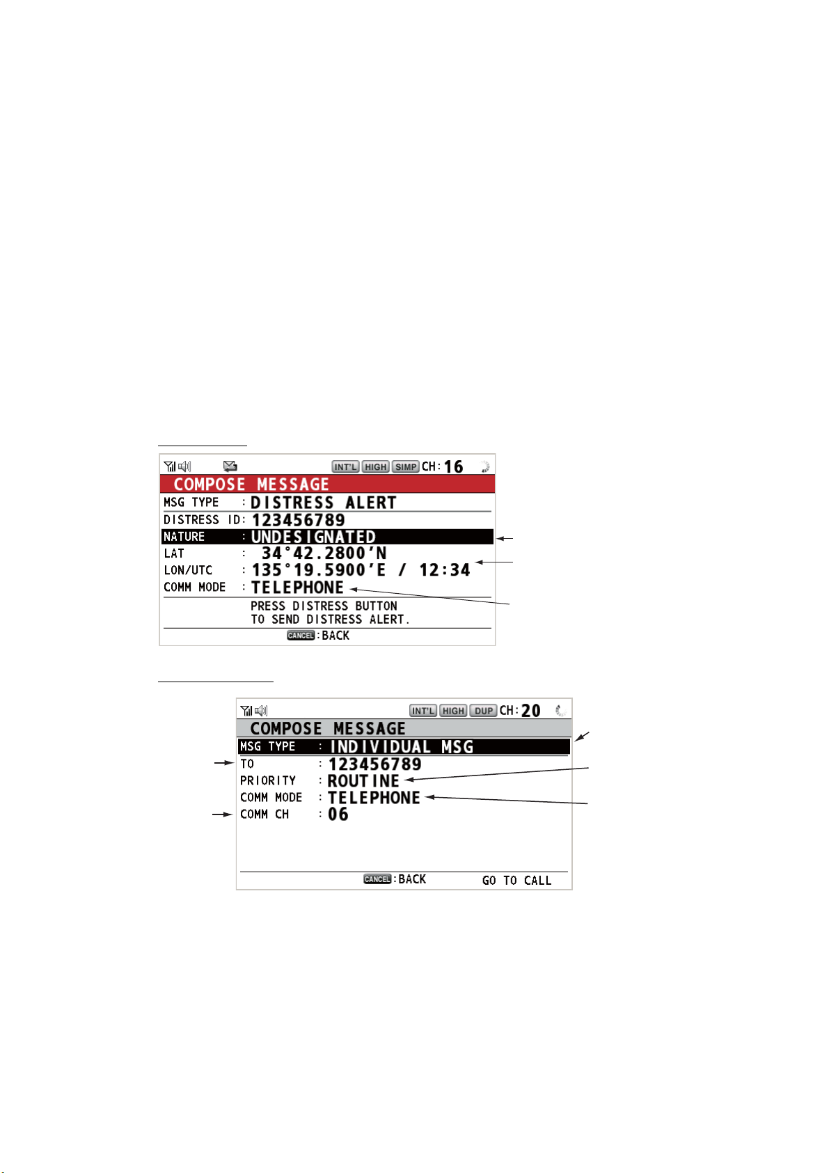
Below are sample distress alert and individual TX call screens. The contents of other
types of TX calls are similar to that of the individual call.
Distress alert
Individual TX call
ID No. of station
where message
is to be sent
Communication
channel
Nature of Distress
Position of ship in distress (your
ship) and time of distress position
Communication mode
Message type
(Individual)
Priority (Routine,
Safety, Urgency)
Communication
mode
2-4
Loading...