


 Loading...
C
9 - 5 2 , A s h i h a r a - c h o , N i s h i n o m i y a , J a p a n
T e l e p h o n e : |
0 7 9 8 - 6 5 - 2 1 1 1 |
T e l e f a x : |
0 7 9 8 - 6 5 - 4 2 0 0 |
A l l r i g h t s r e s e r v e d .  Printed in Japan
P U B . N o . I M E - 3 4 0 4 0 - J
( T E N I ) |
F A R / F R - 2 8 1 5 / 2 5 |
|
 Y o u r L o c a l A g e n t / D e a l e r
F I R S T E D I T I O N |
: |
A U G . |
1 9 9 5 |
J |
: |
N O V . |
0 5 , 2 0 0 1 |


TABLE OF CONTENTS
EQUIPMENT LISTS ............................................................................ |
iii |
1. MOUNTING
1.1 |
Scanner Unit .................................................................................................................... |
1-1 |
1.2 |
Mounting the Display Unit .............................................................................................. |
1-5 |
1.3 |
Mounting the Separate Type Control Panel ..................................................................... |
1-6 |
2. CONNECTIONS
2.1 |
Scanner Unit .................................................................................................................... |
2-1 |
2.2 |
Display Unit Connections ................................................................................................ |
2-6 |
2.3 |
Changing Power Specifications ..................................................................................... |
2-13 |
3. INITIALIZATION AND ADJUSTMENT
3.1 |
Menus for Initialization and Adjustment |
.........................................................................3-1 |
3.2 |
Heading Alignment .......................................................................................................... |
3-2 |
3.3 Adjusting Sweep Timing ................................................................................................. |
3-2 |
|
3.4 Adjusting Video Signal Level .......................................................................................... |
3-3 |
|
3.5 |
Suppressing Main Bang ................................................................................................... |
3-4 |
3.6 |
Confirming Tuning .......................................................................................................... |
3-4 |
3.7 |
Confirming Magnetron Heater Voltage ........................................................................... |
3-5 |
3.8 |
Initial Settings Menus ...................................................................................................... |
3-6 |
3.9 |
Setting the Function Keys ................................................................................................ |
3-8 |
3.10 Default of Initial Setting Menus .................................................................................. |
3-11 |
|
3.11 How to adjust ARP board ............................................................................................ |
3-12 |
|
3.12 Installation Check List ................................................................................................. |
3-14 |
|
4. INSTALLATION OF GYRO CONVERTER GC-8 (option)
4.1 |
General Procedure for Installing and Setting up the GYRO CONVERTER Board ........ |
4-1 |
4.2 |
Connection of External Power Supply ............................................................................ |
4-3 |
4.3 |
Confirming Gyrocompass Specifications ........................................................................ |
4-3 |
4.4 Changing Settings on the GYRO CONVERTER Board ................................................. |
4-4 |
|
4.5 |
Setting the Bearing on the Radar Display ........................................................................ |
4-8 |
i

SCHEMATIC DIAGRAMS AND OUTLINE DRAWINGS
SCHEMATIC DIAGRAMS |
|
Interconnection Diagram ............................................................................................... |
S-1 |
Display Unit General Schematic .................................................................................... |
S-2 |
Scanner Unit Schematic Diagram .................................................................................. |
S-3 |
INT-Board INT-9170 (1/2) ............................................................................................. |
S-4 |
INT-Board INT-9170 (2/2) ............................................................................................. |
S-5 |
OUTLINE DRAWINGS |
|
Display Unit (tabletop) .................................................................................................. |
D-1 |
Display Unit (tabletop type, separate control panel) ...................................................... |
D-2 |
Control Unit ................................................................................................................... |
D-3 |
Display Unit (console type) ........................................................................................... |
D-4 |
Radar Scanner Unit ........................................................................................................ |
D-5 |
Radar Scanner Unit ........................................................................................................ |
D-6 |
LIST OF INSTALLATION MATERIALS, ACCESSORIES AND SPARE PARTS ........... |
L-1 |
ii

EQUIPMENT LISTS
Complete set
No. |
Name |
Type |
Qty |
Remarks |
|
|
|
|
|
1 |
Scanner unit |
|
1 |
|
|
|
|
|
|
2 |
Display unit |
RDP-115 |
1 |
Pedestal mount type |
|
|
|
|
|
|
|
|
|
Tabletop type |
|
|
|
|
|
3 |
Accessories |
FP03-05710 |
1 set |
For built-in control unit, |
|
|
|
|
FP03-05701 |
|
|
|
|
FP03-05704 |
|
|
|
|
FP03-05705 |
|
|
|
|
03-133-184 |
|
|
|
|
|
|
|
FP03-05730 |
|
For separate control unit, |
|
|
|
|
FP03-05701 |
|
|
|
|
FP03-05703 |
|
|
|
|
FP03-05704 |
|
|
|
|
FP03-05705 |
|
|
|
|
03-133-1811 |
|
|
|
|
|
4 |
Installation materials |
CP03-19104 |
1 set |
For scanner unit |
|
|
|
|
|
|
|
CP03-14602 |
1 set |
For display unit |
|
|
|
|
|
5 |
Signal cable |
RW-4873 *15m* |
1 |
no armor |
|
|
|
|
|
|
|
RW-4873 *20m* |
|
|
|
|
|
|
|
|
|
RW-4873 *30m* |
|
|
|
|
|
|
|
|
|
RW-6895 *15m* |
|
w/armor |
|
|
|
|
|
|
|
RW-6895 *20m* |
|
|
|
|
|
|
|
|
|
RW-6895 *30m* |
|
|
|
|
|
|
|
|
|
RW-6895 *50m* |
|
|
|
|
|
|
|
6 |
Spare parts |
SP03-08902 |
1 set |
For scanner unit |
|
|
|
|
|
|
|
SP03-11301 |
1 set |
For display unit |
|
|
|
|
|
iii
Optional equipment
No. |
Name |
Type |
Code No. |
Remarks |
|
|
|
|
|
1 |
Hand grips |
OP03-70 |
008-423-420 |
For display unit |
|
|
|
|
|
2 |
M card fixing plate |
OP03-133 |
008-452-400 |
|
|
|
|
|
|
3 |
Hood |
FP03-0574 |
008-459-810 |
|
|
|
|
|
|
4 |
Display unit cover |
OP03-126 |
008-459-820 |
Tabletop w/built-in control unit |
|
|
|
|
|
|
|
OP03-127 |
008-459-760 |
Tabletop w/separate control unit |
|
|
|
|
|
|
|
OP03-128 |
008-459-890 |
Pedestal mount |
|
|
|
|
|
5 |
Display unit |
OP03-129-1 |
008-459-830 |
Converts from tabletop type/built-in |
|
conversion kit |
|
|
control unit to pedestal mount |
|
OP03-129-2 |
008-452-410 |
||
|
|
|
||
|
|
|
|
|
|
|
OP03-130-1 |
008-459-900 |
Converts from tabletop type/separate |
|
|
|
|
control unit to pedestal mount |
|
|
OP03-130-2 |
008-452-430 |
|
|
|
|
||
|
|
|
|
|
|
|
OP03-131 |
008-459-910 |
Converts from pedestal mount to tabletop |
|
|
|
|
type/built-in control unit |
|
|
|
|
|
|
|
OP03-132-1 |
008-459-920 |
Converts from pedestal mount to tabletop |
|
|
|
|
type/separate control unit |
|
|
OP03-132-2 |
008-452-450 |
|
|
|
|
||
|
|
|
|
|
6 |
Control panel |
OP03-134 |
008-461-340 |
For fastening separate type control unit to |
|
fixing plate |
|
|
a tabletop |
|
|
|
|
|
7 |
Video plotter/ |
RP-25 |
|
Mandatory for IMO radar |
|
Radar map |
|
|
|
|
|
|
|
|
8 |
Gyro converter |
GC-8-2 |
008-446-520 |
With installation materials |
|
|
|
|
|
9 |
Interswitch |
RJ-7 |
|
|
|
|
|
|
|
10 |
External buzzer |
OP03-21 |
000-030-097 |
1 m, with connector |
|
|
|
|
|
11 |
Performance |
PM-30 |
|
Mandatory for IMO radar |
|
monitor |
|
|
|
|
|
|
|
|
12 |
Range unit |
OP03-110-1 |
008-446-610 |
To km |
|
conversion kit |
|
|
|
|
|
|
|
|
13 |
Range unit |
OP03-110-2 |
008-452-200 |
To sm |
|
conversion kit |
|
|
|
|
|
|
|
|
14 |
Color display unit |
CD-141 |
|
|
|
|
|
|
|
15 |
Slave display unit |
FMD-8000 |
|
|
|
|
|
|
|
16 |
Transformer unit |
RU-1758 |
000-030-416 |
Converts 220 VAC to 100 VAC |
|
|
|
|
|
17 |
Transformer unit |
RU-1803 |
000-030-420 |
Converts 440 VAC to 100 VAC |
|
|
|
|
|
18 |
Interswitch |
RJ-8 |
|
|
|
|
|
|
|
19 |
Interface unit |
IF-2300 |
|
Mandatory for IMO radar |
|
|
|
|
|
iv
1. MOUNTING
1.1 Scanner Unit
Mounting considerations
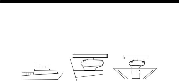
•The scanner unit is generally installed either on top of the wheelhouse or on the radar mast, on a suitable platform. Locate the scanner unit where there is a good all-round view.
(a) On bridge |
(b) Common mast |
(c) Radar mast |
Figure 1-1 Mounting methods
•No funnel, mast or derrick should be within the vertical beamwidth of the scanner in the bow direction, especially zero degrees ± 5° , to prevent blind sectors and false echoes on the radar picture.
•It is rarely possible to place the scanner unit where a completely clear view in all directions is available. Thus, you should determine the angular width and relative bearing of any shadow sectors for their influence on the radar at the first opportunity after fitting.
•Locate the antenna of a direction finder clear of the scanner unit to prevent interference to the direction finder. A separation of more than two meters is recommended.
•To lessen the chance of picking up electrical interference, avoid where possible routing the signal cable near other onboard electrical equipment. Also avoid running the cable in parallel with power cables.
•A magnetic compass will be affected if placed too close to the scanner unit. Observe the following compass safe distances to prevent deviation of a magnetic compass: Standard compass,1.70 m (FR-2815), 2.10 m (FR-2825), Steering compass, 1.90 m (FR-2815), 1.20 m (FR-2825).
•Do not paint the radiator aperture, to ensure proper emission of the radar waves.
•The signal cable run between the scanner and the display is available in lengths of 15 m (standard), 20 m, and 30 m. Whatever length is used it must be unbroken; namely, no splicing allowed.
•The scanner base is made of cast aluminum. To prevent electrolytic corrosion of the scanner base, use the seal washers and corrosion-proof rubber mat and ground the unit with the ground wire (supplied).
•Deposits and fumes from a funnel or other exhaust vent can adversely affect the aerial per-
formance and hot gases may distort the radiator portion. The scanner unit must not be mounted where the temperature is more than 70° C.
•Leave sufficient space around the unit for maintenance and servicing. See the scanner unit outline drawing for recommended maintenance space.
1 - 1
Assembling the scanner unit
The scanner unit consists of the scanner radiator and the scanner unit chassis, and they are packed separately. Fasten the scanner radiator to the scanner unit chassis as follows:
1)For the XN20AF, XN24AF, attach two guide pins to the underside of the scanner radiator.
2)Remove the waveguide cap from the radiator bracket. The cap may be discarded.
3)Coat the waveguide flange with anticorrosive sealant as shown in Figure 1-2.
10 mm O-ring
Hole for |
Hole for |
a guide pin |
a guide pin |
5 mm
Anticorrosive sealant
Figure 1-2 Coating the waveguide flange with anticorrosive sealant
4)Coat fixing holes for the scanner radiator with anticorrosive sealant.
5)Grease the O-ring and set it to the O-ring groove of the radiator flange.
6)Set the scanner radiator to the radiator bracket.
7)For the XN20AF, XN24AF, coat hex bolts (M8 x 40, slotted washer head, 8pcs.) with anticorrosive sealant and use them to loosely fasten the scanner radiator to the scanner unit chassis. For the XN12AF, coat hex bolts, flat washers and spring washers with anticorrosive sealant and use them to loosely fasten the scanner radiator to the scanner unit chassis.
8)Remove two guide pins (inserted at step 1), and then tighten fixing bolts.
 CAUTION
Be sure to remove the guide pins.
Injury may result if the guide pins loosen and fall.
1 - 2
Antenna radiator
Guide pin (XN20AF, XN24AF only)
Waveguide
Radiator bracket
|
Hex bolt (M8X40), 8 pcs. |
|
(XN20AF, XN24AF only) |
|
Hex bolt (M8X35), 8 pcs. |
|
Flat washer |
|
Spring washer |
O-ring |
(XN12AF only) |
Figure 1-3 Fastening the radiator to the radiator bracket
Fastening the scanner unit to the mounting platform
The scanner unit may be assembled before hoisting it to the mounting platform. However, do not lift the scanner unit by the radiator. Always hold the unit by its housing. When using a crane or hoist, lift the unit by the hoist rings which should be fastened to the bolt fixing covers of the scanner housing.
 CAUTION
DO NOT lift the antenna unit by the radiator; lift it by the hoist rings. (Be sure to remove rings after hoisting the antenna unit.)
Hoist |
|
NO! |
ring |
|
|
|
|
|
|
|
|
1)Construct a suitable mounting platform referring to the outline drawing at the back of the manual.
2)Drill four mounting holes of 15 mm diameter and one cable entry hole of about 50 mm diameter in the mounting platform.
3)Lay the rubber mat (supplied) on the mounting platform.
1 - 3

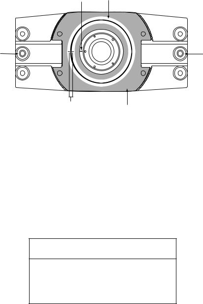
4)Place the scanner unit on the rubber mat orienting the unit so the bow mark on its base is facing the ship’s bow.
Ground terminal
Rubber mat
Bow mark
Figure 1-4 Scanner unit, front view
5)Fasten the scanner unit to the mounting platform with M12x60 hex bolts, nuts, flat washers and seal washers.
6)Using hex bolt (M6x25), nut (M6) and flat washer (M6) establish the ground system on the mounting platform as shown in Figure 1-5. The location should be within 370 mm of the ground terminal on the scanner unit. Connect the ground wire (RW-4747, 370 mm, supplied) between the grounding point and ground terminal on the scanner unit. Coat the entire ground system with silicone sealant (supplied).
|
|
|
Ground wire |
Hex bolt |
|
Anticorrosive sealant |
|
Spring washer |
|||
Seal washer |
|
||||
|
|
||||
Rubber mat |
|
|
|||
|
|
|
|
Spring washer |
|
|
|
|
Anticorrosive |
Hex nut |
|
Anticorrosive |
OR |
||||
sealant |
|||||
sealant |
Ground wire |
Hex nut |
|||
|
|
|
|||
|
|
|
|
||
|
|
|
|
Spring washer |
|
|
|
|
|
||
|
|
|
|
Flat washer |
|
|
|
|
|
Hex bolt welded to |
|
|
|
|
|
ship’s superstructure |
|
Anticorrosive sealant
Ground terminal
Ground wire
Antenna base
 CAUTION
Ground the equipment to prevent electrical shock and mutual interference.
Figure 1-5 Fastening the antenna unit to the mounting location
1 - 4

1.2 Mounting the Display Unit
The display unit is designed to be mounted on a tabletop or on a pedestal (option).
Before mounting the display unit
If Gyro Converter GC-8 (option) is to be used, install and setup the GYRO PROCESSOR Board before mounting the display unit, because of the difficulty involved if done after the unit is mounted. Instructions for installation and setup are in Chapter 4.
Siting considerations
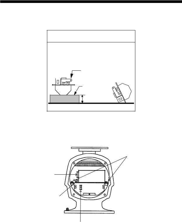
Locate the display unit on the bridge in a place where it can be viewed and operated conveniently. In addition, consider the points noted in the figure which follows.
CAUTION
A magnetic compass will be affected if placed too close to the display unit. The minimum compass safe distances for magnetic compasses are
standard compass:1.6 m steering compass: 1.2 m
Consider the points mentioned below when selecting a mounting location for the display unit.
•The orientation of the display unit should be so the operator views the screen while facing the bow. This makes determination of position much easier.
•The location should be free of water spray.
•The daylight bright type radar display
provides excellent visibility even in direct sunlight. However, locate the unit out of direct sunlight and away from heat sources because of heat that can build up inside the cabinet.
•The mounting location should be determined considering the length of the signal cable between the antenna unit and the display unit. (The signal cable comes in lengths of 15, 20 or 30 meters; maximum 100 meters.)
•Leave sufficient space around the unit for maintenance and servicing. See the display unit outline drawing for recommended maintenance space.
1 - 5
Mounting procedure
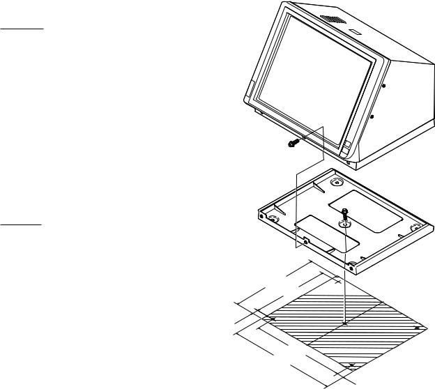
Tabletop
1)Unfasten the three M10 bolts at the front of the display unit and separate the mounting base from the display unit.
2) Drill five holes of 12mm diameter in the tabletop.
3)Secure the mounting base to the tabletop by using M10 nuts, bolts and flat washers.
4)Place the display unit on the mounting base and fasten it to the mounting base with the bolts removed in step 1.
Pedestal
Fix the pedestal to the mounting location with M12 nuts, bolts and washers. (The cable gland is at the bottom of the pedestal.) See the outline drawing at the back of this manual.
70
1.3Mounting the Separate Type Control Panel
529.5  460
460 
560  644
644 
The separate type control panel connects to the display unit with a connection cable. Nonslip rubber feet (supplied) can be attached to the bottom of the control panel. The panel can be permanently fixed to a tabletop with the control panel fixing plate kit (option).
42
Figure 1-6 Mounting dimensions for tabletop mount display unit
1 - 6
2. CONNECTIONS
2.1 Scanner Unit
 CAUTION
The magnetron in the transceiver module will demagnetize if it contacts ferrous material. When dismounting the transceiver module, lay it on its side or on top of non-ferrous material as shown below.
Transceiver module |
(magnetron inside) |
Non-ferrous |
block |
Height more than 5 cm
1)Open the scanner unit cover.
2)Disconnect plugs P611, P801 and P821.
3)Unfasten the transceiver module (two bolts). Remove the transceiver module.
Fixing bolts
J611
J801
J821
Figure 2-1 Scanner unit, front view
2 - 1
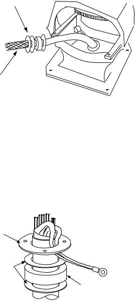
4)Unfasten the four fixing bolts on the cable gland at the base of the scanner unit. Remove clamping ring, rubber gasket and washers.
From left: Clamping ring, washer, rubber gasket and washer
Signal cable
Figure 2-2 Scanner unit, front view, cover removed
5)Pass the signal cable through the cable entry hole in the scanner unit mounting platform. Trim the cable so about 80 cm of it protrudes past the cable gland.
6)Slide the clamping ring, washer, rubber gasket and washer onto the cable in that order.
7)Fabricate the signal cable as shown on page 2-4 (signal cable RW-4873), or page 2-5 (signal cable RW-6875).
8)Referring to Figure 2-3, pass the outer and inner shields between the signal cable and the clamping ring. Fasten the cable gland.
Clamping
ring
Washers
Rubber gasket
Figure 2-3 Passing cable shields between cable and clamping ring
9)Connect the signal cable to the terminal board RTB801 by referring to the interconnection diagram. Leave “slack” in the coaxial wire to prevent breakage.
10)Bind cores of cables with cable ties.
11)Mount the transceiver module. Connect plugs P611, P801 and P821. Fasten the shield to the ground terminal on the transceiver module.
2 - 2
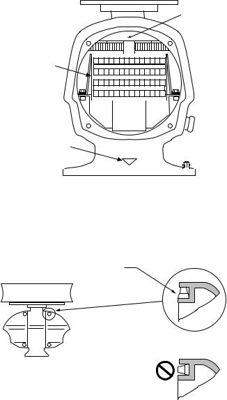
12)If the scanner is mounted 2° or more left of ship’s bow, adjust the position of S901 so it becomes “on” (contact between #1 and #2 on pcb MP-3795). To access S901, open the bow side cover; S901 is above the drive gear.
S901
RTB801
Bow mark
1 |
2 |
3 |
4 |
5 |
6 |
7 |
8 |
9 |
10 11 12 13 14 |
15 16 17 18 19 |
20 21 22 23 24 25 26 27 28 |
||||||||
Figure 2-4 Scanner unit, front view
13)Confirm that all screws are tightened and all wiring is properly made. Coat waterproofing gasket, bolts and tapping holes of scanner unit with silicone grease. Check that the waterproofing gasket is seated as shown in Figure 2-5. Close the scanner unit cover.
Coat gasket with silicone grease.
DO NOT use silicone sealant.
CORRECT
WRONG
Figure 2-5 Correct seating of waterproofing gasket
2 - 3

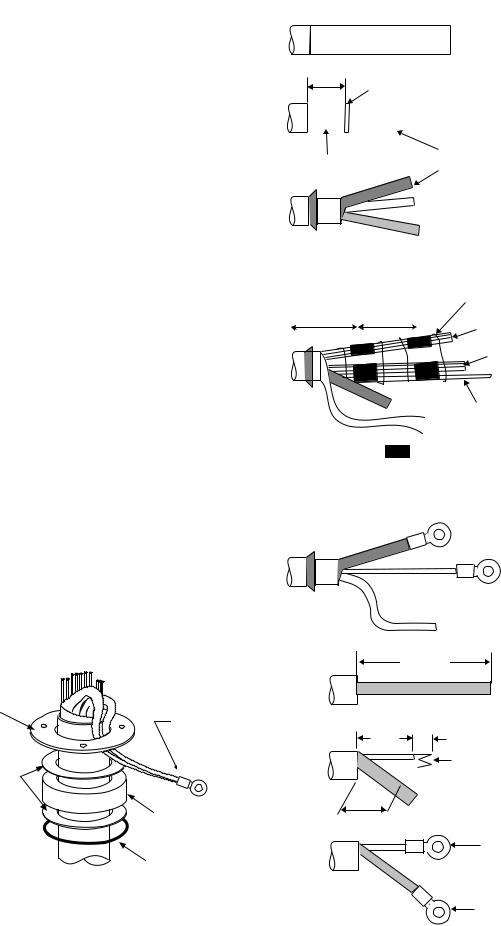
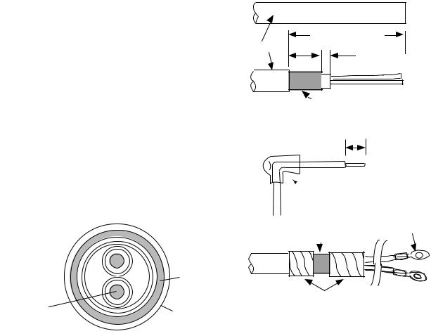
Fabricating signal cable RW-4873
1)Remove the vinyl sheath by 450 mm.
2)Slide the clamping ring, washer, rubber gasket and washer onto the signal cable in that order.
3)Unravel the outer shield to expose the cores in the outer layer. Then, unravel the inner shield to expose the cores in the inner layer. Label all inner cores to aid in identification.
4)Attach EMI cores to all inner cores and all outer cores, and tie them with cable ties, etc..
Note:There are two types of the EMI core, thick and thin.
5)Trim each core (except coaxial wire) considering its location on the terminal board.
6)Trim the inner and outer shields leaving 500
mmeach. Twist shields together and attach crimp-on lug FV5.5-4 (blue, ø4).
7)Remove insulation of each core by about 6
mm.Fix crimp-on lug FV1.25-M3 (red, ø3) to each core.
8)Fabricate the coaxial cable. Make the length 10 mm longer than the shield to prevent wire strain. Attach crimp-on lug FVD1.25-3 (red, ø3) to coaxial cable.
VINYL SHEATH  450 mm

Inner shield
under |
|
Cable tie |
|
70-130mm |
|||
100mm |
|||
|
Outer cores |
||
|
|
||
|
|
Inner cores |
|
500mm |
Coax cable |
||
|
|
= EMI cores |
|
|
|
Outer cores:RFC-13(thick) |
|
|
|
Inner cores:RFC-10(thin) |
|
6 mm
Red(φ 3)
Crimp-on lug(FV1.25-M3)
Clamping |
|
75 mm |
Crimp-on lug |
|
|
ring |
2C-2V |
|
|
(FV5.5-4, Blue, φ 4) |
|
|
|
|
Washers |
|
50 mm |
|
6 mm |
|
|
|
Fold four times
Rubber gasket
Cut here
45 mm
Figure 2-7 How to ground signal cable RW-4873
Red(φ 3) (FVD1.25-3)
Red(φ 3)
(FVD1.25-M3)
Figure 2-6 How to fabricate signal cable RW-4873
2 - 4
Fabricating signal cable RW-6895
1)Remove the anti-corrosive sheath by 500 mm. Remove the armor and vinyl sheath leaving 50 mm each approximately.
2)Fold back the armor and trim to suitable length. Then, slide the washer, rubber gasket, washer and clamping ring onto the cable in that order.
3)Unravel the outer shield to expose the cores in the outer layer. Then, unravel the inner shield to expose the cores in the inner layer. Label all inner cores for later identification.
4)Attach EMI cores to all inner cores and outer cores, and tie them with cable ties, etc..
Note: There are two types of EMI core, thick and thin.
5)Trim each core (except coaxial core) considering its location on the terminal board.
6)Trim the inner and outer shields leaving 50 cm each. Twist shields together and attach crimp-on lug FV5.5-4 (blue, ø4).
 500 mm

ANTICORROSIVE SHEATH
50 mm
Vinyl sheath
|
|
|
|
|
|
|
|
|
|
|
|
|
|
|
Outer sheath |
||
Armor |
|||||
|
|
||||
 Inner shield
under |
Cable tie |
100mm |
70-130mm |
|
Outer cores |
|
Inner cores |
|
Coax cable |
|
=EMI cores |
|
Outer cores:RFC-13(thick) |
|
Inner cores:RFC-10(thin) |
7)Remove insulation of each core by 6 mm approximately. Attach crimp-on lug FV1.25-M3 (red, ø3) to each core.
Shield |
FV2-4(Blue) |
Crimp-on lug
8) Fabricate the coaxial cable. Make the length |
|
FV1.25-M3 |
|
10 mm longer than the shield to prevent wire |
|
|
|
strain. Attach crimp-on lug FVD1.25-3 (red, |
|
|
|
ø3) to coaxial cable. |
|
Coax cable |
|
|
|
|
|
|
|
|
75 mm |
|
|
2C-2V |
|
Clamping |
Crimp-on lug |
|
|
ring |
50 mm |
||
|
(FV5.5-4, Blue, φ 4) |
|
6 mm |
|
|
|
Fold four times |
Washers |
|
|
|
|
Rubber |
45 mm |
Cut here |
|
gasket |
|
|
|
|
|
|
|
|
|
Red(φ 3) |
|
Armor |
|
(FVD1.25-3) |
|
Figure 2-9 How to ground |
|
Red(φ 3) |
|
signal cable RW-6895 |
|
(FVD1.25-M3) |
Figure 2-8 How to fabricate signal cable RW-6895
2 - 5
2.2 Display Unit Connections
Two cables are terminated at the display unit: the signal cable RW-4873 or RW-6895 and the power cable. The signal cable, available in lengths of 15m, 20m or 30m, comes with a connector preattached to it for connection to the display unit.
Fabricating power cable DPYCY-3.5
1)Remove the vinyl jacket by 150mm.
2)Cut off jute tape wrapped around the braided shield.
3)Unravel the braided shield to expose the cores by about 120mm.
4)Slip the terminal cap onto the core.
5)Remove insulation of cores by about 10mm. Fix crimp-on lugs FV5.5-4 to the cores and braided shield.
(a) |
DPYCY-3.5 |
Vinyl jacket |
Approx. 150 mm |
15 mm |
|
|
5 mm |
(b) |
|
|
Armor |
|
10 mm |
6)Cover the braided shield with vinyl tape, leaving the portion which will lie inside the cable clamp untaped.
|
Armor |
Core |
Vinyl sheath |
S = 3.5 mm2 |
|
φ = 2.4 mm |
|
(sectional view)
(c)
Terminal cap
FV5.5-4
Clamp here
(d)
Taping
Figure 2-10 How to fabricate power cable DPYCY-3.5
2 - 6
Leading in cables to the display unit
To lead in cables easily, unfasten the cable clamp at the right side of the display unit.
Cable clamp
Figure 2-11 Location of cable clamp inside the display unit
Tabletop
Cables can be led in through the cable gland at the rear or underside of the unit.
Pedestal
Lead in cables through the cable gland at the bottom right-hand side of the pedestal. Pass cables through the cable clamp and tighten the cable clamp. Fix cables to the pedestal frame with cable ties as shown in Figure 2-12. Finally, pass cables through the cable clamp at the right side of the display unit and then tighten the cable clamp.
Process cable same as on tabletop type
Leaving sheath intact, pass cable through cable clamp
Figure 2-12 How to lead in cables through the pedestal
2 - 7

Connections
Power cable
Connect the power cable to the filter at the right hand side of the display unit. Cover the filter ter-
minals with the terminal caps (supplied) to insu- Filter late the terminals.
Power 
cable
Figure 2-13 Location of filter inside the display unit
Gyro signal
Solder the 5 pin and 3 pin VH connectors (supplied) to the gyrocompass cable. Plug in the connectors on the GYRO CONVERTER Board. For further details, see page 4-2.
GYRO CONVERTER
Board
 Rear panel
Figure 2-14 Location of GYRO CONVERTER Board
HOW TO ATTACH NH CONNECTOR TO SIGNAL CABLE
NH connector wire |
Shrink tubing |
|
|
NH connector |
20mm |
housing |
|
1 Insert NH connector |
2 Cut shrink tubing |
wire into NH connector |
in 20 mm lengths and |
housing. |
slip onto each wire. |
Solder |
|
3 Solder connector |
4 Heat shrink |
to signal cable. |
tubing with solder- |
|
ing iron. |
2 - 8

Grounding
The display unit must be grounded from a grounding stud having a wing nut located at the point shown in Figure 2-15.
 CAUTION
An ungrounded unit can cause electrical shock when its metallic parts are touched and give off or receive electromagnetic interference.
Tabletop type |
Pedestal type |
Figure 2-15 Grounding the display unit
Radar buoy
Solder the radar buoy signal line to the "BUOY" connector on the VDA Board. Connect the trigger line to the corresponding connector on the INT Board.
Signal input/output circuit (INT Board INT-9170)
Nav data
J450
1TXD1-H
2TXD1-C
3RXD1-H
4RXD1-C
5DTR1-H
6DTR1-C
7DSR1-H
8DSR1-C
+5V |
|
|
|
+5V |
|
|
+5V |
2SC1015 |
|
|
|
|
|
+5V |
+5V |
PC900V |
6 |
|
|
+5V |
|
Vcc |
|
|
|
|
|
1 |
A |
|
|
|
OUT 4 |
||
|
|
||
2 |
X |
|
|
|
|
|
|
|
GND |
|
|
|
|
5 |
|
Figure 2-16 INT Board circuit
For other input/output circuits, see the circuit diagram of the INT Board at the back of this manual.
2 - 9
Loading...