


 Loading...
R
Back
INSTALLATION MANUAL MARINE VHF RADIOTELEPHONE FM-8700
This manual provides the information necessary for the installation of the FURUNO FM-8700 VHF Radiotelephone. For best performance please follow the recommended procedures.
Table of Contents |
Page |
|
1. |
System Configuration ........... |
1 |
2. |
Equipment Lists .................... |
2 |
3. Mounting .............................. |
4 |
|
4. |
Connections ......................... |
11 |
5. |
Initial Settings ...................... |
18 |
Accessories, |
|
|
Installation Materials .............. |
A-1 |
|
Outline Drawings .................... |
D-1 |
|
Interconnection Diagram ....... |
S-1 |
|
Schematic Diagrams .............. |
S-2 |
|

C
9 - 5 2 , A s h i h a r a - c h o , N i s h i n o m i y a , J a p a n
T e l e p h o n e : |
0 7 9 8 - 6 5 - 2 1 1 1 |
T e l e f a x : |
0 7 9 8 - 6 5 - 4 2 0 0 |
A l l r i g h t s r e s e r v e d .  Printed in Japan
P U B . N o . I M E - 5 6 1 7 0 - G
( T E N I ) |
F M - 8 7 0 0 |
|
 Y o u r L o c a l A g e n t / D e a l e r
F I R S T E D I T I O N |
: |
A P R . 1 9 9 8 |
G |
: |
J U L . 4 , 2 0 0 1 |
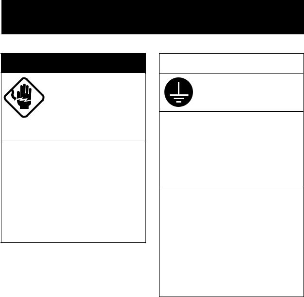
 SAFETY INSTRUCTIONS
 WARNING
Do not open the cover unless totally familiar with electrical circuits.
Hazardous voltage which will cause death or serious injury exists inside the equipment.
Turn off the power at the mains switchboard before beginning the installation. Post a warning sign near the switchboard to indicate that power should not be applied while the equipment is being installed.
Electrical shock, serious injury or fire can result if the power is not turned off or is applied while the equipment is being installed.
 CAUTION
Ground the equipment to prevent electrical shock and mutual interference.
Confirm that the power supply voltage is compatible with the voltage rating of the equipment.
Connection to the wrong power supply can cause fire or equipment damage. The voltage rating appears on the label at the rear of the display unit.
Observe the compass safe disatnce to prevent deviation of a magnetic compass.
|
Standard |
Steering |
|
|
compass |
compass |
|
|
|
|
|
Transceiver |
1.6 m |
1.2 m |
|
Unit |
|||
|
|
||
|
|
|
|
Duplexer |
0.85 m |
0.65 m |
|
Unit |
|||
|
|
||
Power Supply |
0.9 m |
0.7 m |
|
(option) |
|||
|
|

1. System Configuration
VHF |
CH70 RX * |
Antenna |
Antenna |
*: Not used when VHF antenna is commonly used for TX/RX.
DX-8700
DUPLEXER UNIT
Handset
TRANSCEIVER UNIT
External Speaker
FM-8700
Remote Station RB-700
Distributor DB-500
: Standard Supply
: Optional Supply
Navigation Device
Wing Handset (port)
Wing Handset (starboard)
AC/DC |
110/220 VAC |
|
Power |
|
|
Supply |
24 VDC |
|
Unit PR-300 |
||
|
24 VDC
Distress
Message
Controller
DMC-5
Printer
Interface Printer
IF-8500 PP-510
1

2. Equipment Lists
Standard Supply
|
Name |
Type |
Qty |
Mass |
Remarks |
|
(kg) |
||||
|
|
|
|
|
|
|
|
|
|
|
|
1 |
Transceiver Unit |
FM-8700 |
1 |
6 |
|
|
|
|
|
|
|
2 |
Duplexer Unit |
DX-8700 |
1 |
2.7 |
|
|
|
|
|
|
|
3 |
Accessories |
FP05-05100 |
1 Set |
|
See lists at end of |
|
|
|
|
|
manual. |
4 |
Installation |
CP05-07700 |
1 Set |
|
|
|
|
||||
|
Materials |
|
|
|
|
|
|
|
|
|
|
2
Optional Equipment
|
Name |
Type |
|
|
Code No. |
Remarks |
||
|
|
|
|
|
|
|
|
|
1 |
AC-DC Power |
PR-300 |
|
|
|
|
|
|
|
|
|
|
|
|
|||
|
Supply |
|
|
|
|
|
|
|
2 |
VHF Antenna |
RA-106 |
005-374-890 |
|
||||
3 |
Whip Antenna |
150M-W2VN |
000-113-498 |
|
||||
4 |
Antenna Fixing |
4-310071 |
000-572-184 |
|
||||
|
Plate |
|
|
|
|
|
|
|
5 |
Cable Assembly |
05S9192 |
000-139-094 |
|
||||
6 |
Coaxial Cable |
5D-2V *10M* |
000-111-063 |
|
||||
7 |
Coaxial Cable |
5D-2V *20M* |
000-111-064 |
|
||||
8 |
Connector |
M-P-5 |
000-503-678 |
|
||||
9 |
Dynamic Mic Set |
OP05-57 |
000-045-775 |
HS-6000FZ5(Handset) |
||||
10 |
Carbon Mic Set |
OP05-58 |
000-045-776 |
HS-6000FZ6(Handset) |
||||
11 |
Flush Mount Kit |
OP05-73 |
005-386-010 |
|
||||
12 |
Remote Station |
RB-700 |
|
|
|
|
|
|
|
|
|
|
|
|
|||
13 |
Distributor |
DB-500 |
|
|
|
|
|
|
|
|
|
|
|
|
|||
14 |
Twisted Cable |
CO-SPEVV-SB-C |
000-111-680 |
5 m for |
||||
|
|
0.2x2P |
|
|
|
|
|
DMC/NMEA/IF-8500 |
|
|
CO-SPEVV-SB-C |
000-120-792 |
10 m for |
||||
|
|
0.2x2P |
|
|
|
|
|
DMC/NMEA/IF-8500 |
|
|
CO-SPEVV-SB-C |
000-120-793 |
15 m for |
||||
|
|
0.2x2P |
|
|
|
|
|
DMC/NMEA/IF-8500 |
|
|
CO-SPEVV-SB-C |
000-120-794 |
20 m for |
||||
|
|
0.2x2P |
|
|
|
|
|
DMC/NMEA/IF-8500 |
|
|
CO-SPEVV-SB-C |
000-120-214 |
30 m for |
||||
|
|
0.2x2P |
|
|
|
|
|
DMC/NMEA/IF-8500 |
|
|
|
|
|
|
|
|
|
15 |
Printer |
PP-510 |
|
|
|
|
|
|
|
|
|
|
|
|
|||
16 |
Distress Message |
DMC-5 |
|
|
|
|
|
|
|
|
|
|
|
|
|||
|
Controler |
|
|
|
|
|
|
|
|
|
|
|
|
|
|
|
|
17 |
Printer Interface |
IF-8500 |
|
|
|
|
|
|
|
|
|
|
|
|
|||
|
|
|
|
|
||||
18 |
External |
SEM-21Q |
000-144-917 |
|
||||
|
Loudspeaker |
|
|
|
|
|
|
|
|
|
|
|
|
||||
19 |
Connector assy. |
05S9141 |
000-138-998 |
|
||||
|
|
|
|
|
||||
20 |
Bulkhead mount |
OP05-76 |
005-386-470 |
|
||||
|
kit |
|
|
|
|
|
|
|
|
|
|
|
|
|
|
|
|
3

3. Mounting
Transceiver Unit
General mounting considerations
Determine the mounting location for the transceiver unit considering operator convenience, proximity to the power source and the ground location. Keep these and the following points in mind when selecting a mounting location.
•Locate the unit in a place free of water spray and water splash.
•Keep the unit out of direct sunlight because of heat that can build up inside the unit.
•Leave a little slack in cables to allow a service technician to move the radio from its usual location with the cables connected. This
lets him make tuning and other adjustments on a “live” set.
•Do not install the unit where flammable gases are stored.
•Select a well ventilated area.
•Ensure the mounting location is strong enough to support the weight of the unit (6 kg) under the condition of continued vibration nor-
mally encountered aboard the vessel. If necessary, reinforce the mounting area with a doubling plate or lining block.
•Leave sufficient space at the sides and rear of the unit for maintenance and service purposes and to provide for circulation of cooling air. The minimum service clearance appears in Figure 2.
•For flush mounting, select a location where the LCD can be easily viewed.
Note:
Take great care not to press the DISTRESS switch during the installation. If you accidentally press the switch, immediately turn off the equipment and contact appropriate authority by telephone.
4
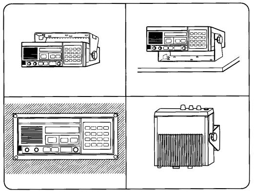
Overview of mounting methods
Overhead |
Tabletop |
Flush Mount |
Bulkhead |
|
Figure 1 Overview of mounting methods
5
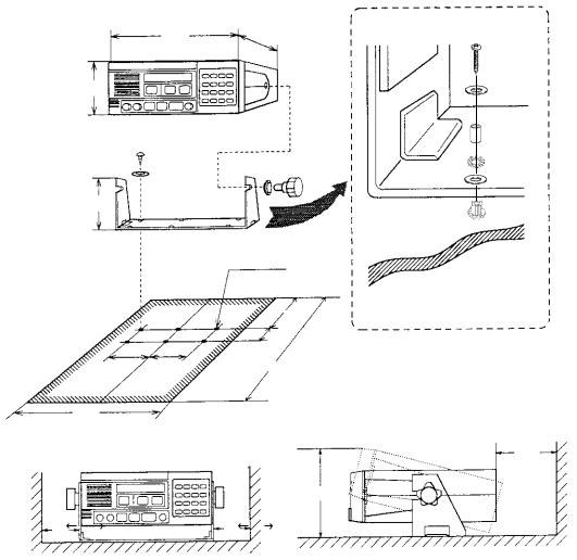
Mounting procedure for tabletop, overhead and bulkhead mounting
1.Using the hanger as a template, mark fixing holes in the mounting location.
2.Fix the hanger to the mounting location with 4 sets of tapping screw, washer, space and two kinds of bushing.
3.Screw the knob bolts with washers into the transceiver unit.
4.Set the transceiver unit to the hanger and tighten knob bolts.
• All dimensions in millimeters.
258 230
108
119
6-φ7.5
150
89
95 |
95 |
394 |
|
|
463
150
155
80 |
80 |
•For added support, fasten hanger with nuts, bolts and washers (local supply) instead of wood screws.
•Leave sufficient space at the sides and rear of the unit to provide easy access for maintenance and service. The mini-
mum service clearance is shown in the figure.
Figure 2 Mounting dimensions for tabletop, overhead and bulkhead mounting
6

The mounting procedure for flush mount (option)
Requires flush mount kit OP05-73 (optional supply). Prepare a cutout in the mounting location whose dimensions are as shown in the Figure 3.
Flush Mount Kit (OP05-73)
No. |
Name |
Type |
Q'ty |
Code No. |
|
|
|
|
|
1 |
Flush mount plate |
05-073-1231 |
1 |
100-239-281 |
|
|
|
|
|
2 |
Tapping screw |
5x20 SUS304 |
4 |
000-802-840 |
|
|
|
|
|
3 |
Hex. screw |
M8x16 |
2 |
000-882-075 |
|
|
|
|
|
261
150 |
|
205 |
|
25 |
max 14 |
|
|
|
|
|
|
|
|
|
|
|
|
|
|
|
|
|
10 |
|
|
10 |
|
|
|
|||
|
|
106 |
20 |
|
|
|
Figure 3 Mounting dimensions for flush mount
Duplexer Unit
General mounting consideration
•Locate the unit in a place free of water spray and water splash.
•Keep the unit out of direct sunlight because of heat that can build up inside the unit.
•Leave a little slack in cables to allow a service technician to move the radio from its usual location with the cables connected. This
lets him make tuning and other adjustments on a "live" set.
•Do not install the unit where flammable gases are stored.
•Select a well ventilated area.
•Ensure the mounting location is strong enough support the weight of the unit (2.7 kg) under the condition of continued vibration nor-
mally encountered aboard the vesssel. If necessay, reinforce the mounting area with a doubling plate or lining block.
• Leave sufficient space at the sides and rear of the unit for maintenance and service purposes and to provide for circulation of cooling air.
Mounting the unit
Mount the unit with four tapping screws supplied.
7
VHF Antenna
The antenna requirements
Any good quality antenna meeting the requirements shown below may be used. A high-gain antenna is preferable.
• |
Frequency range: |
155 to 164 MHz |
• |
Impedance: |
50 ohms |
• |
Polarization: |
Vertical |
• |
Handling power: |
30 W/ min |
• |
Quality: |
Able to withstand marine environment |
Mounting considerations
•The antenna should be well separated from nearby antennas, masts, and other interfering objects.
•The higher the antenna is mounted above the horizon, the further the communications range.
Mounting procedure
The basic mounting procedure for antennas supplied by FURUNO is as follows, however consult appropriate outline drawing for details.
1.Fasten the antenna bracket to the stanchion.
2.Set the antenna to the antenna bracket and tighten bolts.
3.Screw the coaxial cable plug into the antenna.
CH70 Rx Antenna
The antenna should be well separated from nearby antennas, masts, and other interfering objects.
The mounting procedure is the same as that for the VHF antenna, however consult appropriate outline drawing for details.
Handset Hanger
The handset hanger can be mounted at the front or rear of the transceiver unit. To mount the hanger at the rear of the unit, a connector and connector assembly are required (option). The mounting location should provide easy access to front panel controls while operating the handset. Also, the length of the standard handset cable is 50 cm, so locate the handset hanger within 50 cm of the unit. (Longer cables are available optionally.)
8
Power Supply (option)
For Convention vessels, both AC and DC power must be fed to the FM-8700, via an AC/DC power supply. When AC input fails, DC power is supplied. FURUNO can supply an AC/DC power supply unit, the PR-300.
Mounting considerations
When selecting a mounting location, keep in mind the following points.
•Select a location which provides adequate ventilation.
•The location must be clean and dry.
•The mounting location must be able to support the weight of the unit (14.5 kg) under the continued conditions of vibration normally encountered aboard the vessel. If necessary, reinforce the mounting location.
Mounting
Refer to outline drawing.
Printer Interface (option)
Printer Interface IF-8700 is connected between the printer PP-510 and the transceiver unit. See outline drawing on page D-11.
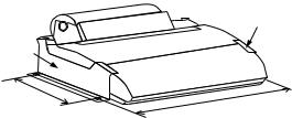
Printer (option)
Refer to the printer outline drawing on page D-12 for mounting dimensions.
Lay the printer on a tabletop and fix it with printer fixtures 1 and 2.
Printer
 Fixture 2
Printer
Fixture 1
200
405
Figure 4 Mounting of Printer PP-510
9
External Loudspeaker (option)
The external loudspeaker can be installed on a tabletop, the overhead or a bulkhead. Fasten the loudspeaker to the mounting location with tapping screw, or nuts, bolts and washers. For mounting dimensions, see the outline drawing on page D-9.
10

4. Connections
Overview
Figure 5 Interconnection
11
Loading...