


AUTOPILOT
NAVpilot-500

 SAFETY INSTRUCTIONS
 WARNING
Do not open the equipment unless you are well familiar with electrical circuits.
Only qualified personnel
ELECTRICAL should work inside the SHOCK equipment.
HAZARD
Do not set the course changing speed too high.
The boat will be turned too sharply at the course change, which could create a very dangerous situation.
Do not use the autopilot in the following situation:
 Harbor entrance or narrow channel
  Where vessels change course often, such as a cape or small island
Observe the following cautions when using the autopilot:
 Maintain a vigilant watch
 Watch for drifting of vessel
In an emergency, manually steer the vessel.
The autopilot cannot avoid vessels, etc. automatically.
Do not use the SIMULATION mode on the boat.
The rudder may move. This is specialpurpose mode for technicians.
WARNING
Do not use the ORBIT mode in rough sea.
Because the boat turns a 360-degree circle around the waypoint a large wave or strong wind can cause the boat to capsize.
Confirm that no objection is in the general vicinity of the waypoint.
The distance from the waypoint to the turning point depends on boat's speed.
Do not use the SIMULATION mode on the boat.
The rudder may move. This is specialpurpose mode for technicians.
 CAUTION
In case of power failure turn off the autopilot or manually steer the vessel.
Leaving the equipment in the AUTO or NAV mode during power failure will cause wear on the rudder mechanism.
Use the correct fuse.
Use of a wrong fuse can cause fire or damage the equipment.
WARNING LABEL
A warning label is attached to the processor unit. Do not remove the label. If the label is missing or damaged, contact your dealer about replacement.
WARNING |
Name: Warning Label (1) |
To avoid electrical shock, do not |
Type: 86-003-1011 |
remove cover. No user-serviceable |
Code No.: 100-236-231 |
parts inside. |
|
i
TABLE OF CONTENTS
|
|
|
...........................................................................................................FORWORD |
iv |
|
SYSTEM CONFIGURATION ................................................................................. |
v |
|
1. PRINCIPLE OF THE AUTOPILOT ................................................................ |
1-1 |
|
Principle of Autopilot .......................................................................................................... |
1-1 |
|
Principle of Operation ........................................................................................................ |
1-2 |
|
2. BASIC OPERATION...................................................................................... |
2-1 |
|
2.1 |
Operating Controls .................................................................................................... |
2-1 |
2.2 |
Turning On/Off........................................................................................................... |
2-2 |
2.3 |
Adjusting Brilliance and Contrast ............................................................................... |
2-3 |
2.4 |
Displays..................................................................................................................... |
2-3 |
|
2.4.1 Selecting the data shown on Normal and Data Displays ................................... |
2-4 |
|
2.4.2 Selecting the display on Graphic Display .......................................................... |
2-7 |
|
2.4.3 Selecting data for analog indicator.................................................................... |
2-8 |
3. STEERING MODES....................................................................................... |
3-1 |
|
3.1 |
STBY Mode ............................................................................................................... |
3-1 |
3.2 |
AUTO Mode .............................................................................................................. |
3-2 |
|
3.2.1 Using the AUTO mode ...................................................................................... |
3-2 |
|
3.2.2 ADVANCED AUTO mode.................................................................................. |
3-3 |
|
3.2.3 TURN mode (For AUTO mode)......................................................................... |
3-4 |
3.3 |
NAV Mode ................................................................................................................. |
3-5 |
|
3.3.1 Starting the NAV mode...................................................................................... |
3-5 |
|
3.3.2 Selecting sailing method of NAV mode ............................................................. |
3-6 |
|
3.3.3 Switching waypoint ........................................................................................... |
3-7 |
|
3.3.4 Selecting boat’s movement at the destination (or last) waypoint ....................... |
3-7 |
|
3.3.5 Navigating to TLL point (FISHING mode)........................................................ |
3-10 |
3.4 |
REMOTE Mode ....................................................................................................... |
3-11 |
3.5 |
DODGE Mode ......................................................................................................... |
3-17 |
|
3.5.1 Dodging in STBY mode .................................................................................. |
3-17 |
|
3.5.2 Dodging in AUTO or NAV mode...................................................................... |
3-18 |
4. MENU OPERATION ...................................................................................... |
4-1 |
|
4.1 |
STBY Mode Menu ..................................................................................................... |
4-1 |
|
4.1.1 Offsetting data .................................................................................................. |
4-1 |
|
4.1.2 Setting parameters ........................................................................................... |
4-3 |
|
4.1.3 Setting the units of measurements.................................................................. |
4-10 |
|
4.1.4 Setting other menu items ................................................................................ |
4-12 |
ii
5. ALARMS........................................................................................................ |
5-1 |
|
5.1 |
ALARM Menu ............................................................................................................ |
5-1 |
|
5.1.1 Selecting the alarm buzzer................................................................................ |
5-2 |
|
5.1.2 Selecting the beep pattern................................................................................. |
5-2 |
|
5.1.3 Setting the watch alarm..................................................................................... |
5-3 |
|
5.1.4 Setting the heading deviation alarm .................................................................. |
5-3 |
|
5.1.5 Setting the cross-track error limit....................................................................... |
5-3 |
|
5.1.6 Setting the speed alarm .................................................................................... |
5-4 |
|
5.1.7 Setting the depth alarm ..................................................................................... |
5-5 |
|
5.1.8 Setting the temperature alarm ........................................................................... |
5-6 |
|
5.1.9 Setting the trip distance alarm ........................................................................... |
5-6 |
|
5.1.10 Clearing the trip distance................................................................................. |
5-7 |
5.2 |
Alarm Information....................................................................................................... |
5-7 |
6. MAINTENANCE & TROUBLESHOOTING |
...................................................6-1 |
|
6.1 |
Preventive Maintenance............................................................................................. |
6-1 |
6.2 |
Replacement of Fuse................................................................................................. |
6-2 |
6.3 |
Diagnostics ................................................................................................................ |
6-2 |
6.4 |
Clearing Memories..................................................................................................... |
6-6 |
6.5 |
Error Messages.......................................................................................................... |
6-7 |
MENU TREE................................................................................................... |
MN-1 |
|
SPECIFICATIONS |
|
|
iii

FOREWORD
A Word to the Owner of the NAVpilot-500
Congratulations on your choice of the FURUNO NAVpilot-500 AUTOPILOT.
For over 50 years FURUNO Electric Company has enjoyed an enviable reputation for innovative and dependable marine electronics equipment. This dedication to excellence is furthered by our extensive global network of agents and dealers.
Your autopilot is designed and constructed to meet the rigorous demands of the marine environment. However, no machine can perform its intended function unless installed, operated and maintained properly. Please carefully read and follow the recommended procedures for operation and maintenance.
We would appreciate hearing from you, the end-user, about whether we are achieving our purposes.
Thank you for considering and purchasing FURUNO equipment.
Features
•Self learning program to continuously improve the steering parameters for safe and expeditious navigation
•Two steering modes – AUTO (Heading Control System) and NAV (Track Control System)
•Dodging from the control unit or remote controller
•Available for solenoid drive and reversible hydraulic
•Max. six control units may be connected (using two ports of the processor unit)
•Menu operation for simplified control
•Display modes: Autopilot/Track control modes with rudder angle, L/L, Highway, Two customized displays, compass rose
iv
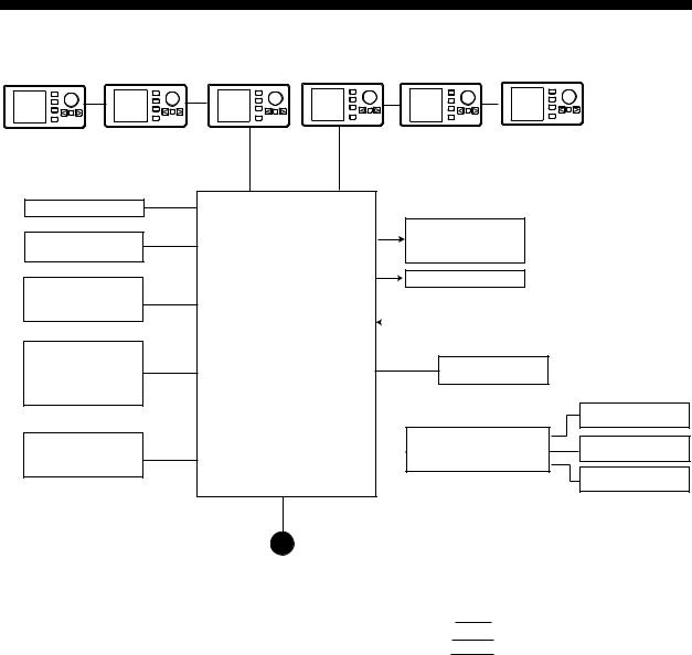
SYSTEM CONFIGURATION
PC
Heading sensor PG-500
External buzzer
GPS Navigator (NMEA0183)
RD-30 (Max. 3)
(NMEA0183)
Control Unit
FAP-5001 (Max. 6)
Processor Unit
FAP-5002
Ship’s mains 12-24 VDC
|
Reversible pump or |
|
Ship’s steering system |
|
|
Electromagnetic valve unit |
|||
|
|
|||
|
Clutch |
|
||
|
|
|
|
|
|
Rudder Reference Unit |
|
|
|
|
FAP-6111 |
|
|
|
|
|
|
|
|
|
|
|
|
|
|
Remote Controller |
|
||
Remote Controller
Distributor FAP-6800 |
Remote Controller |
Remote Controller
Remote controler
Dial type: FAP-5551, FAP-5552
Button type: FAP6211, FAP-6212
Lever type: FAP-6221, 6222
Dodge type: FAP-6231, 6232
:Standard supply
:Option
:User supply
System configuration of NAVpilot-500
v
This page is intentionally left blank.
vi

1.PRINCIPLE OF THE AUTOPILOT
Principle of Autopilot
Autopilot is an automatic device for steering a vessel maintaining its heading in an intended direction. Anyone can appreciate the advantages of the autopilot – being free to carry out navigational checks, trim adjustments or simply to relax and enjoy.
The autopilot utilizes a proportional rate system to steer the boat. The proportional rate system is similar to the highly accurate and reliable system used on aircraft, missiles and space vehicles. The proportional rate autopilot provides the necessary course correction to the steering gears in proportion to the speed and amount the boat moves off course.
With the removal of the dead band, the autopilot no longer wanders within a dead band but now steers a prescribed course, taking action within the presence of even a minute course error. The amount of action depends on the course error detected; that is, when the course error rate is small a very low helm correction rate is applied.
Because the wandering is eliminated, the proportional rate autopilot has the advantages of low power consumption and low wear and tear on the autopilot and the steering system. Off-course correction is smooth, not jerking back and forth at full speed.
1-1
1. PRINCIPLE OF THE AUTOPILOT
Principle of Operation
In the AUTO modes, the heading information from an associated sensor is continuously compared with the set course (in the NAV mode, the course to the waypoint set on the plotter connected). With the boat on course, the two signals are equal.
If the boat goes off course, the difference between the primary heading and the set course will change proportionally and there will be an imbalance at the comparator, whose output will move up or down depending on whether the course error is to the left or right of the set course.
The rudder continues to move until a balanced condition is obtained at the comparator, at which point the drive switches off.
To set the rudder when the boat is off-course, the rudder signal is generated at the rudder reference unit, then delivered the processor unit.
1-2
2.BASIC OPERATION
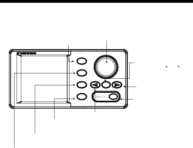
2.1Operating Controls
Enter knob
Rotate: Selects menu items and options.
STBY key Push: Sets the course on Auto or Nav mode.
Selects the STBY (manual) mode.
STBY |
|
Turn key |
|
|
|
|
|
Turns the boat 180 or 360 . |
AUTO |
|
|
NAV |
TURN |
Starboard key |
|
|
Steers the rudder to boat. |
MENU |
|
POWER/BRILL key |
|
|
|
|
|
Long press: Turns power off. |
|
|
Mormentary press: Turns power on; |
|
Port key |
opens the display for adjustment of |
MENU key |
Steers the boat to port. |
brilliance and contrast. |
|
|
|
Opens the mode menus. |
|
|
NAV key |
|
|
Selects the NAV mode. |
|
|
AUTO key |
|
|
Selects the AUTO mode. |
|
|
Control unit, front view
2-1
2. BASIC OPERATION
2.2Turning On/Off
Press the [POWER/BRILL] key to turn the unit on before leaving the port, because several minutes are necessary to allow for stabilization of the heading data from the heading sensor. (For PG-500, see Note 2 shown below.) A beep sounds and the equipment proceeds in the sequence shown below, displaying product information and startup test results. The startup test checks the ROM, RAM, backed up data and communication between the control unit and processor unit for proper operation. Also it checks the inputs of heading signal and rudder angle signal for the processor unit. If NG appears an appropriate message appears on the screen. For any NG, try to press any key to go to the next screen. However, the equipment may not work properly. Contact your dealer for advice.
AUTO PILOT NAVPILOT-500
FURUNO ELECTRIC CO., LTD
START UP TEST |
|
|
|
ROM |
|
|
|
PROCESSOR |
OK 6454002-**.** |
||
CONTROL |
OK 6454001-**.** |
||
RAM |
|
|
|
PROCESSOR UNIT |
OK |
||
CONTROL UNIT |
|
OK |
|
BACK UP DATA |
|
|
|
PROCESSOR UNIT |
OK |
||
CONTROL UNIT |
|
OK |
|
HEADING DATA |
OK 359.9 |
||
|
6454101-**.** |
|
|
RRU |
OK P12.3 |
||
CONTROLLER ID |
|
1 |
|
**.** : Program version no.
Startup sequence
After the startup test is completed, “STBY” appears on the screen. This means the equipment may now be operated manually.
Note 1: The first time you turn on the power, you are asked if you want to start the simulation mode, which provides simulated operation of the equipment. Push the [ENTER] knob to start the simulation mode, or any key to escape. If you pressed a key except the [ENTER] knob, you are asked if you want to set the installation menu. Press the [ENTER] knob to go to the installation menu, or any key to go to STBY. For details about the installation menu, contact your dealer.
Note 2: When the Integrated Heading Sensor PG-500 is connected, press the [POWER/BRILL] key four minutes before leaving the port to use the AUTO mode which needs stabilized bearing data.
Turning the power off
Press and hold down the [POWER/BRILL] key until the screen goes blank. The time remaining until the power is turned off is shown on the screen.
2-2
2. BASIC OPERATION
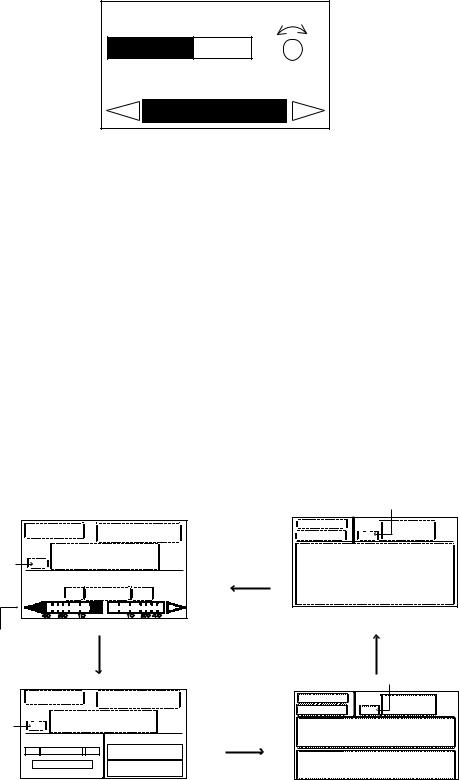
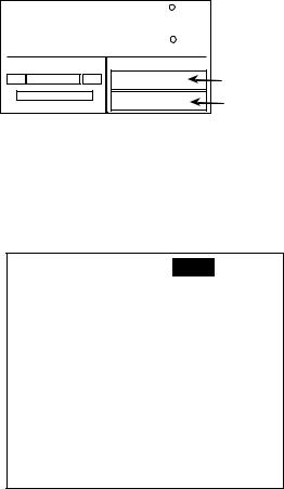
2.3Adjusting Brilliance and Contrast
The brilliance and contrast can be adjusted as below:
1.Momentarily press the [POWER/BRILL] key. The CONTRAST and BRILL window appears.
CONTRAST |
10 |
BRILL |
8 |
PORT |
STBD |
Contrast, brilliance window
2.Rotate the [ENTER] knob to adjust display contrast; clockwise to raise the contrast and counter-clockwise to lower it. (16 levels are available.)
The contrast can also be adjusted by pressing the [POWER/BRILL] key.
3.Press the [PORT] or [STBD] key to adjust display brilliance, [PORT] to lower the brilliance and [STBD] to raise it. (Eight levels are available.)
To close the CONTRAST and BRILL window, press any key except the [POWER/BRILL], [STBD] or [PORT] key.
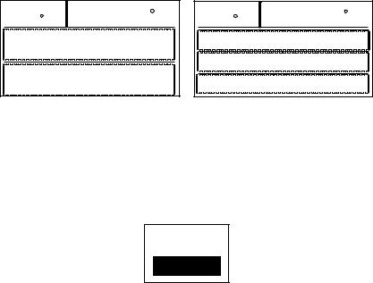
2.4Displays
There are four types of displays: Normal display 1, Normal display 2, Graphic display and Data display.
To choose a display mode, press a mode key (AUTO, NAV, STBY). Each time a mode key is pressed the display changes in the sequence shown below.
(Mode) |
|
(Course) |
|
HDG |
|
(Heading) |
|
Heading mode |
|
|
|
|
|
|
|
|
P |
(Data) |
S |
Analog indicator |
(Normal display 1) |
||
|
|
|
|
(Mode) |
|
(Course) |
|
|
|
|
|
HDG |
|
(Heading) |
|
Heading mode |
|
|
|
|
|
|
|
P |
(Data) |
S |
(Data1) |
|
|
|
(Data 2) |
(Normal display 2)
Heading mode
(Mode) |
HDG |
|
(Course) |
||
|
||
|
(Graphic) |
(Graphic display)
|
|
Heading mode |
|
(Mode) |
HDG |
(Heading) |
|
(Course) |
|||
|
|
(Data1)
(Data 2)
(Data display)
Displays
2-3
2. BASIC OPERATION
2.4.1Selecting the data shown on Normal and Data Displays
Some display modes may be set up to suit your operating needs, on the SCREEN SETUP menu.
Selecting data for Normal Display 2 screen
You can select the data to show on the upper and lower half of the Normal Display 2.
STBY 20.5
|
HDG |
|
145.9 |
|
P |
(Data) |
S |
(Data1) |
Upper half |
|
|
|
(Data 2) |
Lower half |
Normal Display 2
1.Press the [STBY] and [MENU] key in order to show the STBY menu.
2.Rotate the [ENTER] knob to select the SCREEN SETUP, and then press the [ENTER] knob to show the SCREEN SETUP menu.
SCREEN2 UPPER DATA: POS
SCREEN2 LOWER DATA:
SCREEN3 PATTERN: 3 DATA
DATA1: POS
DATA2: COG
DATA3: SOG
GRAPHIC:
HIGHWAY
Screen setup menu
3.Rotate the [ENTER] knob to select “SCREEN 2 DATA UPPER” or “SCREEN 3 DATA LOWER” from the SCREEN SETUP menu.
4.Press the [ENTER] knob to show the options window.
5.Rotate the [ENTER] knob to select the data which you want to show on the upper or lower half of the Normal Display 2.
2-4
|
2. BASIC OPERATION |
Data available for display in SCREEN 2 UPPER and LOWER |
|
Menu option |
Displayed data |
|
|
POS |
Own ship’s position (L/L) |
|
|
COG |
Course over ground |
|
|
SOG |
Speed over ground |
|
|
STW |
Speed through water |
|
|
TMP |
Water temperature |
|
|
DPT |
Depth |
|
|
BRG |
Bearing to waypoint |
|
|
RNG |
Range to waypoint |
|
|
WPT POS |
Waypoint position (L/L) |
|
|
XTE |
Cross-track error |
|
|
TTG |
Time-to-Go to Destination |
|
|
ETA |
Estimated Time of Arrival |
|
|
DATE |
Date |
|
|
TIME |
Time |
|
|
WIND T* |
Wind direction and speed (True) |
|
|
WIND R** |
Wind direction and speed (Relative) |
|
|
VOLT |
Input/output power voltage to the processor unit |
|
|
TRIP |
Trip distance |
|
|
*True: |
The speed and direction (in relation to ship’s bow) of the wind felt |
|
or measured when stationary. |
**Relative: |
The direction (in relation to ship’s bow) and speed of the wind as it |
|
appears to those on board, relative to the speed and direction of |
|
the boat; combination of the true wind and the wind caused by the |
|
boat’s movement. |
6.Press the [ENTER] knob.
7.Press the [MENU] key to close the menu.
2-5
2. BASIC OPERATION
Selecting the display layout for Data Display
You can show two or three data on the Data Display.
STBY
20.4HDG 116.5
(Data1)
(Data 2)
Data display, two data
STBY
20.4HDG 116.5
(Data1)
(Data 2)
(Data 3)
Data display, three data
Data Displays
1.Open the SCREEN SETUP menu referring to page 2-4.
2.Rotate the [ENTER] knob to select “SCREEN 3 PATTERN.
3.Press the [ENTER] knob to show the screen 3 options window.
2 DATA
3 DATA
Screen 3 pattern options window
4.Rotate the [ENTER] knob to select 2 DATA or 3 DATA as appropriate.
5.Press the [ENTER] knob.
6.Press the [ENTER] knob to close the menu.
Selecting data for Data Display
You may choose which data to show on the Data Display. Data 3 is available only when you select 3DATA at “SCREEN 3 PATTERN” shown above.
1.Open the SCREEN SETUP menu referring to the page 2-5.
2.Rotate the [ENTER] knob to select “DATA 1”, “DATA 2” or “DATA 3”.
3.Press the [ENTER] knob show the option window.
The contents are same as the table shown on the previous page.
4.Rotate the [ENTER] knob to select data.
5.Press the [ENTER] knob.
6.Press the [MENU] key to close the menu.
2-6
2. BASIC OPERATION
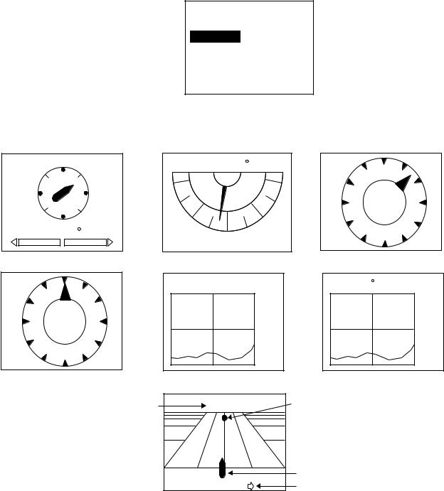
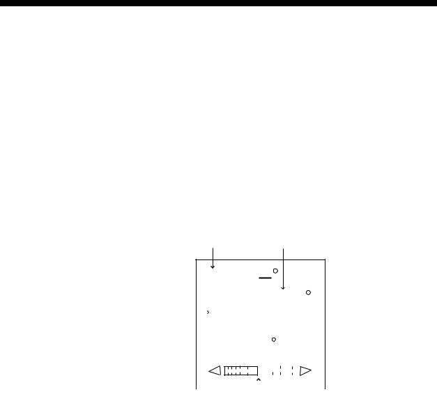
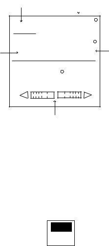
2.4.2Selecting the display on Graphic Display
COMPASS, RUDDER ANGLE, HIGHWAY, WIND TRUE INDICATOR, WIND RELATIVE INDICATOR, DEPTH GRAPH or TEMP GRAPH can be shown on the Graphic Display. Note that the appropriate sensors are necessary to display data.
1.Open the SCREEN SETUP menu referring to page 2-4.
2.Rotate the [ENTER] knob to select “GRAPHIC”.
3.Press the [ENTER] knob to show the graphic options window.
COMPASS
RUDDER ANGLE
HIGHWAY
WIND TRUE INDICATOR
WIND RELATIVE INDICATOR
DEPTH GRAPH
TEMP GRAPH
Graphic options window
4. Rotate the [ENTER] knob to select the graphic type.
|
N |
W |
E |
|
S |
RUDDER |
P 2.5 |
|
COMPASS |
WIND |
RELATIVE |
45
12 kt
RUDDER ANGLE P 5.1 |
WIND |
TRUE |
|
|
45
12 kt
PORT |
STBD |
|
RUDDER ANGLE |
|
TRUE WIND INDICATOR |
DEPTH 260ft |
|
TEMP 32.0 F |
|
200 |
40 |
300 |
30 |
RELATIVE WIND INDICATOR |
DEPTH GRAPH |
TEMP GRAPH |
Waypoint ID |
001WPT |
Waypoint mark |
|
||
|
|
Own ship symbol |
|
P0.01 nm |
Direction to steer |
|
HIGHWAY |
|
Graphic displays
5. Press the [ENTER] knob and [MENU] key in order to close the menu.
2-7
2. BASIC OPERATION
2.4.3Selecting data for analog indicator
Choose what to display on the analog indicator display on Normal Display 1 and 2.
(Mode) |
(Course) |
(Mode) |
(Course) |
HDG |
(Heading) |
HDG |
(Heading) |
P |
(Data) |
P |
(Data) |
S |
(Data1) |
S |
|
|
(Data 2) |
||
|
|
|
|
|
(Normal display 1) |
|
|
|
|
(Normal display 2) |
|
|||||
|
|
|
|
|
|
|
|
|
Analog indicator |
|
|
|
|
|
|||
|
|
|
|
Normal Display 1 and 2
1.Press the [STBY] and [MENU] key in order to show the STBY menu.
2.Rotate the [ENTER] knob to select “DISPLAY SETUP”.
3.Press the [ENTER] knob to show the DISPLAY SETUP menu.
SPEED UNIT: |
kt |
|
RANGE UNIT: |
nm |
|
WIND SPEED UNIT: |
kt |
|
DEPTH UNIT: |
ft |
|
WATER TEMP UNIT: |
F |
|
POSITION FORMAT |
|
|
DD MM. MMM"
 NEXT PAGE
Page 1
 PREVIOUS PAGE
HEADING READOUT: MAGNETIC
SPEED READOUT: SOG
ANALOG INDICATOR BAR:
RUDDER ANGLE
DATE FORMAT: MMM. DD. YYYY
TIME FORMAT: 24HOUR
Page 2
Display setup menu
To change pages, select “▼NEXT PAGE” or “▲PREVIOUS PAGE” and press the [ENTER] knob.
2-8

2. BASIC OPERATION
4.Rotate the [ENTER] knob to select “ANALOG INDIACATOR BAR” on the second page.
5.Press the [ENTER] knob to show the bar indicator options window.
RUDDER ANGLE
DEVIATION
RUDDER/XTE
DEVIATION/XTE
Analog indicator bar options window
6.Rotate the [ENTER] knob to select option you desired to show.
Note the following.
RUDDER/XTE: Rudder in STBY and AUTO mode, XTE in NAV mode. DEVIATION/XTE: Deviation in STBY and AUTO mode, XTE in NAV mode.
7.Press the [ENTER] knob.
8.Press the [MENU] key to close the menu.
2-9
2. BASIC OPERATION
This page is intentionally left blank.
2-10
3.STEERING MODES
The NAVpilot-500 system is capable of five primary steering modes: STBY (manual), AUTO, NAV, REMOTE (FU and NFU) and DODGE.
In case of emergency, for example, collision avoidance, turn the helm quickly to control the boat manually. The alarm sounds and “STBY” flashes on the display. To return to the normal mode, press the [STBY], [AUTO] or [NAV] mode.
3.1STBY Mode
After turning on the power, the equipment goes to the STBY mode.
This is a manual steering mode. When sailing out of a harbor, steer the vessel in the STBY mode.
Press the [STBY] key.
STBY mode |
Heading from heading sensor |
(manual steering mode) |
STBY
|
|
|
|
M |
|
359.9 |
|
|||||||||
Heading mode |
|
|
HDG |
|
|
|
|
|
|
|
|
|
|
|
|
|
|
|
|
|
|
|
|
|
|
|
|
|
|
|
|
|
|
M: Magnetic |
|
|
|
|
|
|
|
|
|
|
|
|
|
|
|
|
|
RUDDER |
|
0 |
|
|
|
|
|
|
|||||||
T: True |
|
|
|
|
|
|
|
|
||||||||
|
|
|
|
|
|
|
|
|
|
|
||||||
|
|
|
|
|
|
|
|
|
|
|
|
|
||||
|
|
|
|
20 |
|
|
|
|
|
|
|
|
|
|
||
|
|
|
|
|
|
|
|
|
|
|
|
|
|
|
|
|
|
|
|
|
|
|
|
|
|
|
|
|
|
|
|
|
|
|
|
40 |
10 |
|
|
10 |
20 |
40 |
|
|||||||
|
|
|
|
|||||||||||||
|
|
|
|
|
|
|
|
|
|
|
|
|
|
|
|
|
|
|
|
|
|
|
|
|
|
|
|
|
|
|
|
|
|
Rudder angle (or Deviation)
STBY mode display
3-1
3. STEERING MODES
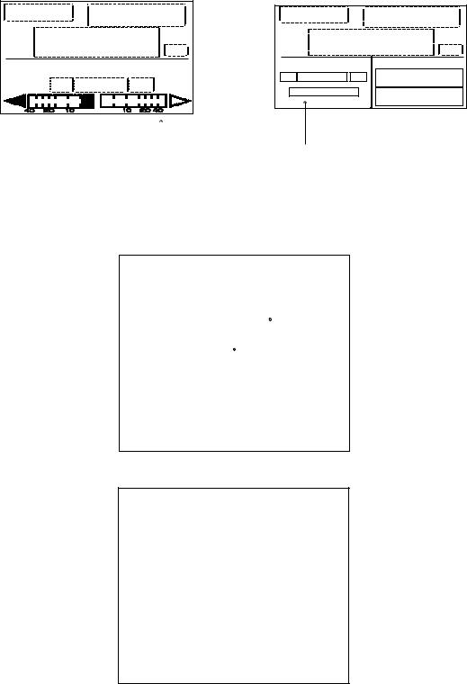
3.2AUTO Mode
3.2.1Using the AUTO mode
The AUTO mode makes the NAVpilot-500 steer the boat automatically on a set course.
Note: The AUTO mode will not bring your boat to the destination when wind or tide prevails. Use this mode for a short straight voyage. Otherwise switch to the NAV mode shown on page 3-5.
1.Direct the boat to the intended course desired.
The course in this mode is a line connecting between the origin and the destination.
2.Press the [AUTO] key to access the Auto mode.
Your boat will automatically be steered toward the course at the moment the [AUTO] key is pressed.
Whenever the heading deviates from the set course, the NAVpilot-500 automatically adjusts the rudder to return the boat to the set course.
3.To change or readjust the course setting in the AUTO mode, simply rotate the [ENTER] knob to set the desired course.
4.Press the [STBY] key to leave AUTO steering in an emergency. You can steer your boat by the helm.
Heading control mode |
Course selected by the [ENTER] knob |
|
(AUTO mode) |
|
|
|
|
|
|
|
|
|
AUTO |
359 |
|
M: Magnetic |
M |
359.9 |
|
Heading mode |
HDG |
|
|
RUDDER |
|
||
T: True |
0 |
||
|
|||
|
|
 Heading from heading sensor
40 20 10  10 20 40
Rudder angle (or Deviation)
AUTO mode display
3-2
3. STEERING MODE
3.2.2ADVANCED AUTO mode
AUTO mode maintains set course but the track may be shifted by current or wind. ADVANCED AUTO mode maintains set course without deviating from the track. This mode can be enabled by connecting a navaid which can output own ship’s position data (L/L) in NMEA0183 format to the NAVpilot-500.
After connecting to a navaid which outputs position data, press the [AUTO] key. The NAVpilot-500 calculates the course based on the present position and heading. In this mode, “AUTO” appears on the display.
ADVANCED AUTO |
Course selected by the [ENTER] knob |
|
(Indicated with underline) |
|
|
|
|
|
|
|
|
Heading mode M: Magnetic T: True
AUTO |
|
359 |
|
|||
HDG |
|
359.9 |
Heading from |
|||
M |
|
|||||
|
heading sensor |
|||||
RUDDER |
|
|
0 |
|
|
|
|
|
|
|
|
|
|
40 |
20 |
10 |
10 |
20 |
40 |
|
Rudder angle ( or XTE)
ADVANCED AUTO mode display
Enabling the ADVANCED AUTO mode
You can select whether to use the ADVANCED AUTO mode or not as follows.
1.In the AUTO mode, press the [MENU] key to show the AUTO mode menu.
2.Rotate the [ENTER] knob to select “ADVANCED AUTO”, and then press the [ENTER] knob to show the advanced auto options window.
OFF
ON
Advanced auto options window
3.Rotate the [ENTER] knob to select “ON”.
When you want to finish the ADVANCED AUTO mode, select “OFF”.
4.Press the [ENTER] knob, [MENU] key in order close the menu.
3-3
 Loading...