


OPERATOR'S MANUAL
GPS NAVIGATOR
Model
GP-170
www.furuno.com

The paper used in this manual is elemental chlorine free.
FURUNO Authorized Distributor/Dealer
9-52 Ashihara-cho,
Nishinomiya, 662-8580, JAPAN
All rights reserved. |
Printed in Japan |
A : JUN . 2014
Pub. No. OME-44820-A
(YOTA ) GP-170
0 0 0 1 7 7 7 3 6 1 0

IMPORTANT NOTICE
General
•This manual has been authored with simplified grammar, to meet the needs of international users.
•The operator of this equipment must read and follow the descriptions in this manual. Wrong operation or maintenance can cancel the warranty or cause injury.
•Do not copy any part of this manual without written permission from FURUNO.
•If this manual is lost or worn, contact your dealer about replacement.
•The contents of this manual and equipment specifications can change without notice.
•The example screens (or illustrations) shown in this manual can be different from the screens you see on your display. The screens you see depend on your system configuration and equipment settings.
•Save this manual for future reference.
•Any modification of the equipment (including software) by persons not authorized by FURUNO will cancel the warranty.
•All brand and product names are trademarks, registered trademarks or service marks of their respective holders.
How to discard this product
Discard this product according to local regulations for the disposal of industrial waste. For disposal in the USA, see the homepage of the Electronics Industries Alliance (http://www.eiae.org/) for the correct method of disposal.
How to discard a used battery
Some FURUNO products have a battery(ies). To see if your product has a battery(ies), see the chapter on Maintenance. Follow the instructions below if a battery(ies) is used. Tape the + and - terminals of battery before disposal to prevent fire, heat generation caused by short circuit.
In the European Union
The crossed-out trash can symbol indicates that all types of batteries |
|
|
must not be discarded in standard trash, or at a trash site. Take the |
|
|
used batteries to a battery collection site according to your national |
Cd |
|
legislation and the Batteries Directive 2006/66/EU. |
||
|
||
In the USA |
|
The Mobius loop symbol (three chasing arrows) indicates that Ni-Cd |
|
|
and lead-acid rechargeable batteries must be recycled. Take the |
|
|
used batteries to a battery collection site according to local laws. |
Ni-Cd |
Pb |
|
In the other countries
There are no international standards for the battery recycle symbol. The number of symbols can increase when the other countries make their own recycle symbols in the future.
i

SAFETY INSTRUCTIONS
|
|
|
|
|
|
|
|
|
|
|
|
|
|
|
|
WARNING |
Indicates a condition that can cause death or serious |
|
|
|
|
|
injury if not avoided. |
|
|
|
|
|
|
|
|
|
|
|
|
|
CAUTION |
Indicates a condition that can cause minor or moderate |
|||
|
|
injury if not avoided. |
|
|
|
|
|
|
|
|
|
|
|
|
|
Warning, Caution |
Prohibitive Action |
Mandatory Action |
|
|
|
|
|
|
|
|
|
 WARNING
Do not disassemble or modify the equipment.
Fire, electrical shock or serious injury can occur.
Turn off the power immediately if water leaks into the equipment or smoke or fire is coming from the equipment.
Failure to turn off the equipment can cause fire or electrical shock. Contact a FURUNO agent for service.
Use the correct fuse.
A wrong fuse can cause fire or serious damage to the equipment.
 CAUTION
The glass of an LCD panel breaks easily. Handle the LCD carefully.
Injury can result if the glass breaks.
Do not connect/disconnect the signal cable while turning the power on.
The unit may be damaged.
No single navigation aid (including this unit) should ever be relied upon as the exclusive means for navigating your vessel.
The navigator is responsible for checking all aids available to confirm his position. Electronic aids are intended to assist, not replace, the navigator.
About the TFT LCD
The TFT LCD is constructed using the latest LCD techniques, and displays 99.99% of its pixels. The remaining 0.01% of the pixels may drop out or blink, however this is not an indication of malfunction.
Caution Label(s)
Caution label(s) is(are) attached to the equipment. Do not remove the label(s). If a label is missing or damaged, contact a FURUNO agent or dealer about replacement.
Name: Caution Label
Type: 20-035-1003-0
Code No.: 100-386-200-10
ii
TABLE OF CONTENTS
|
|
|
|
|
...................................................................................................................FOREWORD |
|
vi |
||
SYSTEM CONFIGURATIONS....................................................................................... |
vii |
|||
1. |
OPERATIONAL OVERVIEW................................................................................. |
1-1 |
||
|
1.1 |
Controls ...................................................................................................................... |
1-1 |
|
|
1.2 |
How to Turn the Power On/Off ................................................................................... |
1-3 |
|
|
1.3 |
How to Adjust the Brilliance of the Display and Panel................................................ |
1-4 |
|
|
1.4 |
How to Select the Display Mode................................................................................. |
1-5 |
|
|
1.5 |
Main Menu Overview.................................................................................................. |
1-8 |
|
|
1.6 |
List Overview .............................................................................................................. |
1-9 |
|
|
1.7 |
Context Menu Overview ........................................................................................... |
1-10 |
|
2. PLOTTER DISPLAY OVERVIEW, TRACK ........................................................... |
2-1 |
|||
|
2.1 |
How to Set the Display ............................................................................................... |
2-1 |
|
|
|
2.1.1 |
How to select the background color ............................................................... |
2-1 |
|
|
2.1.2 |
How to zoom in or out the display .................................................................. |
2-1 |
|
|
2.1.3 |
How to change the display orientation ........................................................... |
2-1 |
|
|
2.1.4 |
How to turn the cursor on/off, change cursor size.......................................... |
2-2 |
|
|
2.1.5 |
How to move the cursor ................................................................................. |
2-2 |
|
|
2.1.6 |
How to shift the display .................................................................................. |
2-2 |
|
|
2.1.7 |
How to center the cursor position or ship's position ....................................... |
2-3 |
|
|
2.1.8 |
How to show or hide the grid and change its color......................................... |
2-3 |
|
|
2.1.9 |
How to show or hide the XTL line and change its color ................................. |
2-3 |
|
|
2.1.10 |
How to show or hide the heading line and change its color ........................... |
2-4 |
|
|
2.1.11 |
How to set the COG vector ............................................................................ |
2-4 |
|
|
2.1.12 |
How to display the time mark ......................................................................... |
2-5 |
|
|
2.1.13 |
How to display the names for marks and waypoints ...................................... |
2-5 |
|
|
2.1.14 |
How to show or hide the weather data ........................................................... |
2-5 |
|
2.2 |
Bearing Reference...................................................................................................... |
2-6 |
|
|
|
2.2.1 |
How to select bearing reference..................................................................... |
2-6 |
|
|
2.2.2 |
How to set the magnetic variation .................................................................. |
2-6 |
|
2.3 |
About Tracks .............................................................................................................. |
2-7 |
|
|
|
2.3.1 |
How to start or stop plotting and recording of the track.................................. |
2-7 |
|
|
2.3.2 |
How to set the track plotting interval .............................................................. |
2-7 |
|
|
2.3.3 |
How to set the track color............................................................................... |
2-8 |
|
|
2.3.4 |
How to erase the track ................................................................................... |
2-8 |
3. |
MARKS .................................................................................................................. |
|
3-1 |
|
|
3.1 |
How to Enter a Mark on the Plotter Display................................................................ |
3-1 |
|
|
|
3.1.1 |
How to preset mark appearance .................................................................... |
3-1 |
|
|
3.1.2 |
How to enter a mark at the cursor position..................................................... |
3-2 |
|
|
3.1.3 |
How to enter a mark from the mark list .......................................................... |
3-2 |
|
3.2 |
How to Enter an Event Mark....................................................................................... |
3-5 |
|
|
|
3.2.1 |
How to preset event mark appearance .......................................................... |
3-5 |
|
|
3.2.2 |
How to enter an event mark at own ship’s position ........................................ |
3-5 |
|
|
3.2.3 |
How to enter an event mark from the mark list............................................... |
3-5 |
|
3.3 |
How to Enter a MOB Mark on the Plotter Display ...................................................... |
3-6 |
|
|
3.4 |
How to Edit a Mark or an Event Mark......................................................................... |
3-7 |
|
|
3.5 |
How to Erase Marks ................................................................................................... |
3-8 |
|
4. |
ROUTES ................................................................................................................ |
|
4-1 |
|
|
4.1 |
How to Create a Route ............................................................................................... |
4-1 |
|
iii
TABLE OF CONTENTS |
|
|||
|
|
4.1.1 How to preset the settings for routes ............................................................. |
4-1 |
|
|
|
4.1.2 How to create a new route with the cursor and the ROUTE key.................... |
4-3 |
|
|
|
4.1.3 How to create a new route from the route list ................................................ |
4-4 |
|
|
4.2 |
How to Edit a Route ................................................................................................... |
4-6 |
|
|
|
4.2.1 How to change the route name or color ......................................................... |
4-6 |
|
|
|
4.2.2 How to edit a waypoint in a route................................................................... |
4-7 |
|
|
|
4.2.3 How to temporarily deselect a waypoint in a route......................................... |
4-8 |
|
|
|
4.2.4 How to delete a waypoint from a route........................................................... |
4-9 |
|
|
|
4.2.5 How to insert a waypoint in a route .............................................................. |
4-10 |
|
|
|
4.2.6 How to change the route direction ............................................................... |
4-11 |
|
|
|
4.2.7 How to copy the route .................................................................................. |
4-11 |
|
|
4.3 |
How to Erase a Route .............................................................................................. |
4-12 |
|
5. |
DESTINATION ....................................................................................................... |
5-1 |
||
|
5.1 |
How to Set a Destination............................................................................................ |
5-1 |
|
|
|
5.1.1 How to set a cursor position as a destination................................................. |
5-1 |
|
|
|
5.1.2 How to set a waypoint as a destination.......................................................... |
5-1 |
|
|
|
5.1.3 How to set a registered mark as a destination............................................... |
5-2 |
|
|
|
5.1.4 How to set a registered route as a destination............................................... |
5-3 |
|
|
5.2 |
How to Cancel a Destination...................................................................................... |
5-3 |
|
|
|
5.2.1 How to cancel a destination with the GO TO key........................................... |
5-3 |
|
|
|
5.2.2 How to cancel a destination from the main menu .......................................... |
5-3 |
|
|
|
5.2.3 How to cancel a destination from the context menu ...................................... |
5-4 |
|
|
5.3 |
How to Calculate the Distance, Bearing and TTG (Time To Go) |
|
|
|
|
Between Two Points .................................................................................................. |
5-4 |
|
|
5.4 |
How to Display the ETA and TTG .............................................................................. |
5-5 |
|
|
5.5 |
How to Calculate the Trip Distance............................................................................ |
5-6 |
|
|
5.6 |
How to Set the Drift .................................................................................................... |
5-6 |
|
6. |
NOTICES................................................................................................................ |
|
6-1 |
|
|
6.1 |
Audio Notice Type...................................................................................................... |
6-1 |
|
|
6.2 |
Arrival/Anchor Notice ................................................................................................. |
6-2 |
|
|
|
6.2.1 |
Arrival notice .................................................................................................. |
6-2 |
|
|
6.2.2 |
Anchor notice ................................................................................................. |
6-2 |
|
6.3 |
XTE Notice ................................................................................................................. |
6-3 |
|
|
6.4 |
Ship Speed Notice ..................................................................................................... |
6-3 |
|
|
6.5 |
Trip Notice.................................................................................................................. |
6-4 |
|
7. |
DISPLAYS.............................................................................................................. |
|
7-1 |
|
|
7.1 |
Integrity Display.......................................................................................................... |
7-1 |
|
|
7.2 |
Highway Display......................................................................................................... |
7-4 |
|
|
7.3 |
Course Display........................................................................................................... |
7-5 |
|
|
7.4 |
Data Display............................................................................................................... |
7-6 |
|
8. |
ALERTS ................................................................................................................. |
|
8-1 |
|
|
8.1 |
Overview .................................................................................................................... |
8-1 |
|
|
8.2 |
Alert List ..................................................................................................................... |
8-3 |
|
|
8.3 |
Alert Log..................................................................................................................... |
8-4 |
|
|
8.4 |
How to Acknowledge Alerts ....................................................................................... |
8-4 |
|
9. |
OTHER FUNCTIONS ............................................................................................. |
9-1 |
||
|
9.1 |
Unit Setup Menu ........................................................................................................ |
9-1 |
|
|
9.2 |
Correction, Offset Menu ............................................................................................. |
9-1 |
|
|
9.3 |
GNSS Menu ............................................................................................................... |
9-4 |
|
|
|
9.3.1 How to select the positioning system ............................................................. |
9-4 |
|
|
|
9.3.2 How to set the time for smoothing of position, speed and speed average..... |
9-4 |
|
iv
|
|
TABLE OF CONTENTS |
|
9.3.3 How to set the positioning condition............................................................... |
9-5 |
|
9.3.4 How to select the RAIM function .................................................................... |
9-6 |
|
9.3.5 How to select the datum................................................................................. |
9-7 |
|
9.3.6 How to set the initial position.......................................................................... |
9-7 |
|
9.3.7 How to set the positioning cycle ..................................................................... |
9-8 |
|
9.3.8 How to turn the anti-multipath mode on/off .................................................... |
9-8 |
9.4 |
Beacon/SBAS Menu................................................................................................... |
9-9 |
|
9.4.1 How to select the differential corrections to use............................................. |
9-9 |
|
9.4.2 How to set SBAS and beacon ........................................................................ |
9-9 |
|
9.4.3 How to open the station data........................................................................ |
9-10 |
9.5 |
Language.................................................................................................................. |
9-12 |
9.6 |
I/O Menu................................................................................................................... |
9-13 |
|
9.6.1 How to set the output 1, 2, 3 or 4 ................................................................. |
9-13 |
|
9.6.2 How to set the Ethernet................................................................................ |
9-14 |
|
9.6.3 How to select the input data ......................................................................... |
9-15 |
|
9.6.4 Line monitor log............................................................................................ |
9-16 |
9.7 |
How to Set Dual Configuration ................................................................................. |
9-18 |
9.8 |
How to Set ECDIS Sync Configuration..................................................................... |
9-18 |
9.9 |
How to Change the User Password ......................................................................... |
9-19 |
9.10 |
How to Set the Demo Mode ..................................................................................... |
9-20 |
10. MAINTENANCE, TROUBLESHOOTING ........................................................... |
10-1 |
|
10.1 |
Maintenance ............................................................................................................. |
10-1 |
10.2 |
Fuse Replacement ................................................................................................... |
10-2 |
10.3 |
Troubleshooting........................................................................................................ |
10-2 |
10.4 |
Equipment Information ............................................................................................. |
10-3 |
10.5 |
Self Test ................................................................................................................... |
10-4 |
10.6 |
Backup...................................................................................................................... |
10-6 |
10.7 |
How to Clear the Memory......................................................................................... |
10-8 |
APPENDIX 1 MENU TREE ....................................................................................... |
AP-1 |
|
APPENDIX 2 LIST OF TERMS/SYMBOLS .............................................................. |
AP-5 |
|
APPENDIX 3 TIME DIFFERENCES ......................................................................... |
AP-9 |
|
APPENDIX 4 GEODETIC CHART LIST ................................................................. |
AP-10 |
|
APPENDIX 5 WHAT IS SBAS?.............................................................................. |
AP-11 |
|
APPENDIX 6 PARTS LIST/LOCATION.................................................................. |
AP-12 |
|
SPECIFICATIONS ..................................................................................................... |
SP-1 |
|
INDEX ......................................................................................................................... |
|
IN-1 |
v

FOREWORD
A Word to the Owner of the GP-170
Congratulations on your choice of the FURUNO GP-170 GPS Navigator. We are confident you will see why the FURUNO name has become synonymous with quality and reliability.
Since 1948, FURUNO Electric Company has enjoyed an enviable reputation for innovative and dependable marine electronics equipment. This dedication to excellence is furthered by our extensive global network of agents and dealers.
Your equipment is designed and constructed to meet the rigorous demands of the marine environment. However, no machine can perform its intended function unless properly installed and maintained. Please carefully read and follow the operation and maintenance procedures set forth in this manual.
We would appreciate feedback from you, the end-user, about where we are achieving our purposes.
Thank you for considering and purchasing FURUNO equipment.
Features
The main features of the GP-170 are as shown below.
•High-resolution color LCD
•Comprehensive navigation data displays
•A DGPS beacon receiver (internal or external) can be connected to the GP-170 to add DGPS capability.
•Storage for 1,000 waypoints, 100 routes (99 for creating, one for external input), 1,000 tracks and 2,000 marks
•External USB flash memory capability
•Notices: Arrival/Anchor, XTE (Cross-track Error), Ship speed, Trip
•Alerts: Warning, Caution
•Man overboard feature records position at time of man overboard and provides continuous updates of range and bearing when navigating to the MOB position.
•Unique Highway display provides a graphic presentation of ship’s progress toward a waypoint.
•User-programmable nav data displays provide digital navigation data.
•Two dual differential GPS navigator systems are available.
•Ethernet port for connection to a LAN
Program No.
MAIN: 2051542-01.XX, GPS: 48504650XX,
BEACON: 2051544-01.XX (Requires internal beacon receiver.)
XX: Minor change
Open Source Acknowledgement
This product makes use of the following open source software:
b64: Base-64 Encoding Library (http://synesis.com.au/software/b64.html)
Portions of this software are copyright C 2012 Synesis Software Pty Ltd. All rights reserved.
vi

SYSTEM CONFIGURATIONS
Basic configuration is shown with solid line.
Single configuration
Antenna Unit |
Antenna Unit |
Antenna Unit |
GPA-021S* |
GPA-020S** |
GPA-017S** |
*: w/internal beacon receiver **: w/o internal beacon receiver
USB Flash Memory
Rectifier
PR-62
110/220 VAC |
Display Unit |
Rectifier
PR-240
100 to 115/
200 to 230 VAC
MENU |
|
NU/CU |
|
ESC |
|
ENT |
|
LIST |
|
|
|
DISPLAY |
ROUTE |
GO TO |
|
1 |
2 |
3 |
|
MOB |
MARK |
PLOT |
|
4 |
EVENT5 |
ON/OFF 6 |
|
ZOOM |
CENTER |
ZOOM |
|
IN 7 |
8 |
OUT 9 |
|
ACK |
CURSOR |
BRILL |
|
DELETE |
ON/OFF 0 |
||
|
Switching Hub
HUB-100
Radar,
Echo Sounder,
Autopilot,
Printer (PP-505FP),
Beacon Receiver,
Interface Unit IF-2503
12-24 VDC
vii

SYSTEM CONFIGURATIONS
Dual configuration
Antenna Unit |
Antenna Unit |
Antenna Unit |
Antenna Unit |
Antenna Unit |
Antenna Unit |
GPA-021S* |
GPA-020S** |
GPA-017S** |
GPA-021S* |
GPA-020S** |
GPA-017S** |
*: w/internal beacon receiver **: w/o internal beacon receiver
Switching Hub
HUB-100
USB Flash Memory |
MENU |
|
NU/CU |
MENU |
|
NU/CU |
ESC |
|
ENT |
ESC |
|
ENT |
|
LIST |
|
|
LIST |
|
USB Flash Memory |
|
|
DISPLAY1 |
ROUTE2 |
GO TO3 |
DISPLAY |
ROUTE |
GO TO |
|
1 |
2 |
3 |
|||
|
MOB |
MARK |
PLOT |
MOB |
MARK |
PLOT |
|
4 |
EVENT5 |
ON/OFF 6 |
4 |
EVENT5 |
ON/OFF 6 |
|
ZOOM |
CENTER |
ZOOM |
ZOOM |
CENTER |
ZOOM |
|
IN 7 |
8 |
OUT 9 |
IN 7 |
8 |
OUT 9 |
|
ACK |
CURSOR |
BRILL |
ACK |
CURSOR |
BRILL |
|
DELETE |
ON/OFF 0 |
DELETE |
ON/OFF 0 |
|
|
Rectifier |
Display Unit |
|
|
Display Unit |
||
|
|
|
|
|
Rectifier |
|
PR-62 |
Radar, |
|
|
|
|
PR-62 |
110/220 VAC |
|
|
Radar, |
|
110/220 VAC |
|
Echo Sounder, |
Echo Sounder, |
|
||||
|
|
|
||||
|
Autopilot, |
|
|
Autopilot, |
|
|
Rectifier |
Printer (PP-505FP), |
Printer (PP-505FP), |
|
Rectifier |
||
PR-240 |
Beacon Receiver, |
Beacon Receiver, |
|
PR-240 |
||
100 to 115/ |
Interface Unit IF-2503 |
Interface Unit IF-2503 |
|
100 to 115/ |
||
|
|
|
|
|
||
200 to 230 VAC |
|
|
|
|
|
200 to 230 VAC |
12-24 VDC |
|
|
|
|
12-24 VDC |
|
|
|
|
|
|
|
|
Environmental category |
|
|
|
|
|
|
Units |
|
|
Category |
|
|
|
Antenna Unit |
|
|
Exposed to the weather |
|
|
|
Display Unit |
|
|
Protected from the weather |
|
|
|
viii
1.OPERATIONAL OVERVIEW
1.1Controls
Operation keys |
4 |
|
|
|
|||
|
|
6 |
1 |
|
2 |
|
|
|
|
|
MENU |
|
NU/CU |
|
|
MENU |
|
NU/CU |
ESC |
|
ENT |
|
|
ESC |
|
ENT |
|
|
|
3 |
|
|
|
|
|
|
|
||
LIST |
|
|
LIST |
|
|
5 |
|
|
|
|
|
|
|||
DISPLAY |
ROUTE |
GO TO |
|
|
|
7 |
|
1 |
2 |
3 |
DISPLAY |
ROUTE |
GO TO |
||
MOB |
MARK |
PLOT |
8 |
||||
1 |
2 |
3 |
|||||
4 |
EVENT5 |
ON/OFF 6 |
|
|
|
10 |
|
ZOOM |
CENTER |
ZOOM |
MOB |
MARK |
PLOT |
||
11 |
|||||||
IN 7 |
8 |
OUT 9 |
|||||
|
|
|
4 |
EVENT5 |
ON/OFF 6 |
||
ACK |
CURSOR |
BRILL |
|
|
|
13 |
|
DELETE |
ON/OFF 0 |
ZOOM |
CENTER |
ZOOM |
|||
|
|
|
14 |
||||
|
|
|
IN 7 |
8 |
OUT 9 |
||
|
|
|
ACK |
CURSOR |
BRILL |
17 |
|
|
|
|
DELETE |
ON/OFF 0 |
|||
18
Function keys
9 16 15
12 19
The keys are arranged according to the function.
No. |
Control |
|
Function |
|||
|
Menu screen |
|
|
Display mode |
||
|
|
|
|
|
||
1 |
MENU/ESC |
• |
Closes the menu. |
|
• |
Opens the menu. |
|
|
• |
Quits current operation. |
|
• |
Quits current operation. |
2 |
NU/CU ENT |
Confirms a selection. |
|
• Switches the orientation mode |
||
|
|
|
|
|
|
between north-up and course-up |
|
|
|
|
|
|
on the plotter display. |
|
|
|
|
|
• Confirms a selection then closes |
|
|
|
|
|
|
|
the setting window. |
3 |
Cursorpad |
• S or T: Selects the menu |
|
• Shifts display or cursor on the |
||
|
|
|
item. |
|
|
plotter display. |
|
|
• W: Goes back one layer in |
|
• Switches display on the integrity |
||
|
|
|
multi-layer menu. |
|
|
display. |
|
|
• X: Goes forward one layer in |
|
|
|
|
|
|
|
multi-layer menu. |
|
|
|
4 |
LIST |
• |
Opens the list. |
|
|
|
|
|
• Switches the list (any display → mark list → route list → station list |
||||
|
|
|
(requires the internal beacon receiver) → any display). Long-press to |
|||
|
|
|
switch the list in reverse order. |
|
|
|
5 |
(Right-click) |
|
– |
|
Opens the context menu on the plotter |
|
|
|
|
|
display. |
||
|
|
|
|
|
||
1-1

1. OPERATIONAL OVERVIEW
No. |
|
Control |
|
Function |
|
|
Menu screen |
|
Display mode |
||
|
|
|
|
||
6 |
DISPLAY/1 |
• Selects and confirms the |
|
Selects the display mode. |
|
|
|
|
selected menu item. |
|
|
7 |
ROUTE/2 |
|
Starts/stops the registration of a route |
||
|
|
|
• Enters a numeric character. |
|
on the plotter display. |
8 |
GO TO/3 |
|
|
• Sets a destination at the cursor |
|
|
|
|
|
|
position on the plotter display with |
|
|
|
|
|
cursor on. |
|
|
|
|
|
• Opens the context menu for Go To |
|
|
|
|
|
on the plotter display with cursor |
|
|
|
|
|
off. |
9 |
MOB/4 |
|
|
Marks a man overboard position and |
|
|
|
|
|
|
sets a destination on the plotter |
|
|
|
|
|
display. |
10 |
MARK EVENT/5 |
|
|
• Puts a mark at the cursor position |
|
|
|
|
|
|
on the plotter display with cursor |
|
|
|
|
|
on. |
|
|
|
|
|
• Puts an event mark at own ship’s |
|
|
|
|
|
position on the plotter display with |
|
|
|
|
|
cursor off. |
11 |
PLOT ON/OFF/ |
|
|
Resumes/stops track plotting on the |
|
|
6 |
|
|
|
plotter display. |
12 |
ZOOM IN/7 |
|
|
Zooms in the plotter display. |
|
13 |
CENTER/8 |
|
|
• Centers the cursor position on the |
|
|
|
|
|
|
plotter display with cursor on. |
|
|
|
|
|
• Centers own ship’s position on the |
|
|
|
|
|
plotter display with cursor off. |
14 |
ZOOM OUT/9 |
|
|
Zooms out the plotter display. |
|
15 |
CURSOR ON/OFF/ |
|
|
Turns the cursor on or off on the |
|
|
0 |
|
|
|
plotter display. |
16 |
ACK/DELETE |
• Acknowledges an |
|
• Acknowledges an unacknowledged |
|
|
|
|
unacknowledged alert when |
|
alert when the pop-up appears. |
|
|
|
the pop-up appears. |
|
• Deletes registered data (marks, |
|
|
|
• Deletes all setting values on |
|
etc.) at the cursor-selected position |
|
|
|
the setting window when |
|
on the plotter display when there |
|
|
|
there is no unacknowledged |
|
are no unacknowledged alerts. |
|
|
|
alerts. |
|
|
17 |
BRILL |
Opens the brilliance adjustment |
window. |
||
|
|
|
Adjusts the display brilliance when the adjustment window opens. |
||
18 |
|
|
Turns the power on or off. |
|
|
|
|
|
|
||
|
(Power) |
|
|
|
|
19 |
USB port |
For connection of USB flash memory. |
|||
Key sound
When you operate a key, a single beep sounds. If you do not need the key beep, deactivate the beep sound as follows (see section 1.5):
1.Press the MENU/ESC key to open the main menu.
2.Select [4 Notice Setting] then [9 Sound].
3.Select [2 Key Sound].
4.Select [2 Off].
5.Press the MENU/ESC key to close the main menu.
1-2
1. OPERATIONAL OVERVIEW
1.2How to Turn the Power On/Off
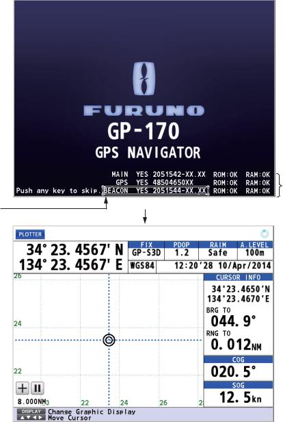
Press the  key to turn the power on. The start-up screen appears for 30 seconds then the last-used screen appears.
|
Self test |
|
Appears when |
results |
|
Start-up screen |
||
internal beacon |
||
XX: Program version numbers |
||
receiver is installed. |
|
Last-used screen (example: plotter display)
DGPS beacon receiver
The GP-170 is available in two specifications, with DGPS beacon receiver and no DGPS beacon receiver. Only the beacon receiver equipped GP-170 has DGPS capability. To get DGPS capability, install the optional internal beacon receiver (name: beacon receiver set, type: OP20-42, code no.: 000-023-637) or connect an external beacon receiver.
|
|
Status indications |
|
|
Indication |
|
|
System |
|
2D positioning |
3D positioning |
|
||
|
|
|||
GP-2D |
GP-3D |
|
GPS |
|
GP-S2D |
GP-S3D |
|
GPS + SBAS |
|
1-3
1. OPERATIONAL OVERVIEW
Indication |
System |
||
2D positioning |
3D positioning |
||
|
|||
GP-D2D |
GP-D3D |
GPS + Differential |
|
GP-D2D (Yellow) |
GP-D3D (Yellow) |
GPS + Differential (WER>10%) |
|
GP-D2D! (Yellow) |
GP-D3D! (Yellow) |
GPS + Differential (Unmonitored) |
|
GA-2D |
GA-3D |
GALILEO |
|
GA-S2D |
GA-S3D |
GALILEO + SBAS |
|
GA-D2D |
GA-D3D |
GALILEO + Differential |
|
GA-D2D (Yellow) |
GA-D3D (Yellow) |
GALILEO + Differential (WER>10%) |
|
GA-D2D! (Yellow) |
GA-D3D! (Yellow) |
GALILEO + Differential (Unmonitored) |
|
GL-2D |
GL-3D |
GLONASS |
|
GL-S2D |
GL-S3D |
GLONASS + SBAS |
|
GL-D2D |
GL-D3D |
GLONASS + Differential |
|
GL-D2D (Yellow) |
GL-D3D (Yellow) |
GLONASS + Differential (WER>10%) |
|
GL-D2D! (Yellow) |
GL-D3D! (Yellow) |
GLONASS + Differential (Unmonitored) |
|
GN-2D |
GN-3D |
Multi |
|
GN-S2D |
GN-S3D |
Multi + SBAS |
|
GN-D2D |
GN-D3D |
Multi + Differential |
|
GN-D2D (Yellow) |
GN-D3D (Yellow) |
Multi + Differential (WER>10%) |
|
GN-D2D! (Yellow) |
GN-D3D! (Yellow) |
Multi + Differential (Unmonitored) |
|
No Fix |
|
No fixed |
|
2D positioning: Three satellites are used.
3D positioning: More than four satellites are used.
Note 1: GLONASS, GALILEO and Multi are reserved for future use.
Note 2: The screen refreshes slower in low ambient temperature.
To turn the power off, press the  key.
key.
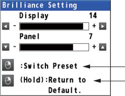
1.3How to Adjust the Brilliance of the Display and Panel
1. Press the BRILL key to show the following setting window.
Switch the color mode between day mode and night mode.
Long-press to restore the settings to default of day mode.
2.To adjust the display brilliance, use the cursorpad (W or X) or the BRILL key (setting range: 0 to 15, default: 14 for day mode/6 for night mode).
3.To adjust the panel brilliance, use the cursorpad (S or T) (setting range: 0 to 9, default: 7 for day and night modes).
4.Press the MENU/ESC key to close the setting window.
1-4

1. OPERATIONAL OVERVIEW
Note 1: The default settings for night mode is 6 for [Display] and 7 for [Panel]. If the display is difficult to see when switching to the night mode, use the cursorpad (X) to increase the display brilliance.
Note 2: Whenever the brilliance mode is changed, the last-used brilliance for the selected mode is set.
Note 3: When the brilliance is preset, the background color is also preset (see paragraph 2.1.1). So both the brilliance and the background color are restored to the
default when long-pressing the  key.
key.
1.4How to Select the Display Mode
There are five display modes: PLOTTER, INTEGRITY, HIGHWAY, COURSE and DATA. Press the DISPLAY key to select the display mode, in the following sequence. To reverse the order, long-press the DISPLAY key.
 PLOTTER
  INTEGRITY
  HIGHWAY
 : Short-press the DISPLAY key
 : Long-press the DISPLAY key
DATA  COURSE
You can turn off the highway, course or data display if its use is not required.
1.Press the MENU/ESC key to open the main menu.
2.Select [1 Display] then [9 Display Select].
3.Select [3 Highway], [4 Course] or [5 Data].
4.Select [1 On] or [2 Off]. The display modes which are set to off are skipped when operating the DISPLAY key.
Note: The plotter and integrity displays can not be disabled.
5.Press the MENU/ESC key to close the main menu.
The data is arranged according to data type.
Mode 
Common information
Main information
Guidance or alert information*
*: The alert information is displayed when an alert occurs.
1-5

1. OPERATIONAL OVERVIEW
Plotter Display
This icon appears when the number of satellites used for positioning is more than four and the high precision speed computing is available.
Ship’s  position*
North  mark
mark
Grid 
Range scale
Cursor on (Cursor mode):  Cursor off (Chart mode):
This icon appears |
Distance for RAIM reliability |
Spinner rotates when |
|||
during the |
|
HDOP: 2D |
the equipment is |
||
synchronization |
|
functioning normally. |
|||
with ECDIS. |
Status PDOP: 3D |
Time and date of |
|||
indication |
RAIM reliability |
||||
Datum |
|||||
Position FIX |
|||||
|
|
|
|
||
|
|
|
|
Cursor mode: |
|
|
|
|
|
Cursor position, |
|
|
|
|
|
Chart mode: |
|
|
|
|
|
No indication |
|
|
|
|
|
Cursor mode: |
|
|
|
|
|
Bearing from |
|
|
|
|
|
ship to cursor, |
|
|
|
|
|
Chart mode: |
|
|
|
|
|
Bearing |
|
|
|
|
|
Cursor mode: |
|
|
|
|
|
Range from |
|
|
|
|
|
ship to cursor, |
|
|
|
|
|
Chart mode: |
|
|
|
|
|
Range |
|
|
|
|
|
Course over |
|
|
|
|
|
ground |
|
|
|
Speed over |
Ship’s mark Ship’s track |
Course bar |
ground |
Heading line |
*: Shows the ship’s position adjusted with the setting position offset based on the selected datum (refer to paragraph 9.3.5).
Note: The color of the ship’s position data depends on positioning status.
Black: GPS position fix Red: No GPS position fix
Integrity Display
Satellites used for positioning (Satellite numbers used for positioning are displayed in white, or black if not used for positioning.)
Receiver signal level (Bars show signal level.)
Elevation 60° |
Elevation 30° |
Elevation 0° |
1-6
1. OPERATIONAL OVERVIEW
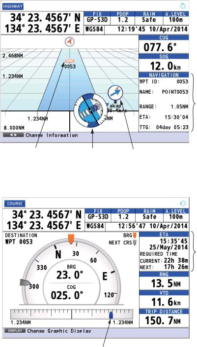
Highway Display
 Course over ground
 Speed over ground
Course information
Waypoint |
Attitude gauge |
Weather data |
Course Display
Estimated time and date of arrival
 Range
Range
 Velocity to destination
 Trip distance
Cross track distance indication
1-7

1. OPERATIONAL OVERVIEW
Data Display
Note: When invalid data is input, “- - - -” is displayed.
1.5Main Menu Overview
1. Press the MENU/ESC key to open the main menu.
 These marks indicate additional menus.
Basic operation or alert information
2.Use the cursorpad (S or T) to select a menu item then press the NU/CU ENT key. You can also select a menu item by pressing the numeric keys. This manual states this operating procedure as “Select [No. menu name].” The menu items that have a X indicate additional menus.
Second layer |
Third layer |
1-8

1. OPERATIONAL OVERVIEW
3.Select an option.
4.Press the MENU/ESC key to close the main menu.
1.6List Overview
The LIST key displays the mark list, route list and station list, in the sequence shown below.
|
Any display |
|
Mark List |
|
|
||
|
|
Station List |
|
Route List |
(Requires internal beacon receiver.) |
|
: Short-press the LIST key |
|
|
|
|
|
: Long-press the LIST key |
How to save position in a list
1.Press the MENU/ESC key to open the main menu.
2.Select [8 System Setting] then [2 Plotter].
3.Select [7 List Number].
4.Select [1 Keeping] or [2 Not Saved]. [Keeping]: Saves position in lists.
[Not Saved]: No. 0001 is always displayed at the top of the list.
5.Press the MENU/ESC key to close the main menu.
1-9

1. OPERATIONAL OVERVIEW
How to change the data to display on the mark list
1.Press the MENU/ESC key to open the main menu.
2.Select [8 System Setting] then [2 Plotter].
3.Select [8 List Information].
4.Select [1 L/L] or [2 Range/Bearing]. [L/L]: Displays latitude and longitude.
[Range/Bearing]: Displays the bearing and distance from own ship to a mark or a waypoint.
5.Press the MENU/ESC key to close the main menu.
L/L |
Range/Bearing |
1.7Context Menu Overview
You can display a context menu for track, mark, route, waypoint or MOB. For example, do the following to open the context menu for a mark.
1.Press the CURSOR ON/OFF key to turn the cursor on.
2.Use the cursorpad to select a mark then press the  key. The context menu opens.
1-10
2.PLOTTER DISPLAY OVERVIEW, TRACK
2.1How to Set the Display
2.1.1How to select the background color
You can select the background color to suit lighting conditions or environment (see section 1.3).
1.Press the MENU/ESC key to open the main menu.
2.Select [1 Display] then [1 Back Ground].
3.Select [1 White] or [2 Black].
4.Press the MENU/ESC key to close the main menu.
2.1.2How to zoom in or out the display
You can change the range scale on the plotter display. Press the ZOOM IN key to zoom in the display and the ZOOM OUT key to zoom out the display. The horizontal range is available among 0.125, 0.25, 0.5, 1, 2, 4, 8, 16, 32, 64, 128, 256, 512 and 1024 NM.
2.1.3How to change the display orientation
The display orientation for the plotter display can be selected to north-up or courseup. Press the NU/CU ENT key to change the display orientation.
North-up
True north (0°) is at the top of the display. Own ship moves on the display in accordance with true motion. The land is stationary.
2-1
2. PLOTTER DISPLAY OVERVIEW, TRACK
Course-up
When the destination is set, the destination is at the top of the display and the north mark (  ) appears at the left side of the display.
When the destination is not set, own ship's course is upward on the display at the mo-
ment you select the course-up and the north mark (  ) appears at the left side of the display.
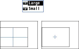
2.1.4How to turn the cursor on/off, change cursor size
Press the CURSOR ON/OFF key to turn the cursor on or off.
Cursor size
You can change the cursor size.
1.Press the MENU/ESC key to open the main menu.
2.Select [1 Display] then [6 Cursor Size].
3.Select [1 Large] or [2 Small].
Large |
Small |
4. Press the MENU/ESC key to close the main menu.
2.1.5How to move the cursor
You can move the cursor with the cursorpad.
1.Press the CURSOR ON/OFF key to turn the cursor on.
2.Press or hold down the cursorpad. The cursor moves in the direction of the arrow or diagonal. The display shifts when the cursor reaches an edge of the display, in the direction opposite of the arrow pressed on the cursorpad. When the cursor is turned on, the cursor position, the bearing and range from own ship to the cursor appear at the right side of the display (see the plotter display on page 1-6).
2.1.6How to shift the display
You can shift the display on the plotter display.
1.Press the CURSOR ON/OFF key to turn the cursor off.
2.Press or hold down the cursorpad.
2-2

2. PLOTTER DISPLAY OVERVIEW, TRACK
2.1.7How to center the cursor position or ship's position
Cursor position
1.Press the CURSOR ON/OFF key to turn the cursor on.
2.Press the CENTER key.
Ship's position
1.Press the CURSOR ON/OFF key to turn the cursor off.
2.Press the CENTER key.
Note: When own ship reaches an edge of the display, own ship’s mark is automatically centered.
2.1.8How to show or hide the grid and change its color
You can show or hide the grid and change its color (see "Plotter Display" on page 1- 6).
1.Press the MENU/ESC key to open the main menu.
2.Select [1 Display] then [2 Grid].
|
3. |
Select the grid color. To turn the grid off, select [8 Off]. When selecting [7 White/ |
|||
|
|
Black], the grid color depends on the background color. |
|||
|
|
|
|
|
|
|
|
|
Background color |
Grid color |
|
|
|
|
White |
Black |
|
|
|
|
Black |
White |
|
|
4. |
Press the |
MENU/ESC key to close the |
main menu. |
|
2.1.9 |
How to show or hide the XTL line and change its color |
||||
The XTL lines (see the illustration on page 5-1) straddle the intended course line and they mark the XTL range. You can show or hide the lines and change their color.
1.Press the MENU/ESC key to open the main menu.
2.Select [1 Display] then [3 Lines Color].
2-3

2.PLOTTER DISPLAY OVERVIEW, TRACK
3.Select [1 XTL Line].
4.Select the XTL line color. To turn the XTL line off, select [8 Off].
5.Press the MENU/ESC key to close the main menu.
2.1.10How to show or hide the heading line and change its color
You can show or hide the heading line and change its color.
1.Press the MENU/ESC key to open the main menu.
2.Select [1 Display] then [3 Lines Color].
3.Select [2 Heading Line].
4.Select the heading line color. To turn the heading line off, select [8 Off].
5.Press the MENU/ESC key to close the main menu.
2.1.11How to set the COG vector
The COG vector is a vector line that runs from own ship’s icon. This vector shows speed and course of own ship. The top of a vector shows estimated position of own ship after the selected vector time elapses.
Note: The COG vector is not displayed when there is no position data.
How to show or hide the COG vector and change its color
1.Press the MENU/ESC key to open the main menu.
2.Select [1 Display] then [3 Lines Color].
3.Select [3 Course Vector].
4.Select the COG vector color. To turn the COG vector off, select [8 Off].
5.Press the MENU/ESC key to close the main menu.
How to set the COG vector time
1.Press the MENU/ESC key to open the main menu.
2.Select [1 Display] then [3 Lines Color].
3.Select [4 Course Vector Time].
4.Select the time for the COG vector. If you select [9 Continuous], the COG vector extends to the edge of the display.
5.Press the MENU/ESC key to close the main menu.
2-4

2. PLOTTER DISPLAY OVERVIEW, TRACK
2.1.12How to display the time mark
You can display the time mark on the track every hour on the hour.
Track
 T
T
 T
T
 T
T  T
T
1.Press the MENU/ESC key to open the main menu.
2.Select [1 Display] then [4 Time Mark].
3.Select the color for the time mark. To turn the time mark off, select [8 Off].
4.Press the MENU/ESC key to close the main menu.
2.1.13How to display the names for marks and waypoints
You can display the names for marks and waypoints.
1.Press the MENU/ESC key to open the main menu.
2.Select [1 Display] then [5 Mark/WPT Name].
3.Select [1 On (All)], [2 On (WPT)] or [3 Off].
[On (All)]: Displays the names for marks and waypoints. [On (WPT)]: Displays the waypoint names.
[Off]: Turns off the names.
4.Press the MENU/ESC key to close the main menu.
2.1.14How to show or hide the weather data
You can display the direction and the speed of the wind analyzed from type 16 message when the weather data is received from a beacon station (see page 7-2).
|
|
|
|
The arrow points in wind direction |
|
|
|
|
and its length changes according |
|
|
|
|
|
akap |
akap |
to wind speed. |
||
4m/s |
4m/s |
|
||
Plotter display |
Highway display |
|
||
Note: This menu requires an internal or external beacon receiver.
1.Press the MENU/ESC key to open the main menu.
2.Select [1 Display] then [0 Data Overlay].
3.Select [1 Weather (Type16)], then [1 On] or [2 Off].
[On]: Displays the weather data (type 16 message) on the plotter display.
[Off]: Turns off the weather data (type 16 message) on the plotter display.
Note: On the highway display, the weather data is displayed regardless of on/off.
4.Press the MENU/ESC key to close the main menu.
2-5

2. PLOTTER DISPLAY OVERVIEW, TRACK
2.2Bearing Reference
Ship’s course and bearing to a waypoint are displayed in true or magnetic bearing. Magnetic bearing is true bearing plus (or minus) earth’s magnetic variation.
2.2.1How to select bearing reference
The default setting displays true bearing.
1.Press the MENU/ESC key to open the main menu.
2.Select [8 System Setting] then [2 Plotter].
3.Select [1 Bearing Reference].
4.Select [1 True] or [2 Magnetic].
[True]: Gyrocompass or satellite compass using true bearing [Magnetic]: Magnetic compass
5.Press the MENU/ESC key to close the main menu.
When selecting [2 Magnetic] at step 4, follow the steps at paragraph 2.2.2.
2.2.2How to set the magnetic variation
The location of the magnetic north pole is different from the geographical north pole. This causes a difference between the true and magnetic north direction. This difference is called magnetic variation, and varies with respect to the observation point on the earth. Magnetic variation is entered automatically or manually.
1.Press the MENU/ESC key to open the main menu.
2.Select [8 System Setting] then [2 Plotter].
3.Select [2 Magnetic Variation].
4.Select [1 Auto] or [2 Manual]. If you select [1 Auto], go to step 7. For [2 Manual], go to step 5.
5.Enter the variation with the numeric keys. To change the coordinate, select "E" then press one of keys from 0 to 9.
6.Move the cursor to [Enter] then press the NU/ CU ENT key.
7.Press the MENU/ESC key to close the main menu.
2-6

2. PLOTTER DISPLAY OVERVIEW, TRACK
2.3About Tracks
The GP-170 stores 1,000 points of track.
2.3.1How to start or stop plotting and recording of the track
Press the PLOT ON/OFF key to start or stop plotting and recording of the track. The pop-up message "Resuming Track Plot" or "Stopping Track Plot" appears at the left
side of the display for two seconds. When track plotting is stopped, the  icon appears at the bottom left corner of the display.
2.3.2How to set the track plotting interval
In drawing the track, the position of your ship is stored into the memory of this equipment at an interval of time or distance. A shorter interval provides better reconstruction of the track, but the storage time of the track is reduced. When the track memory becomes full, the oldest track is erased to make room for the latest.
1.Press the MENU/ESC key to open the main menu.
2.Select [2 Track/Mark] then [1 Track REC].
3.Select [1 Time] or [2 Distance].
[Time]: Enter the time interval with the numeric keys (setting range: 0001 (1 sec) to 6000 (60 min)).
[Distance]: Enter the distance interval with the numeric keys (setting range: 00.01 to 99.99 NM).
Time |
Distance |
4.Move the cursor to [Enter] then press the NU/CU ENT key.
5.Press the MENU/ESC key to close the main menu.
2-7

2. PLOTTER DISPLAY OVERVIEW, TRACK
2.3.3How to set the track color
You can select the track color as follows:
1.Press the MENU/ESC key to open the main menu.
2.Select [2 Track/Mark] then [2 Track Color].
3.Select the track color.
4.Press the MENU/ESC key to close the main menu.
How to change the color of selected track
1.Put the cursor on the track.
2.Press the  key to open the context menu.
3.Select [1 Change Color].
4.Select the color to change.
5.Press the MENU/ESC key to close the context menu.
2.3.4How to erase the track
How to erase all tracks from the main menu
1.Press the MENU/ESC key to open the main menu.
2.Select [2 Track/Mark] then [9 Erase Track].
3.Select [1 Erase Track]. The confirmation message appears.
4.Select [1 Yes].
5.Press the MENU/ESC key to close the main menu.
How to erase all tracks from the context menu
1.Put the cursor on a track.
2.Press the  key to open the context menu.
3.Select [2 Erase All]. The confirmation message appears.
4.Select [1 Yes].
2-8

3.MARKS
You can put marks on the plotter display to indicate good fishing spot, location of traps, etc. Marks have 16 shapes and seven colors. Also, marks can be connected with lines.
3.1How to Enter a Mark on the Plotter Display
3.1.1How to preset mark appearance
Set the default mark shape, color, line type to use when entering a mark.
Mark shape
You can select a mark shape from 16 types.
1.Press the MENU/ESC key to open the main menu.
2.Select [2 Track/Mark] then [3 Mark Shape].
3.Use the cursorpad to select the shape then press the NU/CU ENT key.
4.Press the MENU/ESC key to close the main menu.
Mark color
You can select a mark color from seven colors.
1.Press the MENU/ESC key to open the main menu.
2.Select [2 Track/Mark] then [4 Mark Color].
3.Select the color.
4.Press the MENU/ESC key to close the main menu.
Mark line
Marks can be connected with lines, and three types of lines are available.
1. Press the MENU/ESC key to open the main menu.
3-1

3. MARKS
2.Select [2 Track/Mark] then [5 Mark Line].
3.Select the line type.
• |
[None]: None |
• |
[Solid]: |
|
|
||||
• |
[Dash]: |
• |
[Alternate Dash]: |
|
4. Press the MENU/ESC key to close the main menu.
When continuously entering marks by the method described in paragraph 3.1.2, the marks are connected with the selected line.
Mark line color
You can select a mark line color from seven colors.
1.Press the MENU/ESC key to open the main menu.
2.Select [2 Track/Mark] then [6 Line Color].
3.Select the color.
4.Press the MENU/ESC key to close the main menu.
3.1.2How to enter a mark at the cursor position
1.Press the CURSOR ON/OFF key to turn the cursor on.
2.Use the cursorpad to place the cursor on the location for a mark.
3.Press the MARK EVENT key to put the mark. This mark is named with the youngest unused mark number (for example, "POINT0001"), and saved to the mark list.
3.1.3How to enter a mark from the mark list
At the cursor position
1.Press the MENU/ESC key to open the main menu.
2.Select [3 Navigation] then [1 Mark Registration].
3-2
 Loading...