


Back

9-52 Ashihara-cho,
Nishinomiya, Japan
Telephone : 0798-65-2111
fax |
: 0798-65-4200 |
All rights reserved. |
Printed in Japan |
PUB.No. OME-23520
( TENI ) FCV-292
Your Local Agent/Dealer
FIRST EDITION : OCT. 1994 L1 : DEC. 24,2003
*00080637800*
*00080637800*
* 0 0 0 8 0 6 3 7 8 0 0 *
*OME23520L10*
*OME23520L10*
* O M E 2 3 5 2 0 L 1 0 *


SAFETY INFORMATION FOR THE OPERATOR
 WARNING
Do not open the cover of the equipment.
This equipment uses high voltage electricity which can shock, burn, or cause death.
Only qualified personnel should work inside the equipment.
Do not dissasemble or modify the equipment.
Fire, electrical shock or serious injury can result.
Immediately turn off the power at the ship's mains switchboard if water or foreign object falls into the equipment or the equipment is emitting smoke or fire.
Continued use of the equipment can cause fire, electrical shock or serious injury.
 CAUTION
Do not place liquid-filled containers on the top of the equipment.
Fire or electrical shock can result if a liquid spills into the equipment.
Do not place heater near the equipment.
Heat can melt the power cord, which can result in fire or electrical shock.
Do not operate the unit with wet hands.
Electrical shock can result.
Use the correct fuse.
Use of the wrong fuse can cause fire or equipment damage.
(Continued on next page)
ii


SAFETY INFORMATION FOR THE INSTALLER
 WARNING
Only qualified personnel should work inside the equipment.
This equipment uses high voltage electricity which can shock, burn, or cause death.
Turn off the power at the ship's mains switchboard before beginning the installation. Post a warning sign near the switchboard to ensure that the power will not be applied while the equipment is being installed.
Serious injury or death can result if the power is not turned off, or is applied while the equipment is being installed.
 CAUTION
Ground the equipment to prevent electrical shock and mutual interference.
Ungrounded equipment can give off or receive electro-magnetic interference or cause electrical shock.
Confirm that the power supply voltage is compatible with the voltage rating of the equipment.
Connection to the wrong power supply can cause fire or equipment damage. The voltage rating appears on the label at the rear of the equipment.
NOTICE
The mounting location must satisfy the following conditions:
Away from rain and water splash Out of direct sunlight
Away from air conditioner vents
Away from magnets and magnetic fields Moderate and stable in temperature and humidity
iv


Table of Contents
A Word To Furuno FCV-292 Owners:.................................................................. |
i |
Features ................................................................................................................................ |
i |
1.HANDLING PRECAUTION ................................................................................ |
1 |
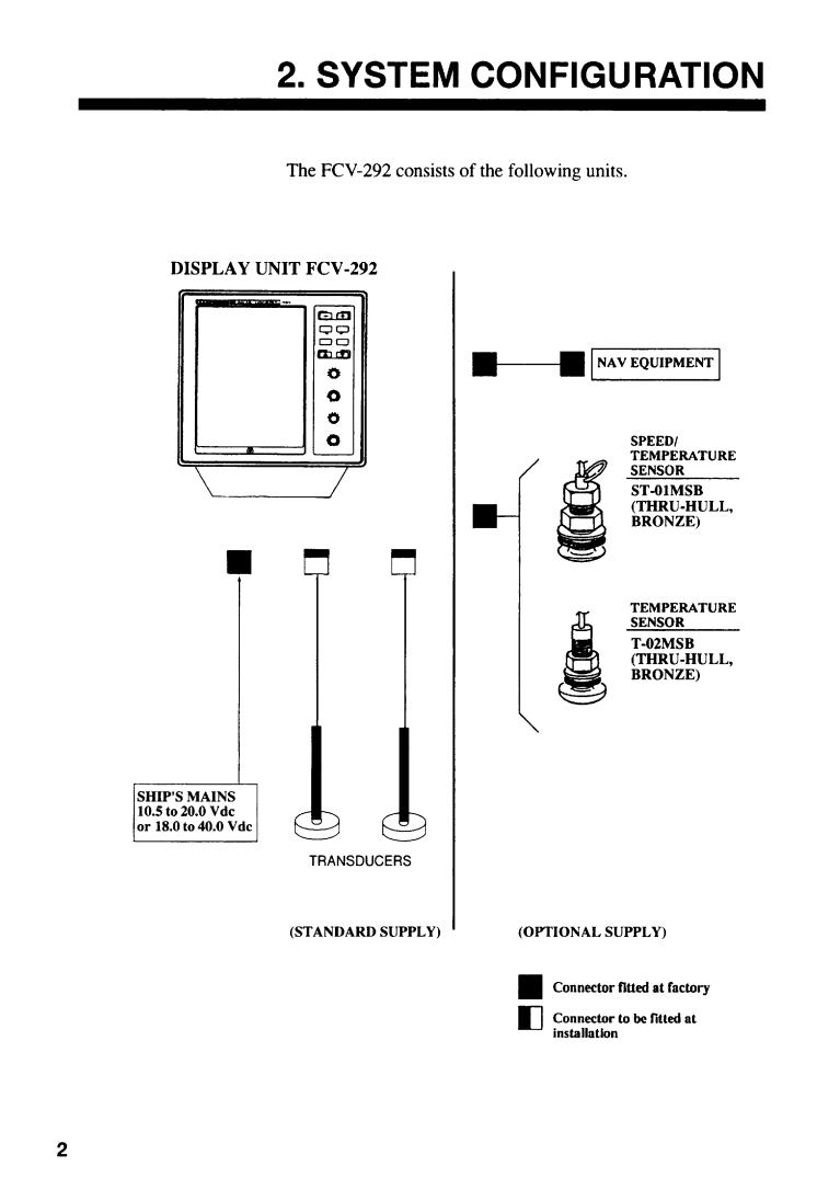
2.SYSTEM CONFIGURATION.............................................................................. |
2 |
3.PRINCIPLE OF OPERATION ............................................................................ |
3 |
4.OPERATING CONTROLS ................................................................................. |
4 |
5.BASIC OPERATION .......................................................................................... |
6 |
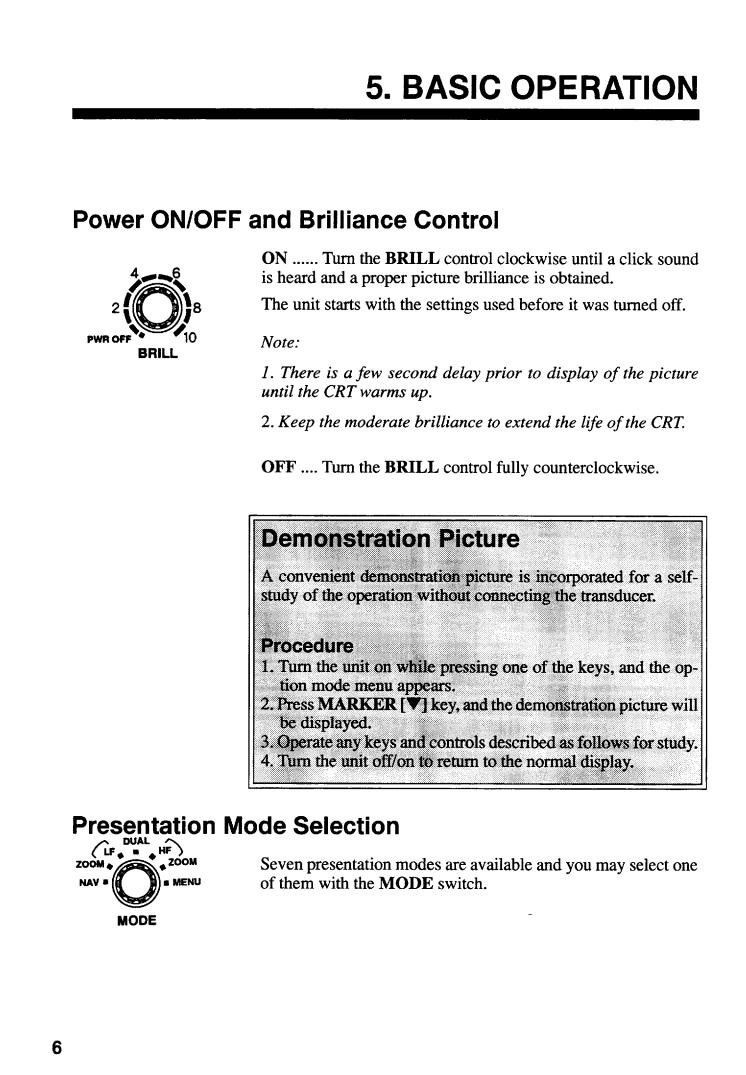
Power ON/OFF and Brilliance Control................................................................................... |
6 |
Demonstration Picture........................................................................................................... |
6 |
Presentation Mode Selection ................................................................................................ |
6 |
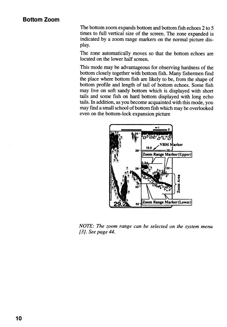
Zoom Picture Selection......................................................................................................... |
9 |
Automatic Operation ........................................................................................................... |
12 |
Manual Operation ............................................................................................................... |
12 |
Picture Advance Speed Selection ....................................................................................... |
14 |
Eliminating Low Intensity Echoes........................................................................................ |
15 |
Turning on A-Scope Presentation ....................................................................................... |
15 |
Measuring Depth to Fish School ......................................................................................... |
15 |
6.FISH AND BOTTOM ALARMS........................................................................ |
16 |
7.ADJUSTING PICTURE BY MENU .................................................................. |
18 |
Eliminating Interference (NOISE LIMITER) ......................................................................... |
18 |
Eliminating Low Level Noise (CLUTTER LEVEL)................................................................ |
19 |
Adjusting Preset Gain ......................................................................................................... |
19 |
Selecting Background Color and Echo Color (HUE SELECTION)....................................... |
20 |
8.DISPLAYS ........................................................................................................ |
21 |
Video Sounder Picture ........................................................................................................ |
21 |
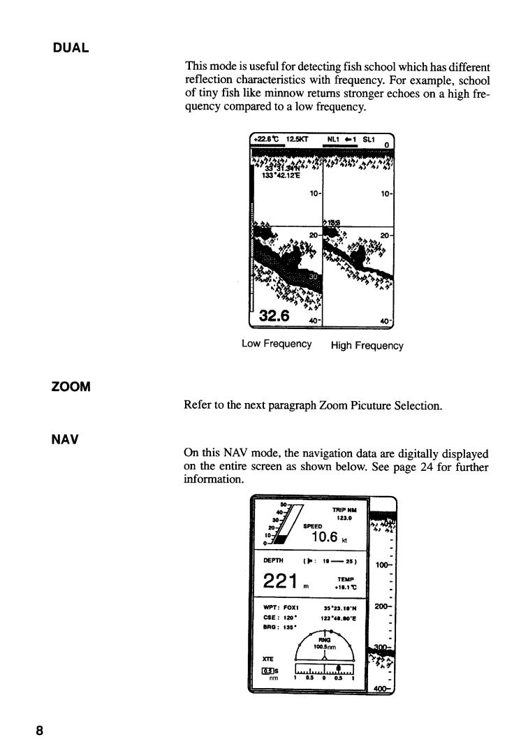
Navigation Data .................................................................................................................. |
24 |
9.INTERPRETING THE DISPLAY ...................................................................... |
25 |
Frequency........................................................................................................................... |
25 |
Detecting Area .................................................................................................................... |
25 |
Zero Line ............................................................................................................................ |
26 |
Fish School Echoes ............................................................................................................ |
27 |
Bottom Echo ....................................................................................................................... |
27 |
Surface Noise/Aeration ....................................................................................................... |
28 |
vii
10.MAINTENANCE ............................................................................................. |
29 |
Fuse Replacement .............................................................................................................. |
29 |
Cleaning.............................................................................................................................. |
29 |
Maintenance of Transducer ................................................................................................. |
30 |
11.TROUBLESHOOTING ................................................................................... |
31 |
Basic Troubleshooting ......................................................................................................... |
31 |
Diagnostic Self-Check ......................................................................................................... |
33 |
Transducer Check ............................................................................................................... |
34 |
Speed/Temperature Sensor (Option) Check ........................................................................ |
34 |
12.INSTALLATION.............................................................................................. |
35 |
Display Unit Installation ....................................................................................................... |
35 |
Transducer Installation ........................................................................................................ |
37 |
Transducer Preparation and Painting .................................................................................. |
37 |
Speed/Temperature Sensor................................................................................................. |
38 |
Cable Connections .............................................................................................................. |
39 |
13.SYSTEM MENU SETTING............................................................................. |
41 |
Operation Procedure ........................................................................................................... |
41 |
Description of System Menu Item........................................................................................ |
42 |
Restoring Factory Settings .................................................................................................. |
44 |
14.SPECIFICATIONS.......................................................................................... |
45 |
Complete Set....................................................................................................................... |
47 |
Installation Materials............................................................................................................ |
48 |
Accessories......................................................................................................................... |
48 |
Spare Parts ......................................................................................................................... |
48 |
Option.................................................................................................................................. |
48 |
Transducer & Hull Bottom Installation Materials................................................................... |
49 |
APPENDIX |
|
1. Changing Transducer Output Power Setting ....................................................................... |
A-1 |
2. Changing Transducer Frequency Specifications ................................................................. |
A-2 |
3. Adjustment After Replacement of MAIN or AMP Board (entering amplifier |
|
gain offset) .......................................................................................................................... |
A-4 |
4. Transducer 50BL-12/50BL-24H........................................................................................... |
A-6 |
5. New BLT Transducers......................................................................................................... |
A-7 |
OUTLINE DRAWING ................................................................................ |
D-1 |
INTERCONNECTION DIAGRAM ........................................................................... |
S-1 |
viii


 Loading...