


 Loading...
OPERATOR'S MANUAL
MULTI-COLOR LCD RADAR
FR-8045
FR-8065
FR-8125
Model FR-8255
PRODUCT NAME: MARINE RADAR
www.furuno.com

The paper used in this manual is elemental chlorine free.
FURUNO Authorized Distributor/Dealer
9-52 Ashihara-cho,
Nishinomiya, 662-8580, JAPAN
All rights reserved. |
Printed in Japan |
A : JAN . 2014
A5 : AUG . 22, 2014
Pub. No. OME-36320-A5
(AKMU ) FR-8045/8065/8125
0 0 0 1 7 8 5 0 2 1 0

IMPORTANT NOTICES
General
•This manual has been authored with simplified grammar, to meet the needs of international users.
•The operator of this equipment must read and follow the descriptions in this manual. Wrong operation or maintenance can cancel the warranty or cause injury.
•Do not copy any part of this manual without written permission from FURUNO.
•If this manual is lost or worn, contact your dealer about replacement.
•The contents of this manual and equipment specifications can change without notice.
•The example screens (or illustrations) shown in this manual can be different from the screens you see on your display. The screens you see depend on your system configuration and equipment settings.
•Save this manual for future reference.
•Any modification of the equipment (including software) by persons not authorized by FURUNO will cancel the warranty.
•All brand and product names are trademarks, registered trademarks or service marks of their respective holders.
•Ricoh bitmap font is a trademark or registered trademark of Ricoh Company, Ltd.
How to discard this product
Discard this product according to local regulations for the disposal of industrial waste. For disposal in the USA, see the homepage of the Electronics Industries Alliance (http://www.eiae.org/) for the correct method of disposal.
How to discard a used battery
Some FURUNO products have a battery(ies). To see if your product has a battery, see the chapter on Maintenance. Follow the instructions below if a battery is used. Tape the + and - terminals of battery before disposal to prevent fire, heat generation caused by short circuit.
In the European Union
The crossed-out trash can symbol indicates that all types of batteries |
|
|
must not be discarded in standard trash, or at a trash site. Take the |
|
|
used batteries to a battery collection site according to your national |
Cd |
|
legislation and the Batteries Directive 2006/66/EU. |
||
|
In the USA
The Mobius loop symbol (three chasing arrows) indicates that Ni-Cd and lead-acid rechargeable batteries must be recycled. Take the used
batteries to a battery collection site according to local laws.
Ni-Cd Pb
In the other countries
There are no international standards for the battery recycle symbol. The number of symbols can increase when the other countries make their own recycle symbols in the future.
i

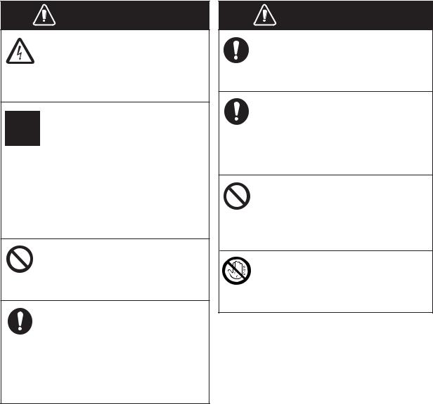
SAFETY INSTRUCTIONS
Read these safety instructions before you operate the equipment.
WARNING |
Indicates a condition that can cause death or serious |
|
injury if not avoided. |
|
|
|
|
|
CAUTION |
Indicates a condition that can cause minor or moderate |
|
injury if not avoided. |
|
|
Warning, Caution |
Prohibitive Action |
Mandatory Action |
 WARNING
Model |
100W/m2 |
10W/m2 |
||
|
|
|
|
|
FR-8045 |
XN-12A |
N/A |
1.1m |
|
XN-13A |
N/A |
1.0m |
||
|
||||
|
|
|
|
|
FR-8065 |
XN-12A |
N/A |
1.9m |
|
|
|
|
||
XN-13A |
N/A |
1.7m |
||
|
||||
|
|
|
|
|
FR-8125 |
XN-12A |
N/A |
2.1m |
|
|
|
|
||
XN-13A |
N/A |
1.9m |
||
|
||||
|
|
|
|
|
FR-8255 |
XN-12A |
0.6m |
4.6m |
|
|
|
|
||
XN-13A |
0.4m |
3.1m |
||
|
||||
|
|
|
|
|
ii
WARNING
ELECTRICAL SHOCK HAZARD
Do not open the equipment.
Only qualified persons can work inside the equipment.
Turn off the power before you service the antenna unit. Post a warning sign near the power switch not to turn on the power while you service the antenna unit.
Prevent the potential risk of being struck by the rotating antenna and exposure to RF radiation hazard.
Do not disassemble or modify the equipment.
Fire or electrical shock can occur.
Turn off the power immediately if water leaks into the equipment or smoke or fire is coming
from the equipment.
Failure to turn off the equipment can cause fire or electrical shock.
SAFETY INSTRUCTIONS
WARNING
Use the correct fuse.
A wrong fuse can damage the equipment and cause fire.
Keep heater away from the equipment.
Heat can change the equipment shape and melt the power cord, which can cause fire or electrical shock.
Do not put liquid-filled containers on the top of the equipment.
Fire or electrical shock can occur if a liquid spills into the equipment.
Do not operate the equipment with wet hands.
Electrical shock can occur.
iii
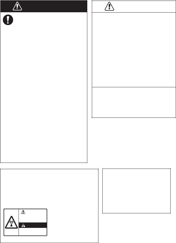
SAFETY INSTRUCTIONS
WARNING
Do not depend on one navigation device for the navigation of the ship. The navigator must check all aids available to confirm position. Electronic aids are not a replacement for basic navigation principles and common sense.
·The ARPA automatically tracks an automatically or manually acquired radar target and calculates its course and speed, indicating them by a vector. Since the data from the auto plotter depend on the selected radar targets, the radar must be optimally tuned for use with the auto plotter, to ensure required targets will not be lost or unnecessary targets like sea returns and noise will not be acquired and tracked.
·A target is not always a landmass, reef, ship, but can also be returns from the sea surface and from clutter. As the level of clutter changes with the environment, the operator must correctly adjust the
A/C SEA, A/C RAIN and GAIN controls so that the target echoes do not disappear from the radar screen.
CAUTION
The tracking accuracy is affected by the following:
·The tracking accuracy is affected by course change. One to two minutes is required to restore vectors to full accuracy after a sudden course change. (The actual amount depends on gyrocompass specifications.)
·The amount of tracking delay is inversely proportional to the relative speed of the target. Delay is on the order of 15-30 seconds for high relative speed; 30-60 seconds for low relative speed.
The data from ARPA and AIS are intended for reference purposes only.
Check all available navigation aids to determine target movement.
WARNING LABELS
Warning labels are attached to the equipment. Do not remove any label. If a label is missing or damaged, contact a FURUNO agent or dealer about replacement.
|
ANTENNA UNIT |
||
WARNING |
|||
Name: |
Warning Sticker |
||
Radiation hazard. Only qualified |
|||
personnel should work inside scanner. |
Type: |
03-142-3201-0 |
|
opening scanner. |
|||
Confirm that TX has stopped before |
|
|
|
Code No.: 100-266-890-10
TFT LCD
The high quality TFT (Thin Film Transistor) LCD displays 99.999% of its picture elements.
The remaining 0.001% may drop out or light, however this is an inherent property of the LCD; it is not a sign of malfunction.
iv
TABLE OF CONTENTS
|
|
|
|
...................................................................................................................FOREWORD |
|
ix |
|
SYSTEM CONFIGURATION .......................................................................................... |
xi |
||
1. OPERATION .......................................................................................................... |
1-1 |
||
1.1 |
Controls ...................................................................................................................... |
1-1 |
|
1.2 |
How to Turn the Radar On/Off and Transmit.............................................................. |
1-2 |
|
1.3 |
Display Indications...................................................................................................... |
1-3 |
|
1.4 |
How to Adjust Display Brilliance, Panel Dimmer ........................................................ |
1-4 |
|
1.5 |
Menu Description........................................................................................................ |
1-4 |
|
1.6 |
Tuning......................................................................................................................... |
|
1-6 |
1.7 |
Display Modes ............................................................................................................ |
1-7 |
|
|
1.7.1 |
How to select the display mode...................................................................... |
1-7 |
|
1.7.2 |
Description of display modes ......................................................................... |
1-8 |
1.8 |
How to Select a Range Scale................................................................................... |
1-10 |
|
1.9 |
How to Adjust the Gain (sensitivity).......................................................................... |
1-10 |
|
1.10 |
How to Reduce the Sea Clutter ................................................................................ |
1-11 |
|
1.11 |
How to Reduce the Rain Clutter ............................................................................... |
1-12 |
|
1.12 |
Automatic Adjustments of Sea and Rain Clutters..................................................... |
1-13 |
|
1.13 |
Cursor....................................................................................................................... |
|
1-14 |
1.14 |
Interference Rejector................................................................................................ |
1-15 |
|
1.15 |
How to Measure the Range to a Target ................................................................... |
1-16 |
|
|
1.15.1 |
How to adjust range ring brilliance ............................................................... |
1-16 |
|
1.15.2 |
How to measure the range with a VRM........................................................ |
1-17 |
|
1.15.3 |
How to select VRM unit ................................................................................ |
1-17 |
1.16 |
How to Measure the Bearing to a Target.................................................................. |
1-18 |
|
|
1.16.1 |
How to measure the bearing with an EBL .................................................... |
1-18 |
|
1.16.2 |
EBL reference .............................................................................................. |
1-19 |
1.17 |
How to Measure the Range and Bearing Between Two Targets ............................. |
1-19 |
|
1.18 |
How to Select a Pulselength..................................................................................... |
1-20 |
|
1.19 |
Target Alarm............................................................................................................. |
1-21 |
|
|
1.19.1 |
How to set a target alarm zone .................................................................... |
1-21 |
|
1.19.2 |
How to stop the audio alarm......................................................................... |
1-22 |
|
1.19.3 |
How to select the alarm type ........................................................................ |
1-22 |
|
1.19.4 |
How to sleep a target alarm temporarily....................................................... |
1-23 |
|
1.19.5 |
How to deactivate a target alarm.................................................................. |
1-23 |
|
1.19.6 |
How to select the target strength which triggers a target alarm ................... |
1-23 |
|
1.19.7 |
How to turn the buzzer on/off ....................................................................... |
1-23 |
1.20 |
How to Off-center the Display................................................................................... |
1-24 |
|
|
1.20.1 |
How to select the off-center mode................................................................ |
1-24 |
|
1.20.2 |
Off-center the display ................................................................................... |
1-24 |
1.21 |
Zoom ........................................................................................................................ |
|
1-26 |
|
1.21.1 |
Zoom mode .................................................................................................. |
1-26 |
|
1.21.2 |
How to zoom ................................................................................................ |
1-26 |
1.22 |
Echo Stretch............................................................................................................. |
1-28 |
|
1.23 |
Echo Average........................................................................................................... |
1-28 |
|
1.24 |
Target Trails ............................................................................................................. |
1-29 |
|
|
1.24.1 |
Trail time....................................................................................................... |
1-29 |
|
1.24.2 |
How to start, stop the trails........................................................................... |
1-30 |
|
1.24.3 |
Trail mode .................................................................................................... |
1-30 |
|
1.24.4 |
Trail gradation .............................................................................................. |
1-31 |
|
1.24.5 |
Trail color...................................................................................................... |
1-31 |
|
1.24.6 |
Trail level ...................................................................................................... |
1-32 |
v
TABLE OF CONTENTS |
|
||
|
1.24.7 |
How to restart, stop the trails ....................................................................... |
1-32 |
|
1.24.8 |
Narrow trails ................................................................................................. |
1-33 |
|
1.24.9 |
Your ship trail ............................................................................................... |
1-33 |
1.25 |
How to Send the Target Position and Enter the Origin Mark ................................... |
1-33 |
|
1.26 |
How to Hide the Heading Line Temporarily ............................................................. |
1-34 |
|
1.27 |
Presentation Brilliance ............................................................................................. |
1-34 |
|
1.28 |
Custom Setup .......................................................................................................... |
1-34 |
|
|
1.28.1 |
About custom setup ..................................................................................... |
1-34 |
|
1.28.2 |
Description of custom setup items ............................................................... |
1-35 |
|
1.28.3 |
How to set custom setups ............................................................................ |
1-36 |
1.29 |
How to Program Function Keys (F1, F2 and F3 keys) ............................................. |
1-37 |
|
1.30 |
Noise Rejector.......................................................................................................... |
1-38 |
|
1.31 |
Wiper........................................................................................................................ |
|
1-38 |
1.32 |
How to Reduce Second-trace Echoes ..................................................................... |
1-39 |
|
1.33 |
Watchman ................................................................................................................ |
1-39 |
|
1.34 |
Color Selections ....................................................................................................... |
1-40 |
|
|
1.34.1 |
Preset colors ................................................................................................ |
1-40 |
|
1.34.2 |
Custom colors .............................................................................................. |
1-41 |
1.35 |
Navigation Data........................................................................................................ |
1-42 |
|
|
1.35.1 |
Navigation data during standby.................................................................... |
1-42 |
|
1.35.2 |
Navigation data at the bottom of the screen ................................................ |
1-42 |
1.36 |
Dynamic Range........................................................................................................ |
1-43 |
|
1.37 |
Characteristics Curve............................................................................................... |
1-44 |
|
1.38 |
Waypoint Marker ...................................................................................................... |
1-45 |
|
1.39 |
Alarm Message ........................................................................................................ |
1-45 |
|
1.40 |
Echo Area ................................................................................................................ |
1-47 |
|
1.41 |
Initial Sub Menu ....................................................................................................... |
1-48 |
|
|
1.41.1 |
How to open the Initial sub menu................................................................. |
1-48 |
|
1.41.2 |
Description of Initial sub menu..................................................................... |
1-48 |
1.42 |
Units Sub Menu........................................................................................................ |
1-50 |
|
1.43 |
Sector Blank............................................................................................................. |
1-51 |
|
1.44 |
Other Menu Items .................................................................................................... |
1-52 |
|
|
1.44.1 |
Menu items on the [Brill/Color] menu........................................................... |
1-52 |
|
1.44.2 |
Menu items on the [Display] menu............................................................... |
1-53 |
|
1.44.3 |
Menu items on the [Echo] menu .................................................................. |
1-53 |
1.45 |
Remote Display........................................................................................................ |
1-54 |
|
2. DESCRIPTION OF RADAR ................................................................................... |
2-1 |
||
2.1 |
General ...................................................................................................................... |
2-1 |
|
|
2.1.1 |
Minimum and maximum ranges ..................................................................... |
2-1 |
|
2.1.2 |
Radar resolution............................................................................................. |
2-2 |
|
2.1.3 |
Bearing accuracy ........................................................................................... |
2-3 |
|
2.1.4 |
Range measurement...................................................................................... |
2-3 |
2.2 |
False Echoes ............................................................................................................. |
2-3 |
|
|
2.2.1 |
Multiple echoes .............................................................................................. |
2-3 |
|
2.2.2 |
Sidelobe echoes............................................................................................. |
2-4 |
|
2.2.3 |
Virtual image .................................................................................................. |
2-4 |
|
2.2.4 |
Shadow sector ............................................................................................... |
2-5 |
2.3 |
SART (Search and Rescue Transponder) ................................................................. |
2-5 |
|
|
2.3.1 |
SART description ........................................................................................... |
2-5 |
|
2.3.2 |
General remarks on receiving SART ............................................................. |
2-6 |
2.4 |
RACON ...................................................................................................................... |
2-6 |
|
vi
|
|
|
|
TABLE OF CONTENTS |
3. |
ARPA OPERATION............................................................................................... |
3-1 |
||
|
3.1 |
Precautions for Use.................................................................................................... |
3-1 |
|
|
3.2 |
Controls for Use with ARPA ....................................................................................... |
3-1 |
|
|
3.3 |
ARPA Display On/Off ................................................................................................. |
3-2 |
|
|
3.4 |
How to Acquire and Track the Targets ....................................................................... |
3-2 |
|
|
|
3.4.1 |
Manual acquisition .......................................................................................... |
3-2 |
|
|
3.4.2 |
Automatic acquisition ..................................................................................... |
3-3 |
|
3.5 |
How to Stop the Tracking of ARPA Target ................................................................. |
3-3 |
|
|
|
3.5.1 How to stop the tracking of selected targets .................................................. |
3-3 |
|
|
|
3.5.2 How to stop the tracking of all targets ............................................................ |
3-3 |
|
|
3.6 |
Vector Attributes ......................................................................................................... |
3-4 |
|
|
|
3.6.1 What is a vector?............................................................................................ |
3-4 |
|
|
|
3.6.2 Vector time and vector reference ................................................................... |
3-4 |
|
|
|
3.6.3 Vector of your ship ......................................................................................... |
3-5 |
|
|
3.7 |
History Display (target past position).......................................................................... |
3-6 |
|
|
3.8 |
ARPA Target Data...................................................................................................... |
3-7 |
|
|
3.9 |
CPA/TCPA Alarm ....................................................................................................... |
3-8 |
|
|
3.10 |
Proximity Alarm .......................................................................................................... |
3-9 |
|
|
3.11 |
Lost Target ................................................................................................................. |
3-9 |
|
|
3.12 |
Symbol Color............................................................................................................ |
3-10 |
|
4. |
AIS OPERATION ................................................................................................... |
4-1 |
||
|
4.1 |
Controls for Use with AIS ........................................................................................... |
4-1 |
|
|
4.2 |
AIS Display On/Off ..................................................................................................... |
4-1 |
|
|
4.3 |
AIS Symbols............................................................................................................... |
4-2 |
|
|
4.4 |
Activating, Sleeping Targets....................................................................................... |
4-2 |
|
|
4.5 |
AIS Target Data.......................................................................................................... |
4-3 |
|
|
4.6 |
How to Sort Targets.................................................................................................... |
4-4 |
|
|
4.7 |
Display Range ............................................................................................................ |
4-4 |
|
|
4.8 |
How to Display the Targets within a Specific Sector .................................................. |
4-5 |
|
|
4.9 |
Number of Targets to Display..................................................................................... |
4-5 |
|
|
4.10 |
Vector Attributes ......................................................................................................... |
4-6 |
|
|
|
4.10.1 |
What is a vector? ............................................................................................ |
4-6 |
|
|
4.10.2 |
Vector time and vector reference ................................................................... |
4-6 |
|
4.11 |
History Display (target past position).......................................................................... |
4-7 |
|
|
4.12 |
CPA/TCPA Alarm ....................................................................................................... |
4-8 |
|
|
4.13 |
Proximity Alarm .......................................................................................................... |
4-9 |
|
|
4.14 |
Lost Target ................................................................................................................. |
4-9 |
|
|
4.15 |
Symbol Color............................................................................................................ |
4-10 |
|
|
4.16 |
How to Ignore Slow Targets ..................................................................................... |
4-10 |
|
5. |
GPS OPERATION ................................................................................................. |
5-1 |
||
|
5.1 |
Navigator Mode .......................................................................................................... |
5-1 |
|
|
5.2 |
Datum |
......................................................................................................................... |
5-1 |
|
5.3 |
WAAS Setup............................................................................................................... |
5-2 |
|
|
5.4 |
Satellite Monitor.......................................................................................................... |
5-3 |
|
|
5.5 |
Cold Start.................................................................................................................... |
5-4 |
|
vii
TABLE OF CONTENTS
6. MAINTENANCE, TROUBLESHOOTING |
...............................................................6-1 |
|
6.1 |
Preventative Maintenance.......................................................................................... |
6-2 |
6.2 |
Fuse Replacement ..................................................................................................... |
6-2 |
6.3 |
Magnetron Life ........................................................................................................... |
6-3 |
6.4 |
LCD Backlight Life...................................................................................................... |
6-3 |
6.5 |
Simple Troubleshooting ............................................................................................. |
6-4 |
6.6 |
Advanced-level Troubleshooting................................................................................ |
6-5 |
6.7 |
Diagnostic Test .......................................................................................................... |
6-6 |
6.8 |
LCD Test .................................................................................................................... |
6-8 |
6.9 |
ARPA Test ................................................................................................................. |
6-9 |
6.10 |
GPS Test.................................................................................................................. |
6-10 |
APPENDIX 1 MENU TREE ....................................................................................... |
AP-1 |
|
APPENDIX 2 GEODETIC CHART LIST ................................................................... |
AP-5 |
|
SPECIFICATIONS ..................................................................................................... |
SP-1 |
|
INDEX.......................................................................................................................... |
|
IN-1 |
Declaration of Conformity |
|
|
viii

FOREWORD
A word to the Owner of the FR-8045/FR-8065/FR-8125/FR-8255 Multicolor LCD Radar.
Congratulations on your choice of the FURUNO FR-8045/FR-8065/FR-8125/FR-8255 Multi-color LCD Radar. We are confident you will see why the FURUNO name has become synonymous with quality and reliability.
Since 1948, FURUNO Electric Company has enjoyed an enviable reputation for innovative and dependable marine electronics equipment. This dedication to excellence is furthered by our extensive global network of agents and dealers.
This equipment is designed and constructed to meet the rigorous demands of the marine environment. However, no machine can perform its intended function unless installed, operated and maintained properly. Please carefully read and follow the recommended procedures for operation and maintenance.
We would appreciate feedback from you, the end-user, about whether we are achieving our purposes.
Thank you for considering and purchasing FURUNO equipment.
Features
The FR-8045/FR-8065/FR-8125/FR-8255 series displays ships, land masses, etc. on a LCD screen. This equipment can be operated using the keys, knob controls or the Cursorpad.
The main features are listed below.
•Bright 12.1-inch LCD, visible in direct sunlight.
•Easy to understand user interface with on-screen menus.
•Full-screen Echo area display provides a wider range around the vessel.
•User-programmable function keys.
•Optional Auto Plotter ARP-11 is available for ARPA operation.
•AIS data can be displayed with the connection of a FURUNO AIS Transponder/Receiver.
•Echoes can be displayed multiple colors.
Note: The Chinese font used in this equipment is Ricoh Company Ltd.’s Ricoh bitmap font.
ix
FOREWORD
Radar Type and Function Availability
This radar series is available in four types: [River], [Sea], [IEC] and [Russian-River], and function availability depends on type. The table below shows type and function availability.
[River]: For river, [Sea]: For sea, [IEC]: IEC compliant radar, [Russian-River]: For Russian river
Type and function availability
Item |
|
|
Type |
|
||
|
|
River |
Sea |
IEC |
|
Russian-River |
Automatic menu |
Menu does not close automatically. |
Menu closes automatically when |
||||
closure |
|
|
|
there is no menu operation for 10 |
||
|
|
|
|
seconds. |
|
|
Effective radius |
300 dots |
|
262 dots |
|
||
dot count |
|
|
|
|
|
|
Echo color |
Select the echo display color among |
Select the echo display color among |
||||
|
[Yellow], [Green], [Orange] or [Multi]. |
[Yellow], [Green] or [Orange]. |
||||
Echo color cus- |
Can customize the echo display col- |
Can not customize the echo display |
||||
tomizing |
or. |
|
color. |
|
||
Echo area |
Select the display area from [Normal] |
Can not select. Display area is circle |
||||
|
or [Full Screen]. |
|
only. |
|
||
Base text display |
Can show or hide the base text indi- |
Can not hide the base text indica- |
||||
|
cations. |
|
tions. |
|
||
Range preset |
Select the radar ranges to use. |
|
Can not select |
|||
|
|
|
|
|
the radar ranges |
|
|
|
|
|
|
to use. |
|
Unit defaults 1) |
1) KM 2) km/h, |
1) NM 2) kn |
|
1) KM 2) km/h, |
||
range 2) speed |
m/s |
|
|
m/s |
||
Bearing scale |
Graduation every |
1°, 5°, 10°, 30°, no |
Graduation every |
1°, 5°, 10°, 30°, nu- |
||
|
numeric indication, displayed in the |
meric indication every 30°, displayed |
||||
|
effective radius |
|
out of the effective radius |
|||
VRM unit |
Can set the VRM unit independently |
Can not set the VRM unit indepen- |
||||
|
from the range unit. |
dently from the range unit. |
||||
Range unit |
Can change the range unit when |
Can not change the range unit in |
||||
|
transmitting. |
|
transmit. Only in standby. |
|||
AIS symbol color |
Select the AIS symbol color from |
Select the AIS symbol color from |
||||
|
[Green], [Red], [Blue], [White] or |
[Green], [Blue], [White] or [Black]. |
||||
|
[Black]. |
|
|
|
|
|
Vector reference |
Select the display mode for the vector |
[True] |
|
|||
|
from [Relative] or [True]. |
|
|
|
||
Pulselength |
• |
2NM/4KM/2SM: MP |
|
• |
2NM/4KM/ |
|
|
• |
4NM/8KM/4SM: LP |
|
|
2SM: SP or |
|
|
|
|
|
|
|
MP |
|
|
|
|
|
• |
4NM/8KM/ |
|
|
|
|
|
|
4SM: MP or LP |
The rule for the |
Non-IEC system |
|
IEC system |
|
|
|
numbering of |
|
|
|
|
|
|
ARPA targets |
|
|
|
|
|
|
Marks temporary |
Heading line, all marks (EBL, VRM, |
Heading line, vector of your ship (with |
||||
hidden by press- |
target alarm zone, etc.) |
ARP-11) |
|
|||
ing and holding |
|
|
|
|
|
|
the CANCEL/HL |
|
|
|
|
|
|
OFF key |
|
|
|
|
|
|
x
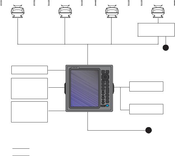
SYSTEM CONFIGURATION
|
|
|
|
|
|
|
|
|
|
|
|
|
|
|
|
|
|
|
|
|
|
|
|
|
|
|
|
|
|
|
|
|
|
|
|
|
|
|
|
|
|
|
|
|
|
Model FR-8065 |
|
Model FR-8125 |
|
Model FR-8255 |
|||||||||||||||||||||
|
Model FR-8045 |
|
Antenna Unit |
|
Antenna Unit |
|
Antenna Unit |
||||||||||||||||||||||||||||
|
XN-12A-RSB-0070-085A |
XN-12A-RSB-0070-086A |
XN-12A-RSB-0070-087A |
||||||||||||||||||||||||||||||||
|
Antenna Unit |
XN-12A-RSB-0073-085A |
XN-12A-RSB-0073-086A |
XN-12A-RSB-0073-087A |
|||||||||||||||||||||||||||||||
XN-12A-RSB-0073-088B |
XN-13A-RSB-0070-085A |
XN-13A-RSB-0070-086A |
XN-13A-RSB-0070-087A |
||||||||||||||||||||||||||||||||
XN-13A-RSB-0073-088B |
XN-13A-RSB-0073-085A |
XN-13A-RSB-0073-086A |
XN-13A-RSB-0073-087A |
||||||||||||||||||||||||||||||||
|
|
|
|
|
|
|
|
|
|
|
|
|
|
|
|
|
|
|
|
|
|
|
|
|
|
|
|
|
|
|
|
|
|
|
|
|
|
|
|
|
|
|
|
|
|
|
|
|
|
|
|
|
|
|
|
|
|
|
|
|
|
|
|
|
|
|
|
|
|
|
|
|
|
|
|
|
|
|
|
|
|
|
|
|
|
|
|
|
|
|
|
|
|
|
|
|
|
|
|
|
|
|
|
|
|
|
|
|
|
|
|
|
|
|
|
|
|
|
|
|
|
|
|
|
|
|
|
|
|
|
|
|
|
|
|
|
|
|
|
|
|
|
|
|
|
|
|
|
|
|
|
|
|
|
|
|
|
|
|
|
|
|
|
|
|
|
|
|
|
|
|
|
|
|
|
|
|
|
|
|
|
|
|
|
|
|
|
|
|
|
|
|
|
|
|
|
|
|
|
|
|
|
|
|
|
|
|
|
|
|
|
|
|
|
|
Antenna Power Supply
PSU-008
Display unit |
24 VDC |
|
RDP-154 |
|
|
Heading sensor |
|
|
Echo sounder |
Remote display |
|
GPS navigator |
||
|
||
AIS, etc. |
|
|
Echo sounder |
External buzzer |
|
GPS navigator |
||
|
||
AIS, etc. |
|
24 VDC
:Basic configuration
:Optional
xi
SYSTEM CONFIGURATION
This page is intentionally left blank.
xii

1.OPERATION
1.1Controls
The display unit has 16 keys which have labels with their functions, three knob controls and a CursorPad. When you correctly operate this equipment, the unit beeps one time. If your operation is not correct, the unit beeps three times.
MENU |
CANCEL |
HL OFF |
|
EBL |
VRM |
OFF |
TARGET |
CENTER |
ALARM |
TLL |
|
GAIN |
RANGE |
|
|
A/C SEA |
CUSTOM |
|
|
|
TRAILS |
A/C RAIN |
STBY |
|
|
|
TX |
ECONOMY |
I |
B R LL |
1 |
MENU |
CANCEL |
|
HL OFF |
|||
|
|
2
ENTER
3 |
EBL |
VRM |
|
4 |
OFF |
TARGET |
|
CENTER |
ALARM |
||
|
|||
5 |
TLL |
+ |
|
|
|
RANGE |
|
|
GAIN |
|
|
|
F1 |
|
|
6 |
|
|
|
|
A/C SEA |
CUSTOM |
|
|
|
||
|
F2 |
|
|
7 |
|
TRAILS |
|
|
|
||
|
A/C RAIN |
|
|
|
F3 |
STBY |
|
8 |
|
TX |
|
|
|
||
|
ECONOMY |
B R ILL |
|
|
|
|
No. |
Control |
Description |
|
1 |
MENU |
Open/close the menu. |
|
2 |
CursorPad |
Select the menu items and options. |
|
|
|
Move the cursor. (Shown like W,S,X |
|
|
|
& T in the manual.) |
|
3 |
EBL |
Measure the bearing to a target. |
|
4 |
OFF CENTER |
Off-center the display. |
|
|||
|
5 |
TLL |
Send the latitude and longitude of a |
|
|
|
target to a navigation plotter. Enter an |
|
|
|
origin mark at the cursor position on |
|
|
|
the radar display. |
9 |
6 |
GAIN |
Rotating: Adjust the sensitivity of the |
|
|
|
radar receiver. |
|
7 |
A/C SEA |
Rotating: Reduce the sea clutter. |
10 |
8 |
A/C RAIN |
Rotating: Reduce the rain clutter. |
|
6,7, |
F1,F2, F3 |
Push: Activate the function given to |
|
8 |
|
the key. |
|
9 |
CANCEL/HL |
Erase the heading line while you press |
11 |
|
OFF |
this key. Cancel the last entry in menu |
|
|
|
operation. Cancel the tracking of |
|
|
|
ARPA target. Remove data of select- |
12 |
|
|
ed ARPA or AIS target from the data |
|
|
|
box. Return one layer in a multiple lev- |
|
|
|
el menu. |
|
10 |
ENTER |
Save selected menu option. Acquire |
13 |
|
|
an ARPA target. Select the ARPA or |
|
|
AIS target to display its data. |
|
|
|
|
|
|
11 |
VRM |
Measure the range to a target. |
|
12 |
TARGET |
Set the target alarm, which checks for |
|
|
ALARM |
the targets in the operator-set area. |
14 |
13 |
RANGE |
Select the detection range. |
|
|
|
|
|
|
|
|
|
14 |
CUSTOM |
Set the radar controls for one-touch |
15 |
|
|
operation of radar. |
|
15 |
TRAILS |
Plot the radar echo movement. |
|
16 |
STBY/TX |
Transmit the radar pulses or put the |
16 |
|
|
radar in standby. |
|
|
|
|
|
|
|
|
|
17 |
Brill |
Short Press: Turn on the power. Adjust |
17 |
|
|
the brilliance. |
|
|
|
Long press: Turn off the power. |
|
|
|
|
1-1

1. OPERATION
1.2How to Turn the Radar On/Off and Transmit
Press the |
B R ILL |
key to turn on the radar.To turn off the radar, press and hold the key |
until the screen turns off.
When you turn on the power, the initialization screen appears followed by the start-up screen. The start-up screen shows the model name, program number and the results of the ROM and RAM check, "OK" or "NG" (No Good). If "NG" appears, contact your dealer for instruction.
Model name appears here.
Program & 0359307-XX.XX 
 version no.
Start-up screen
After the self-tests have completed, the bearing scale and a digital timer appear. The digital timer counts down the time necessary to warm the magnetron, which transmits the radar pulses. The time to warm the magnetron is 90 seconds for FR-8045/FR- 8065 and FR-8125 radars, 180 seconds for FR-8255 radar.
After the timer reads 0:00, the STBY screen appears. The STBY screen has three types. (See paragraph 1.44.2.) The radar is ready to transmit the radar pulses. Press the STBY/TX key to transmit the radar pulses.
The STBY/TX key switches between standby and transmit. The antenna rotates in transmit and is stopped in standby. The magnetron gets old with use. To increase the life of the magnetron, set the radar in standby when you do not use the radar.
Quick start
If the magnetron is still warm, you can get the radar to TRANSMIT without the warm
up time. When the |
B R ILL |
|
seconds after you turn
key is turned off by accident, turn on the off the power.
B
R
I
LL
key within 10
1-2

1. OPERATION
1.3Display Indications
Offcenter
(M: Manual, A: Auto, C: Custom)
|
|
Input source |
|
|
|
|
|
(shown when display |
Heading |
Trail reference |
|
|
|
unit functions as |
|
Trail time |
|
|
|
remote display) |
North marker |
|
|
|
|
|
|
||
Range |
1.5NM |
SLAVE HDG 3 5 0 . 0 ° TRAIL(T) |
TUNEAUTO |
Tuning indicator |
|
Range ring interval |
0.5 OFFCENT(A) |
15 S |
|
||
|
ALM1_ACK |
Target Alarm 1 (2) |
|||
Pulselength |
SP CS 1 |
|
|
||
|
|
ALM2_OUT |
|||
Display mode |
H UP |
|
|
WTC |
indications |
Zoom indication |
ZOOM(R) |
|
|
|
|
|
|
|
|
||
Custom setting |
|
|
|
|
WATCHMAN |
(1 - 3) |
|
|
|
|
Target alarm zone 1 |
|
|
|
|
|
No. 2 EBL |
Range ring |
|
|
|
|
Heading line |
Bearing scale |
|
|
|
|
|
No. 1 VRM |
|
|
|
|
No. 2 VRM |
|
|
|
|
|
|
No. 1 EBL |
|
|
|
|
|
Zoom cursor |
|
|
|
|
|
|
+ |
|
|
|
Zoom window |
Cursor |
|
|
|
|
|
Target alarm zone 2 |
|
|
|
|
|
Echo stretch |
ES 1 |
|
|
IR 1 |
Interference rejector |
Echo averaging |
EAV 1 |
|
|
A/C AUTO |
Auto adjustment of |
|
EBL |
|
|
VRM rain and sea clutters |
|
No. 1 EBL bearing |
270.0°R |
V E C T T R U E 0 5 : 0 0 |
0.889NM No. 1 VRM range |
||
No. 2 EBL bearing |
22.0°R |
+ 241.0°R |
1.592NM |
0.422NM |
No. 2 VRM range |
OWN SHIP |
|
+ CURSOR |
|
WAYPOINT |
|
LAT |
34°56.123N |
LAT |
34°56.123N |
BRG |
14.8° |
LON |
135°34.567E |
LON |
135°34.567E |
RNG |
0.876NM |
SPEED |
12.3KN |
TTG |
01:00 |
TTG |
00:20 |
Vector time
Cursor data
(Range and bearing or L/L position)
Nav data: Appears at screen bottom when [Data Box] in the [Display] menu is set to [Nav] or [All]. Appropriate sensors required to display nav data.
Display indications
1-3

1. OPERATION
1.4How to Adjust Display Brilliance, Panel Dimmer
You can adjust the display brilliance and panel dimmer as follows:
1. Press the
B
R
I
LL
key to show the [Brill/Panel] dialog box.
|
|
|
|
Brill/Panel |
|
|
|
|
||||||
|
|
|
|
|
|
|
|
|
|
|
|
|
|
|
|
|
|
|
|
|
|
|
|
|
Min |
Max |
|||
|
|
|
|
|
|
16 |
|
|
|
|
|
|
|
|
Brill |
(1~16) |
|
|
|
|
|
||||||||
Panel |
(1~ 8) |
|
8 |
|
|
|
|
|
|
|
||||
|
|
|
|
|
|
|
||||||||
Enter |
|
|||||||||||||
|
|
|
|
Select |
||||||||||
CANCEL/HL OFF Close
Brill/Panel dialog box
2.Press the [ENTER] key (or S, T) to select [Brill] or [Panel].
3.Use W or X to adjust. (For brilliance you can also use the B R ILL
4.Press the CANCEL/HL OFF key to close the window.
key.)
1.5Menu Description
This FR-8045/FR-8065/FR-8125/FR-8255 series has 15 menus and 6 sub menus. Below is the basic procedure for menu operation.
1. Press the MENU key to open the menu.
|
|
|
|
|
|
Menu |
|
Currently selected menu |
|
|
|||||||||||
|
|
|
|
|
|
|
|
|
|
|
|
|
|
|
|
|
|
|
|
|
|
Title bar* |
|
|
|
Menu |
|
|
|
|
|
|
|
|
|
|
|
|
|
|
|||
|
|
|
|
|
|
|
Brill/Color |
|
|
|
|
|
|||||||||
|
|
|
|||||||||||||||||||
Cursor* |
|
|
|
|
|
|
|
|
|
|
|
|
|
|
|
|
|
|
|
|
|
|
|
|
|
Brill/Color |
|
|
Echo Brill |
: 8 |
|
|
|
|
|
||||||||
|
|
|
|
||||||||||||||||||
|
|
|
|
Display |
|
Rings Brill |
|
: 4 |
|
|
|
|
|
||||||||
|
|
|
|
Echo |
|
Mark Brill |
|
: 4 |
|
|
|
|
|
||||||||
|
|
|
|
Custom 1 |
|
HL Brill |
|
: 4 |
|
|
|
|
Menu items |
||||||||
|
|
|
|
Custom 2 |
|
Character Brill |
|
: 4 |
|
|
|
|
|||||||||
|
|
|
|
|
|
|
|
|
|
and current |
|||||||||||
|
|
|
|
Custom 3 |
|
Echo Shading |
|
: 1 |
|
|
|
|
|||||||||
|
|
|
|
|
|
|
|
|
|
settings |
|||||||||||
|
|
|
|
Alarm |
|
Display Color |
|
: Custom |
|
|
|
||||||||||
|
|
|
|
|
|
|
|
|
|
||||||||||||
|
|
|
|
Target Trails |
|
Echo Color |
|
: Yellow |
|
|
|
|
|||||||||
|
|
|
|
Tuning |
|
Background Color |
|
: Black |
|
|
|
|
|||||||||
|
|
|
|
Others |
|
|
|
|
|
|
|
|
|
|
|
|
|||||
|
|
|
|
Target |
|
[ENTER]: Enter [CANCEL/HL OFF]: Back |
|
|
|||||||||||||
|
|
|
|
|
|
|
|
|
|
|
[MENU] Exit |
|
|
|
|
|
|
|
|||
|
|
|
|
|
|
|
|
|
|
|
|
|
|
|
|||||||
|
|
|
|
Adjusting brilliance and color |
|
|
|
|
|
|
|
|
|
||||||||
|
|
Guide |
|
|
|
|
|
Scroll bar (Indicates menus currently not shown in menu |
|||||||||||||
|
|
|
|
|
|
|
|||||||||||||||
|
|
message |
|
window. Black vertical line indicates location in menu. |
|||||||||||||||||
|
|
(The simple explanation for You can see the menus and sub menus currently not shown |
|||||||||||||||||||
|
|
|
the current menu.) |
|
by using or .) |
|
|
|
|
|
|
|
|||||||||
*: Title bar in currently controlled column is blue; cursor selection is yellow. Title bar of inactive column is gray.
Menu
1-4

1. OPERATION
2.Use S or T to select a menu or sub-menu.The cursor (yellow) in the [Menu] column indicates the menu currently selected. The menu items in the right-hand window change according to the menu selected.
Menu Description
[Brill/Color]: Adjust the brilliance and color. [Display]: Set up the display features. [Echo]: Adjust the radar echo.
[Custom 1] - [Custom 3]: Adjust the user settings. [Alarm]: Set up the alarm features.
[Target Trails]: Process the trails of radar targets. [Tuning]: Adjust the radar tuning.
[Others]: Set up other items.
[Target]: Set up the targets configuration. [ARPA]: Set up the ARPA targets.
[AIS]: Set up the AIS targets.
[GPS]: Set up the GP-320B (Black-Box GPS).
[System]
[Initial]: Initial Setting.
[Tests]: Diagnostic self test, LCD test and ARPA test. See section 6.7 to 6.9. [Sector Blanks]: Set sector blanks to prevent the transmission in a certain area. [Units]: Set up units.
[Installation] and [Factory]: For use by the installer. See Installation Manual.
3.Press the ENTER key to switch the cursor to the menu items column. The cursor in the menu column now turns gray and the cursor in the menu items column is yellow. The control moves to the menu items column.
To switch the cursor from the menu items column to the menu column, use the CANCEL/HL OFF key. The color of the title bar of the active column is blue and of the inactive column in gray.
4.Use S or T to select a menu item and press the ENTER key. A window with options for the related menu item appears.
|
|
Day |
|
|
|
|
|
|
|
|
|
Night |
|
|
|
|
8 |
|
|
|
|
Twilight |
|
|
|
|
|
|
|
|
|
Custom |
|
|
(1~8) |
|
|||
|
|
|
|
|
|
|
|
|
|
Display Color options |
Echo Brill setting window |
||||||||
Example windows
5.Use S or T to select an option or numeric value.
6.Press the ENTER key to save your selection. To close the window without saving, press the CANCEL/HL OFF key.
7.Press the MENU key to close the menu.
Note: The menus on the [IEC] and [Russian-River] types close automatically when there is no menu operation for 10 seconds, according to IEC regulations. The following menus and screens are excluded from this regulation:
[Alarm message], [Alarm status], [Tuning Init Adjust], [GPS self test], [GPS satellite monitor], [System self test], [System LCD pattern], and [Auto installation setup]. The menus do not close automatically in the [River] or [Sea] configuration.
1-5

1. OPERATION
1.6Tuning
In default, the radar receiver can be tuned automatically after you set the radar to TX.
If you require fine tuning in manual, do the following:
1.Transmit the radar and select the maximum range with the RANGE key.
2.Press the MENU key to open the menu.
3.Use S or T to select [Tuning] and press the ENTER key.
|
Menu |
|
|
|
|
Tuning |
|
|
|
|
|
|
|
|
|
|
|||
Brill/Color |
|
|
|
|
|
|
|
||
Tuning Mode |
: Auto |
|
|||||||
Display |
|
|
|
|
|
|
|||
|
Manual Tuning |
: 6.00V |
|
||||||
Echo |
|
|
Tuning Init Adjust |
|
|
||||
Custom 1 |
|
|
|
|
|
|
|
||
Custom 2 |
|
|
|
|
|
|
|
||
Custom 3 |
|
|
|
|
|
|
|
||
Alarm |
|
|
|
|
|
|
|
||
Target Trails |
|
|
|
|
|
|
|
||
Tuning |
|
|
|
|
|
|
|
||
Others |
|
|
|
|
|
|
|
||
Target |
|
[ENTER]: Enter [CANCEL/HL OFF]: Back |
|
||||||
|
|
|
|
[MENU] Exit |
|
|
|
|
|
Choosing a tuning mode
Tuning menu
4. Use S or T to select [Tuning Mode] and press the ENTER key.
Auto
Manual
Tuning Mode options
5.Use S or T to select [Manual] and press the ENTER key.
6.Use S or T to select [Manual Tuning] and press the ENTER key.
Manual Tuning setting window
7.Use S or T to adjust the tuning while you look at the tuning bar in the upper-right corner of the display. The best tuning point is where the tuning bar moves to a maximum value. The vertical bar on the tuning bar shows the tuning voltage.
TUNE MAN Tuning method (Manual)


 Tuning bar
 Vertical bar
8.Press the ENTER key.
9.Press the MENU key to close the menu.
Note: If the automatic tuning does not give the correct tuning, run the [Tuning Init Adjust] again.
1-6
1. OPERATION
1.7Display Modes
This radar has the display modes shown below. All modes except head up require a heading signal. The true motion mode additionally requires position data.
Relative Motion (RM)
•[Head Up] (H UP)
•[Course Up] (C UP)
•[North Up] (N UP)
•[True View] (TRUE VIEW)
True Motion
• [True Motion] (TM)
1.7.1How to select the display mode
1.Press the MENU key to open the menu.
2.Use S or T to select [Display] and press the ENTER key.
|
Menu |
|
|
|
|
Display |
|
|
|
|
|
|
|
|
|
||||
Brill/Color |
|
|
Display Mode |
: Head Up |
|
||||
Display |
|
|
Zoom |
: Off |
|
||||
Echo |
|
|
Zoom Mode |
: Relative |
|
||||
Custom 1 |
|
|
Offcenter Mode |
|
|
|
|||
Custom 2 |
|
|
Save Offcenter |
|
|
|
|||
Custom 3 |
|
|
Echo Area |
: Normal |
|
||||
Alarm |
|
|
Base Text Display |
: All |
|
||||
Target Trails |
|
|
Data Box |
|
|||||
Tuning |
|
|
Gain/Sea/Rain Bar |
|
|
|
|||
|
|
|
|
|
|
||||
Others |
|
|
|
|
|
|
|
||
Target |
|
[ENTER]: Enter [CANCEL/HL OFF]: Back |
|
||||||
|
|
|
|
[MENU] Exit |
|
|
|
||
Choosing the presentation mode
Display menu
3. Use S or T to select [Display Mode] and press the ENTER key.
Head Up
Course Up
North Up
True Motion
True View
4.Use S or T to select a display mode and press the ENTER key.
5.Press the MENU key to close the menu.
Note: All modes except head up require a heading signal in AD-10 format or NMEA format. If the heading signal is lost, the mode is changed to head up and the north marker disappears. The display for heading is XXX.X and the alarm sounds. The message "GYRO" (AD-10 format data) or "NMEA_HDG" (NMEA format data) appears in the alarm message display. To stop the audio alarm, press any key. When the heading signal is restored, check the heading. To check the heading, press the F3 key. When the heading signal is restored, the current heading is displayed at the heading indication.
1-7
1. OPERATION
1.7.2Description of display modes
Head up mode
A display without azimuth stabilization in which the line |
North marker |
Heading line |
|
that connects the center with the top of the display in- |
|||
|
|
||
dicates your heading. Targets are shown at their mea- |
|
|
|
sured distances and their directions relative to your |
|
|
|
heading. The short dotted line on the bearing scale is |
|
|
|
the north marker. |
|
|
Course up mode
The radar picture is stabilized and displayed with the
currently selected course at the top of the screen. |
North marker |
|
|
When you change the heading, the heading line |
|
moves with the course selected. If you select a new |
|
course, select the course up mode again to display |
|
the new course at the top of the display. Targets are |
|
shown at their measured distances and their direc- |
|
tions relative to the set course, which is at the 0-de- |
|
gree position. The heading line moves according to |
|
the yawing and any course change. |
|
North up mode |
|
|
Targets are shown at their measured distances and |
North marker |
|
their true (compass) directions from your ship. North is |
||
|
||
at the top of the screen. The heading line changes its |
|
|
direction according to your heading. |
|
Heading line
Heading line
1-8
|
1. OPERATION |
|
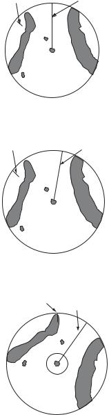
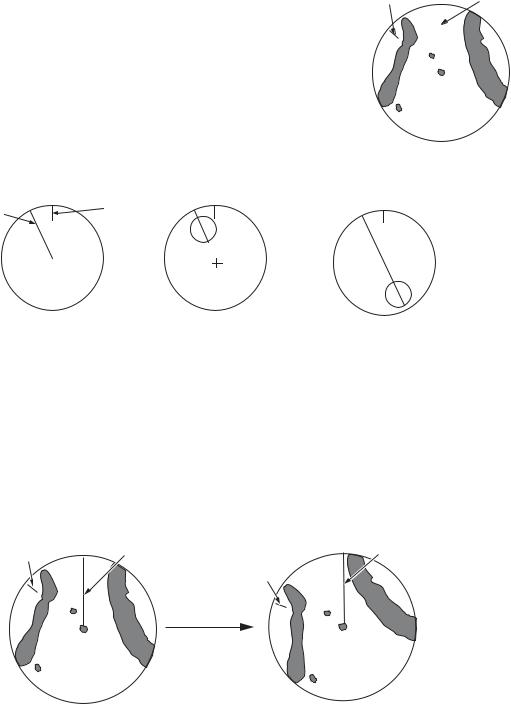
True motion mode |
|
|
Your ship and other objects in motion move with their true |
|
|
courses and speed. All fixed targets, like landmasses, ap- North marker |
|
Heading lin |
pear as fixed echoes in ground stabilized TM. When your |
|
|
ship reaches a point that is 75% of the radius of the dis- |
|
|
play, the position is reset. The ship appears at 75% radius |
|
|
opposite to the extension of the heading line on the dis- |
|
|
play center. You can manually reset your ship symbol if |
|
|
you press the OFF CENTER key. |
|
|
Heading |
North |
line |
marker |
(a) True motion |
(b) Your ship has reached a |
(c) Your ship is automatically |
is selected |
point 75% of display radius |
reset to 75% of display radius |
Example: Automatic reset of your ship marker in true motion mode
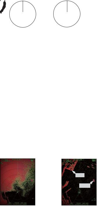
True view mode
The echoes move in real time according to the change of the heading of your ship. The heading line is at the top of the screen. When the heading signal is lost, this function is not available and the display mode automatically changes to the head up mode. The [Wiper] is not available in this mode (see section 1.31).
North marker |
Heading line |
Heading line |
|
|
North marker |
The echoes move according to the change of the heading of your ship during one sweep.
1-9

1. OPERATION
1.8How to Select a Range Scale
The selected range scale, range ring interval and pulselength are shown at the upper left corner on the screen. When an object target comes closer, reduce the range scale so that the target appears in 50-90% of the display radius.
Use the RANGE key to select range. Press the "+" part of the key to raise the range; the "-" part to lower the range.
1.9How to Adjust the Gain (sensitivity)
The gain functions to adjust the sensitivity of the receiver for the best reception. The gain is adjusted automatically or manually.
1. |
Press the MENU key to open the menu. |
|
2. |
Use S or T and select [Echo] and press the ENTER key. |
|
3. |
Use S or T to select [Gain Mode] and press the ENTER key. |
|
4. |
Use S or T to select [Auto] or [Manual] and press the ENTER key. |
Auto |
|
Manual
the window for Gain/Sea/Rain indicator shown below appears. This window closes automatically in the [River] or [Sea] mode when there
is no menu operation for ten seconds. [Auto] is for adjusting the gain automatically. For [Manual] go to "Manual mode" below.
AUTO: Auto, MAN: Manual
Gain/Sea/Rain
GAIN MAN |
|
|
|
Gain setting bar |
|
|
|
|
|||
SEA MAN |
|
|
|
|
|
RAIN MAN |
|
|
|
|
|
|
|
|
|
|
|
|
[CANCEL/HL OFF: Close |
|
|
||
Gain/Sea/Rain indicator
5.Press the CANCEL/HL OFF key to close the window.
6.Press the MENU key to close the menu.
Note: To adjust the gain finely in [Auto] mode, rotate the GAIN knob. The confirmation message appears. If you select [Yes] the mode changes to [Manual] mode. Rotate the Gain knob to adjust the gain.
Are you sure to change to manual mode?
Manual mode
1.Rotate the GAIN knob to adjust the gain so that weak noise appears on all of the screen. If the gain is too low, weak echoes are erased. If the gain is too high, the background noise hides weak targets.
2.Press the CANCEL/HL OFF key to close the window.
1-10

1. OPERATION
1.10How to Reduce the Sea Clutter
The reflected echoes from the waves appear around your ship and have the name "sea clutter". The sea clutter extends according to the height of waves and antenna above the water. When the sea clutter hides the targets, use the A/C SEA control to reduce the clutter, either manually or automatically.
Auto mode
1.Press the Menu key to open the menu.
2.Use S or T to select [Echo] and press the ENTER key.
3.Use S or T to select [Sea Mode] and press the ENTER key.
4.Use S or T to select [Auto] or [Manual] and press the ENTER key. The window for Gain/Sea/Rain indicator appears. (Refer to the illustration of step 4 in section 1.9). If you selected [Auto], go to step 5. For [Manual], go to "Manual mode" below.
5.Press the CANCEL/HL OFF key to close the window. [Auto] is used to reduce the sea clutter automatically. If the sea clutter is strong while cruising along a coastline in the [Auto] mode, go to step 6. If not, go to step 9.
6.Use S or T to select [Auto Sea] and press the ENTER key.
Coastal
Advanced
7.Use Sor Tto select [Coastal] or [Advanced] then press the ENTER key. The window for Gain/Sea/Rain indicator appears for confirmation.
[Coastal]: Suppress both land and sea clutter. For cruising along a coastline. [Advanced]: Automatically identify land echoes from sea reflections to suppress only sea reflections. Use this mode for general use.
8.Press the CANCEL/HL OFF key to close the menu.
9.Press the MENU key to close the menu,
Note: When you want to adjust the sea clutter finely in [Auto] mode, rotate the A/C SEA knob. The confirmation window appears. If you select [Yes], the mode changes to [Manual] mode. Rotate the A/C SEA knob to adjust the sea clutter.
Are you sure to change to manual mode?
Confirmation message
Manual mode
1)Rotate the A/C SEA knob to reduce the sea clutter.
Note: When the setting of the A/C SEA control is correct, the clutter is broken into small dots, and small targets become identified. If the setting is not enough, targets are hidden in the clutter. If the setting is higher than necessary, both sea clutter and targets disappear from the display. Normally adjust the control until the clutter has disappeared to leeward, but a small amount of the clutter is visible windward.
1-11

1.OPERATION
2)Press the CANCEL/HL OFF key to close the window.
Sea clutter at |
A/C SEA control adjusted; |
screen center |
sea clutter reduced |
1.11How to Reduce the Rain Clutter
The reflections from the rain or snow appear on the screen. These reflections have the name "rain clutter". When the rain clutter is strong, targets in the rain clutter are hidden in the clutter. Reflections from the rain clutter are easily identified from true targets by their wool-like appearance.The A/C RAIN control, like the A/C SEA control, adjusts the receiver sensitivity, but in longer range. If the setting is high, the rain clutter is more reduced. The rain control breaks the continuous display of rain or snow reflections into a random pattern. When the rain clutter hides the targets, adjust the rain control (automatic or manual) to reduce the clutter.
Auto mode
1.Press the MENU key to open the menu.
2.Use S or T to select [Echo] and press the ENTER key.
3.Use S or T to select [Rain Mode] and press the ENTER key.
4.Use S or T to select [Auto] or [Manual] then press the ENTER key. The window for Gain/Sea/Rain indicator appears (refer to the illustration of step 4 at
section 1.9). If you selected [Auto], go to step 5. For [Manual], go to "Manual mode" below.
5.Press the CANCEL/HL OFF key to close the window.
6.Use S or T to select [Auto Rain] and press the ENTER key.
Calm
Moderate
Rough
7.Use S or T to select [Calm], [Moderate] or [Rough] then press the ENTER key. The window for Gain/Sea/Rain indicator appears for confirmation.
[Calm]: For light rain
[Moderate]: When you cannot reduce the rain clutter with [Calm] mode [Rough]: For heavy rain
8.Press the CANCEL/HL OFF key to close the window.
9.Press the MENU key to close the menu.
Note: When you want to adjust the rain clutter finely in [Auto] mode, rotate the A/C RAIN knob. The confirmation message appears. If you select [Yes], the mode changes to [Manual] mode. Rotate the A/C RAIN knob to adjust the rain clutter.
1-12
1. OPERATION
Manual mode
1.Rotate the A/C RAIN knob to reduce the rain clutter.
2.Press the CANCEL/HL OFF key to close the window.
Rain clutter at |
A/C RAIN control adjusted; |
screen center |
rain clutter reduced |
1.12Automatic Adjustments of Sea and Rain Clutters
When you can not correctly reduce the sea clutter or rain clutter with the related control, turn on the automatic anti-clutter feature. When this feature is turned on,
"A/C AUTO" appears at the lower-right corner.
1.Press the MENU key to open the menu.
2.Use S or T to select [Echo] and press the ENTER key.
3.Use S or T to select [A/C Auto] and press the ENTER key.
4.Use S or T to select [Off] or [On] then press the ENTER key.
5.Press the MENU key to close the menu.
Caution on use
•Echoes that cover wide areas (like land and islands) can become smaller when the [A/C Auto] is used.
•When [A/C Auto] is active, the strength of a target in sea clutter or rain clutter can be lower than actual strength. In this case change to manual A/C SEA and manual A/C RAIN and adjust the picture.
Land:£:¸:Å:»
Target:£:¸:Å:»
A/C Auto: Off |
A/C Auto: On |
1-13
1. OPERATION
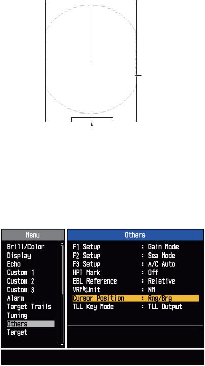
1.13Cursor
The cursor functions to find the range and bearing (default function) to a target or the latitude and longitude position of a target. Use the CursorPad to move the cursor into position and read the cursor data at the screen bottom.
0.5NM |
|
|
|
|
|
+ |
Cursor |
+ |
110.1° R |
0.488 NM |
|
Cursor data (range and bearing,
or latitutde and longitude)
Cursor data
You can show the cursor data as range and bearing (from your ship to the cursor) or latitude and longitude. Position and heading signal are required.
1.Press the MENU key to open the menu.
2.Use S or T to select [Others] and press the ENTER key.
|
Menu |
|
|
|
Others |
|
|
|
|
|
|
|
|
|
|
|
|
F1 Setup |
|
: Gain Mode |
Brill/Color |
||||||
Display |
|
F2 Setup |
|
: Sea Mode |
||
|
F3 Setup |
|
: A/C Auto |
|||
Echo |
|
|
||||
Custom 1 |
|
WPT Mark |
|
: Off |
||
Custom 2 |
|
EBL Reference |
|
: Relative |
||
Custom 3 |
|
VRM Unit |
|
: NM |
||
Alarm |
|
Cursor Position |
|
: Rng/Brg |
||
Target Trails |
|
TLL Key Mode |
|
: TLL Output |
||
Tuning |
|
|
|
|
||
Others |
[ENTER]: Enter [CANCEL/HL OFF]: Back |
|||||
Target |
||||||
|
|
|
|
|
|
|
[MENU] Exit
Choosing display mode of cursor position
Others menu
1-14

1. OPERATION
3. Use S or T to select [Cursor Position] and press the ENTER key.
Rng/ Brg
Lat/Lon
Cursor Position options
4.Use Sor Tto select [Rng/Brg] (Range/Bearing) or [Lat/Lon] (Latitude/Longitude) then press the ENTER key. (When the navigation data box display is set to [Nav] or [All] in the [Display] menu, cursor latitude and longitude position cannot be displayed in the cursor data box.)
5.Press the MENU key to close the menu.
1.14Interference Rejector
The radar interference can occur when your ship is near the radar of another ship that operates on the same frequency band with your radar. The interference shows on the screen as many bright dots. The dots can be random or in the shape of dotted lines that run from the center to the edge of the display. You can identify the interference from the normal echoes, because the interference does not appear in the same location at the next antenna rotation. When this feature is turned on, "IR 1", "IR 2" or "IR 3" appears at the lower-right corner.
Interference
1.Press the MENU key to open the menu.
2.Use S or T to select [Echo] and press the ENTER key.
3.Use S or T to select [Int Rejector] and press the ENTER key.
Off
1
 IR 1
IR 1
2
 IR 2
IR 2
3
 IR 3
IR 3
Indication at the lower-right corner of the display
4.Use S or T to select [Off], [1], [2] or [3] then press the ENTER key. [3] removes the interference the most.
5.Press the MENU key to close the menu.
Note: When there is no interference, turn off the interference rejector so you do not miss the small targets.
1-15

1. OPERATION
1.15How to Measure the Range to a Target
You can measure the range to a target in three methods. You can use the fixed range rings, the cursor (if set to measure range and bearing) and the VRM (Variable Range Marker).
Use the fixed range rings to get a rough estimate of the range to a target. The fixed range rings are the concentric solid circles about your ship. The number of rings changes with the selected range scale. The interval of the range ring is displayed at the upper-left corner of the screen. Count the number of rings between the center of the display and the target. Check the range ring interval and measure the distance of the echo from the nearest ring.
1.15.1How to adjust range ring brilliance
1.Press the MENU key to open the menu.
2.Use S or T to select [Brill/Color] and press the ENTER key.
3.Use S or T to select [Rings Brill] and press the ENTER key.
|
Menu |
|
|
|
Brill/Color |
|
|||
|
|
|
|
|
|
|
|
|
|
|
Brill/Color |
|
|
|
Echo Brill |
|
: 8 |
|
|
|
Display |
|
|
|
Rings Brill |
|
: 4 |
|
|
|
|
|
|
Mark Brill |
|
: 4 |
|
|
|
|
Echo |
|
|
|
|
|
|
||
|
Custom 1 |
|
|
|
HL Brill |
|
: 4 |
|
|
|
Custom 2 |
|
|
|
Character Brill |
|
: 4 |
|
|
|
Custom 3 |
|
|
|
Echo Shading |
|
: 1 |
|
|
|
Alarm |
|
|
|
Display Color |
|
: Custom |
|
|
|
Target Trails |
|
|
|
Echo Color |
|
: Yellow |
|
|
|
Tuning |
|
|
|
Background Color |
|
: Black |
|
|
|
Others |
|
|
|
|
|
|
|
|
|
Target |
|
|
|
[ENTER]: Enter [CANCEL/HL OFF]: Back |
|
|||
|
|
|
|
|
[MENU] Exit |
|
|
|
|
Adjusting range ring brilliance
Brill/Color menu
4.Use Sor Tto select an option and press the ENTER key. [4] is the brightest. [Off] turns off the range rings.
Off 1 2 3
4
Rings/Brill options
5. Press the MENU key to close the menu.
1-16
Loading...