


 Loading...
Furuno NAVPILOT 700, NAVPILOT 700-OB, NAVPILOT 711C, NAVPILOT 711C-OB, NAVPILOT 720 Installation Instructions
...Installation Manual
AUTOPILOT
Model NAVpilot-700/711/720/711C
SYSTEM CONFIGURATION......................... |
ii |
||
EQUIPMENT LISTS...................................... |
iii |
||
1. HOW TO INSTALL THE UNITS ............ |
1-1 |
||
1.1 |
Control Unit FAP-7001/FAP-7011 ...... |
1-1 |
|
|
1.1.1 |
Surface mount .......................... |
1-2 |
|
1.1.2 |
Desktop mount ......................... |
1-4 |
1.2 |
Processor Unit FAP-7002................... |
1-5 |
|
1.3 |
Rudder Reference Unit FAP-6112...... |
1-7 |
|
1.4 |
Remote Controllers (option)................ |
1-9 |
|
1.5 |
Distributor FAP-6800 (option)........... |
1-12 |
|
1.6 |
Control Unit FAP-7021...................... |
1-13 |
|
1.7 |
Cable Extension Kit |
|
|
|
FAP-7822 (option) ............................ |
1-13 |
|
2. WIRING |
.................................................. |
2-1 |
|
2.1 |
General Wiring.................................... |
2-1 |
|
2.2 |
Processor Unit .................................... |
2-2 |
|
|
2.2.1 |
Connections inside the |
|
|
|
processor unit........................... |
2-2 |
|
2.2.2 |
How to fasten cables to the |
|
|
|
cable clamps............................. |
2-3 |
|
2.2.3 |
How to put wires into the |
|
|
|
connector blocks....................... |
2-4 |
|
2.2.4 |
How to terminate of |
|
|
|
NMEA2000 connection............. |
2-5 |
|
2.2.5 |
Power and motor cables........... |
2-5 |
|
2.2.6 |
Teleflex linear sensor ............... |
2-7 |
|
2.2.7 |
CAN bus power ........................ |
2-8 |
|
2.2.8 |
Connection to TB4.................... |
2-8 |
2.3 |
Control Unit......................................... |
2-8 |
|
2.4 |
Remote Controllers (option)................ |
2-9 |
|
|
2.4.1 |
Example remote controller |
|
|
|
connections ............................ |
2-10 |
|
2.4.2 |
Prohibited remote controller |
|
|
|
connections ............................ |
2-11 |
2.5 |
Input/Output Sentences.................... |
2-12 |
|
3. INITIAL SETTINGS....................................... |
3-1 |
|||
3.1 |
About Initial Settings, Menu Operation...... |
3-1 |
||
3.2 |
How to Select Language and Units, |
|
||
|
Open the Installation Menu........................ |
3-2 |
||
3.3 |
Display Setup ............................................ |
3-4 |
||
3.4 |
Ship’s Characteristics Menu...................... |
3-5 |
||
3.5 |
Dockside Setup Menu ............................... |
3-6 |
||
|
3.5.1 |
Dockside setup for RRU.................. |
3-6 |
|
|
3.5.2 |
Dockside setup for Fantum |
|
|
|
|
|
FeedbackTM .................................. |
3-11 |
|
3.5.3 |
How to set the safe helm |
|
|
|
|
|
mode and power assist mode ....... |
3-13 |
|
3.5.4 |
Confirmation of the dockside |
|
|
|
|
|
setup.............................................. |
3-16 |
3.6 |
CAN bus Port Setup ................................ |
3-19 |
||
3.7 |
NMEA0183 Port Setup ............................ |
3-20 |
||
3.8 |
Sensor Setup........................................... |
3-22 |
||
3.9 |
Universal Port Setup................................ |
3-23 |
||
3.10 |
Sea Trial .................................................. |
3-25 |
||
3.11 |
Data Calibration....................................... |
3-27 |
||
3.12 |
PARAMETER SETUP Menu .................. |
3-28 |
||
3.13 |
AUTO OPTION Menu.............................. |
3-32 |
||
3.14 |
NAV OPTION Menu ................................ |
3-33 |
||
3.15 |
FISH HUNTER OPTION Menu or |
|
||
|
WIND OPTION Menu .............................. |
3-35 |
||
|
3.15.1FISH HUNTER OPTION menu ..... |
3-35 |
||
|
3.15.2WIND OPTION menu.................... |
3-36 |
||
3.16 |
SYSTEM SETUP Menu........................... |
3-37 |
||
3.17 |
RC (Remote Controller) SETUP Menu.... |
3-38 |
||
3.18 |
All Clear................................................... |
3-38 |
||
JIS CABLE GUIDE......................................... |
AP-1 |
|||
PACKING LISTS .............................................. |
A-1 |
|||
OUTLINE DRAWINGS ..................................... |
D-1 |
|||
INTERCONNECTION DIAGRAM..................... |
S-1 |
|||
MOUNTING TEMPLATES |
|
|||
|
|
|
|
|
|
|
|
|
|
www.furuno.com
All brand and product names are trademarks, registered trademarks or service marks of their respective holders.

The paper used in this manual is elemental chlorine free.
FURUNO Authorized Distributor/Dealer
9-52 Ashihara-cho,
Nishinomiya, 662-8580, JAPAN
All rights reserved. |
Printed in Japan |
A : JAN . 2010
J : OCT . 24, 2013
Pub. No. IME-72720-J
(REFU ) NAVpilot-700 Series
0 0 0 1 7 1 8 1 3 1 8

 SAFETY INSTRUCTIONS
Please read these safety instructions before you install the equipment.
|
WARNING |
Indicates a condition that can cause death or serious injury if |
|
|
|
not avoided. |
|
|
|
|
|
|
|
|
|
|
|
|
|
|
CAUTION |
Indicates a condition that can cause minor or moderate injury if |
|
|
|
not avoided. |
|
|
|
|
|
|
|
|
|
Warning, Caution |
Prohibitive Action |
Mandatory Action |
|
|
|
|
|
|
 WARNING
Turn off the power at the switchboard before beginning the installation.
Fire or electrical shock can result if the power is left on.
Use the proper power cable.
Use JIS type DPY-2.5 or the equivalent. Other types can cause fire.
Confirm that no one is near the rudder when bleeding air from oil cylinder.
The rudder may move unexpectedly, possibly causing bodily injury.
When connecting a geomagnetism detection type heading sensor, correct magnetic field deviation.
If an autopilot is used without the compensation, unexpected course change may occur.
Set REMOTE CONTROLLER 1/2 on SYSTEM SETUP menu properly according to remote controller connected.
If not done properly, malfunction may occur. Especially, take care when setting the NFU-type remote controller.
 CAUTION
Confirm that the power supply voltage is compatible with the voltage rating of the equipment.
Connection to the wrong power supply can cause fire or damage the equipment.
Observe the following compass safe distances to prevent interference to a magnetic compass:
|
|
Standard |
Steering |
|
|
|
compass |
compass |
|
|
|
|
|
|
|
FAP-7001 |
0.35 m |
0.30 m |
|
Control |
|
|
|
|
|
|
|
||
Unit |
FAP-7011 |
0.35 m |
0.30 m |
|
|
|
|
|
|
|
FAP-7011C |
0.50 m |
0.35 m |
|
|
|
|
|
|
|
FAP-7021 |
0.35 m |
0.30 m |
|
|
|
|
|
|
Processor Unit |
0.45 m |
0.30 m |
||
FAP-7002 |
||||
Remote |
|
0.30 m |
0.30 m |
|
controllers |
||||
|
|
|||
Separate the reversible pump at least one meter from communications equipment, communications antenna and communications cabling to prevent interference.
i
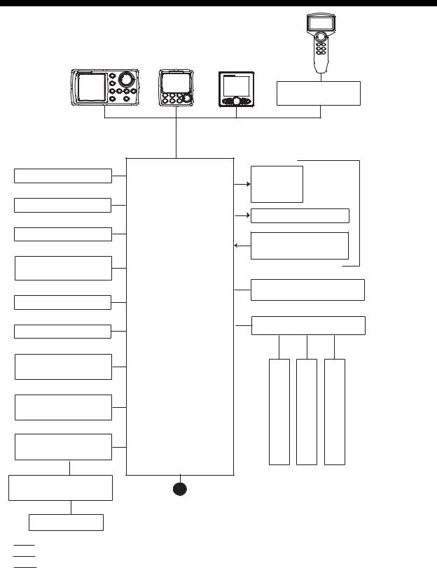
SYSTEM CONFIGURATION
CONTROL UNIT
FAP-7001
CONTACT SIGNAL IN
CONTACT SIGNAL OUT
PC (for serviceman)
HEADING SENSOR
PG-700
EXTERNAL BUZZER
EVENT SWITCH
NAV EQUIPMENT (NMEA 0183)
CANBUS EQUIPMENT (NMEA 2000)
IPS INTERFACE UNIT
IF-700IPS
VOLVO IPS GATEWAY AUTOPILOT GATEWAY
EVC System*4
:STANDARD
:OPTION
:USER SUPPLY
CONTROL UNIT |
CONTROL UNIT |
|
FAP-7011 |
FAP-7011C |
|
|
|
JUNCTION BOX |
|
|
FAP-7822 |
|
|
CONTROL UNIT QTY |
Select one |
FAP-7001/7011: MAX. 6*1 |
|
FAP-7021: MAX. 2 |
||
SOLENOID
VALVE
SHIP'S
HYDRAULIC LINEAR DRIVE
STEERING
SYSTEM*3
RUDDER REFERENCE UNIT
FAP-6112*2
REMOTE CONTROLLER
DISTRIBUTOR FAP-6800
PROCESSOR UNIT
FAP-7002
REMOTE CONTROLLER |
REMOTE CONTROLLER |
REMOTE CONTROLLER |
REMOTE CONTROLLER:
DIAL TYPE: FAP-5551, FAP-5552 BUTTON TYPE: FAP-6211, FAP-6212
12-24 VDC LEVER TYPE: FAP-6221, FAP-6222 DODGE TYPE: FAP-6231, FAP-6232
*1 : Any combination of control units is available. For FAP-7021, connect at the end of series. *2 : Not required for Fantum FeedbackTM.
*3 : Not required for the VOLVO IPS drive equipped vessel.
*4 : For the EVC system available with the NAVpilot, contact your dealer.
ii

EQUIPMENT LISTS
Standard supply for NAVpilot-700
Name |
Type |
|
Code No. |
Qty |
Remarks |
|
|
|
|
|
|
|
|
Control Unit |
FAP-7001 |
|
- |
1 |
|
|
Processor Unit |
FAP-7002 |
|
- |
1 |
|
|
Rudder Refer- |
FAP-6112-200 |
|
- |
1 |
May or may not be supplied depend- |
|
ence Unit |
|
|
|
|
ing on order. |
|
Installation |
CP64-02900 |
|
000-016-414 |
1 |
For Control Unit, w/cable assy. BD- |
|
Materials |
|
|
|
|
07AFFM-LR-150 and CP64-02901 |
|
|
CP64-03101 |
|
001-082-720 |
1 |
For Processor Unit |
|
|
CP64-02601 |
|
009-001-170 |
1 |
For Rudder Reference Unit |
|
|
|
|
|
|
May or may not be supplied depend- |
|
|
|
|
|
|
ing on order. |
|
Spare Parts |
SP64-01501 |
|
001-082-710 |
1 |
For Processor Unit, fuse |
|
Accessories |
FP64-01401 |
|
001-082-700 |
1 |
For Control Unit |
|
VOLVO Interfece |
FAP-6300 |
|
000-022-971 |
1 |
May or may not be supplied depend- |
|
Kit |
|
|
|
|
ing on order. |
|
Standard supply for NAVpilot-711 |
|
|
|
|
||
|
|
|
|
|
|
|
Name |
Type |
|
Code No. |
Qty |
Remarks |
|
|
|
|
|
|
|
|
Control Unit |
FAP-7011 |
|
- |
1 |
|
|
Processor Unit |
FAP-7002 |
|
- |
1 |
|
|
Rudder Refer- |
FAP-6112-200 |
|
- |
1 |
May or may not be supplied |
|
ence Unit |
|
|
|
|
depending on order. |
|
Installation |
CP64-03000 |
|
000-016-415 |
1 |
For Control Unit, w/cable assy. BD- |
|
Materials |
|
|
|
|
07AFFM-LR-150 and CP64-03001 |
|
|
CP64-03101 |
|
001-082-720 |
1 |
For Processor Unit |
|
|
CP64-02601 |
|
009-001-170 |
1 |
For Rudder Reference Unit |
|
|
|
|
|
|
May or may not be supplied |
|
|
|
|
|
|
depending on order. |
|
Spare Parts |
SP64-01501 |
|
001-082-710 |
1 |
For Processor Unit, fuse |
|
Accessories |
FP64-01401 |
|
001-082-700 |
1 |
For Control Unit |
|
VOLVO Interfece |
FAP-6300 |
|
000-022-971 |
1 |
May or may not be supplied |
|
Kit |
|
|
|
|
depending on order. |
|
iii
Standard supply for NAVpilot-720
Name |
Type |
Code No. |
Qty |
Remarks |
||
|
|
|
|
|
|
|
Control Unit |
FAP-7021 |
- |
1 |
|
|
|
Processor Unit |
FAP-7002 |
- |
1 |
|
|
|
Rudder Refer- |
FAP-6112-200 |
- |
1 |
|
w/20 m cable |
|
ence Unit |
|
|
|
|
|
|
|
|
|
|
|
|
|
Installation |
CP64-03101 |
001-082-720 |
1 |
|
For Processor Unit |
|
Materials |
|
|
|
|
|
|
CP64-02601 |
009-001-170 |
1 |
|
For Rudder Reference Unit |
||
Spare Parts |
SP64-01501 |
001-082-710 |
1 |
|
For Processor Unit, fuse |
|
Accessories |
FP64-01411 |
001-082-770 |
1 |
|
For Control Unit |
|
Standard supply for NAVpilot-711C |
|
|
|
|
||
|
|
|
|
|
|
|
Name |
Type |
|
Code No. |
Qty |
|
Remarks |
|
|
|
|
|
|
|
Control Unit |
FAP-7011C |
|
- |
1 |
|
|
Processor Unit |
FAP-7002 |
|
- |
1 |
|
|
Rudder Refer- |
FAP-6112-200 |
|
- |
1 |
|
May or may not be supplied |
ence Unit |
|
|
|
|
|
depending on order. |
Installation |
CP64-03101 |
|
001-082-720 |
1 |
|
For Processor Unit |
Materials |
|
|
|
|
|
|
CP64-02601 |
|
009-001-170 |
1 |
|
For Rudder Reference Unit |
|
|
|
|
|
|
|
May or may not be supplied |
|
|
|
|
|
|
depending on order. |
Spare Parts |
SP64-01501 |
|
001-082-710 |
1 |
|
For Processor Unit, fuse |
Sponge |
TZ8103008A |
|
- |
1 |
|
For Control Unit, installation materi- |
|
|
|
|
|
|
als |
Cable Assy. |
BD-07AFFM- |
|
001-081-180-10 |
1 |
|
|
|
LR-150 |
|
|
|
|
|
Terminator |
BD-07AFFM- |
|
001-081-140-10 |
1 |
|
For Control Unit, accessory |
|
LR-7001 |
|
|
|
|
|
VOLVO Interfece |
FAP-6300 |
|
000-022-971 |
1 |
|
May or may not be supplied |
Kit |
|
|
|
|
|
depending on order. |
iv
Optional supply
Name |
Type |
Code No. |
Remarks |
|
|
|
|
Control Unit |
FAP-7001 |
- |
Max. 5 optional units |
|
FAP-7011 |
- |
Max. 5 optional units |
|
FAP-7021 |
- |
Max. 2 optional units |
|
FAP-7011C |
- |
Max. 5 optional units |
Remote |
FAP-5551 |
- |
Dial type, w/connector |
Controller |
|
|
|
FAP-5552 |
- |
Dial type, no connector |
|
|
FAP-6211 |
- |
Button type, w/connector |
|
FAP-6212 |
- |
Button type, no connector |
|
FAP-6221 |
- |
Lever type, w/connector and |
|
|
|
w/CP64-01100 |
|
FAP-6222 |
- |
Lever type, no connector, |
|
|
|
w/CP64-01100 |
|
FAP-6231 |
- |
Dodge type, w/connector |
|
FAP-6232 |
- |
Dodge type, no connector |
VOLVO |
FAP-6300 |
000-022-971 |
For the IPS drive equipped |
Interface Kit |
|
|
vessel |
IPS Inter- |
IF-700IPS |
000-022-972 |
|
face unit |
|
|
|
|
|
|
|
VOLVO IPS |
AUTOPILOT-GATEWAY |
000-022-974 |
|
Gateway |
|
|
|
Distributor |
FAP-6800 |
000-090-242 |
For connection of three remote |
|
|
|
controllers |
Terminator |
BD-07AFFM-LR7001 |
001-081-140-10 |
|
Cable Assy |
MJ-A10SPF0001-060+ |
001-081-150-10 |
For Distributor Unit, 6 m |
|
MJ-A10SPF0001-120+ |
001-081-160-10 |
For Distributor Unit, 12 m |
|
BD-07AFFM-LR-100 |
001-081-170-10 |
For Control Unit, 10 m, |
|
|
|
connector at one end |
|
|
|
|
|
BD-07AFFM-LR-150 |
001-081-180-10 |
For Control Unit, 15 m, |
|
|
|
connector at one end |
|
BD-07AFFM-LR-200 |
001-081-190-10 |
For Control Unit, 20 m, |
|
|
|
connector at one end |
|
BD-07AF-07AF-LR-100 |
001-081-200-10 |
For Control Unit, 10 m, |
|
|
|
connector at both ends |
|
|
|
|
|
BD-07AF-07AF-LR-200 |
001-081-210-10 |
For Control Unit, 20 m, |
|
|
|
connector at both ends |
|
M12-05BFFM-010 |
000-167-965-10 |
CAN bus drop cable, 1 m, |
|
|
|
micro |
|
M12-05BFFM-020 |
000-167-966-10 |
CAN bus drop cable, 2 m, |
|
|
|
micro |
|
|
|
|
|
M12-05BFFM-060 |
000-167-967-10 |
CAN bus drop cable, 6 m, |
|
|
|
micro |
|
CB-05BFFM-010 |
000-167-971-10 |
CAN bus drop cable, 1 m, mini |
|
CB-05BFFM-020 |
000-167-972-10 |
CAN bus drop cable, 2 m, mini |
|
CB-05BFFM-060 |
000-167-973-10 |
CAN bus drop cable, 6 m, mini |
T-type |
SS-050505-FMF-TS001 |
000-168-603-10 |
For CAN bus, micro+micro |
Connector |
|
|
|
NC-050505-FMF-TS001 |
000-160-507-10 |
For CAN bus, mini+micro |
v
Name |
Type |
Code No. |
Remarks |
|
|
|
|
Termination |
LTWMC-05BMMT-SL8001 |
000-168-604-10 |
For CAN bus, micro, male |
Resistor |
|
|
|
LTWMN-05AMMT-SL8001 |
000-160-508-10 |
For CAN bus, mini, male |
|
|
LTWMC-05BFFT-SL8001 |
000-168-605-10 |
For CAN bus, micro, female |
|
LTWMN-05AFFT-SL8001 |
000-160-509-10 |
For CAN bus, mini, female |
Cable |
FAP-7822 |
000-016-670 |
|
Extension |
|
|
|
Kit |
|
|
|
Cradle |
FP64-01411 |
001-082-770 |
|
Flush |
FAP-7001-FLUSH-KIT |
001-082-730 |
For FAP-7001 |
Mount Kit |
|
|
|
FAP-7011-FLUSH-KIT |
001-082-740 |
For FAP-7011 |
|
Bracket |
FAP-7001-BRACKET |
001-082-750 |
For FAP-7001, w/bracket and |
|
|
|
two knob bolts |
|
|
|
|
|
FAP-7011-BRACKET |
001-082-760 |
For FAP-7011, w/bracket and |
|
|
|
two knob bolts |
Rudder Ref- |
FAP-6112-200 |
- |
w/20 m cable |
erence Unit |
|
|
|
Junction |
FI-5002 |
000-010-765 |
w/self-tapping screws |
Box |
|
|
|
|
|
|
|
Bracket |
OP64-2 |
009-004-030 |
For FAP-5551/5552 |
Assembly |
|
|
|
Flush |
OP64-4 |
009-005-790 |
For FAP-6221/6222, panel |
Mount Kit |
|
|
type |
|
OP64-5 |
009-005-800 |
For FAP-6221/6222, surface |
|
|
|
type |
Notice for discontinued models
The autopilot NAVpilot-711/720 are discontinued.
vi

1.HOW TO INSTALL THE UNITS
Note: For how to install the Control Unit FAP-7011C, see the operator’s manual (OME72780).
1.1Control Unit FAP-7001/FAP-7011
•The Control Unit can be installed three ways:
•Surface mount (fixed from front panel or fixed from rear panel (FAP-7011 only))
•Desktop mount, and
•Flush mount (Optional kit required, instructions, supplied separately).
|
|
Control Unit-FAP-7001 |
Control Unit FAP-7011 |
Select a mounting location for the Control Unit, keeping the following in mind.
•Select a location with good ventilation.
•Shock and vibration must be the least possible.
•Use the supplied display hard cover when the system is not in use.
•Do not install the display unit under "Plexiglas" or other type of shielding material. Plexiglas can trap heat and moisture or magnify sunlight energy onto the surface of the display.
•For maintenance and checking purposes, leave space at the sides and rear of the unit and leave slack in cables. See the outline drawing for recommended maintenance space.
•Observe the compass safe distances shown in the safety instructions on page i to prevent interference to a magnetic compass.
1-1

1. INSTALLATION
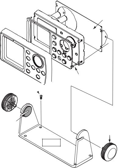
1.1.1Surface mount
There are two types of surface mounts: Fasten from front panel and fasten from rear panel (FAP-7011 only).
How to fasten Control Unit from front panel (FAP-7001/FAP-7011)
1.Using the surface mount template at the back of this manual, open a mounting hole in the installation site.
2.Detach the front panel together with the keypad assy. Attach the sponge (supplied) to the rear of display unit.
3.Set the Control Unit to the mounting hole, and fasten the unit with four self-tapping screws (3x20, supplied).
4.Attach the front panel and keypad assy. to the Control Unit.
Front Panel |
Mounting |
|
Keypad Assy. |
||
Hole |
||
|
 Sponge
Control Unit
FAP-7001
How to detach front panel
Procedure is similar for FAP-7001.
Front Panel
Remover
1.Set remover to notch on upper side of unit.
2.Pull remover to raise panel slightly.
3.Similarly use remover to raise panel at lower side.
4.Detach panel with hands.
Control Unit
FAP-7011
Self-tapping Screw (3x20, 4 pcs.)
Self-tapping screw (3x20, 4 pcs.)
Mounting
Hole
 Sponge
Keypad Assy.
1-2
1. INSTALLATION
How to fasten Control Unit from rear panel (FAP-7011 only)
1.Using the surface mount template at the back of this manual, open a mounting hole in the installation site.
2.Set studs (M3x40, 2 pcs, supplied) in the holes marked in the illustration below. (Use only the studs supplied.)
Insert stud here.
3.Set the unit to the mounting hole. Fasten the unit with the flat washers, spring washers and wing nuts (supplied).
Mounting |
|
Hole |
Wing Nut (M3) |
|
Spring Washer |
|
Flat Washer |
Stud (M3x40)
1-3
1. INSTALLATION
1.1.2Desktop mount
Use the optional bracket installation kit to install the Control Unit on a desktop or the overhead.
Bracket installation kit for FAP-7001
Type: FAP-7001-BRACKET, Code No.: 001-082-750
Name |
Type |
Code No. |
Qty |
|
|
|
|
Bracket |
64-028-1201-1 |
100-352-221-10 |
1 |
Connecting plate |
64-028-1201-1 |
100-356-381-10 |
1 |
Knob |
64-028-1203-0 |
100-352-240-10 |
2 |
Self-tapping screw |
4x16 |
000-162-605-10 |
4 |
Pan head screw |
M3x12 |
000-163-809-10 |
4 |
Liner |
64-026-1033 |
100-321-340-10 |
2 |
Bracket installation kit for FAP-7011
Type: FAP-7011-BRACKET, Code No.: 001-082-760
Name |
Type |
Code No. |
Remarks |
|
|
|
|
Bracket |
64-028-3201-1 |
100-352-281-10 |
1 |
Connecting plate |
64-028-3202-1 |
100-356-451-10 |
1 |
Knob |
64-1028-1203-0 |
100-352-240-10 |
2 |
Self-tapping screw |
4x16 |
000-162-605-10 |
4 |
Pan head screw |
M3x12 |
000-163-809-10 |
4 |
Liner |
64-026-1033 |
100-321-340-10 |
2 |
Procedure
The procedure shown below shows how to install the FAP-7001. The procedure for the FAP-7011 is similar.
1.Fasten the bracket to the mounting location with four self-tapping screws (supplied with option).
2.Detach the front panel and keypad assy., following the instructions provided.
3.Attach the connecting plate at the back of the Control Unit with four pan head screws (supplied).
4.Screw knob bolts in connection plate, set the unit to the bracket, and tighten the knob bolts.
5.Attach the front panel and keypad assy.
1-4
1. INSTALLATION
6. Attach the hard cover to protect the LCD.
Connecting plate
Pan head screw Self-tapping screw 

 (M3x12, supplied) (4x16, supplied)
Liner
Knob
Bracket
1.2Processor Unit FAP-7002
This unit can be installed on a desktop or on a bulkhead. Select a mounting location considering the following points:
•Install the unit away from direct sunlight and water splash.
•Select a location where temperature and humidity are moderate and stable.
•Consider the length of the cable connected between the Processor Unit and other units.
•Install the unit where you can easily remove the cover and access controls and connectors.
•For the installation on a bulkhead, make sure the mounting location is strong enough to support the unit under the pitching and rolling normally found on the boat.
•To prevent interference, separate the processor unit and its cables at least one meter from communications equipment, communications antennas and cables for communications equipment.
1-5

1. INSTALLATION
•Make sure there are no objects near the vent.
•Leave enough space around the unit for maintenance and servicing. The recommended maintenance space appears in the outline drawing at the back of this manual.
•Observe the compass safe distances shown in the safety instructions on page i to prevent interference to a magnetic compass.
Install the unit as follows:
Tabletop: Fasten with four self-tapping screws.
Bulkhead: Screw in two self-tapping screws for the upper side. Leave approximately 5 mm of the screws exposed. Hang unit on screws and tighten screws. Screw in two selftapping screws for lower side and tighten.
.24") |
12(0.47") |
R6(0 |
|
|
|
144±1(56.7"±0.03") |
219(8.62") |
|
2-φ5 |
44 |
(1.73") |
|
(0.2") |
|
|
|
(FIXING |
|
|
|
HOLE) |
|
|
|
EARTH |
|
|
|
TERMINAL |
|
|
|
|
230±1(9.06"±0.03") |
|
|
VENT |
CABLE INLET |
#70(2.75") |
|
#70(2.75") |
255(10.0") |
||
|
|
|
|
259(10.2")
#85(3.34")
90(3.54")
1-6
1. INSTALLATION
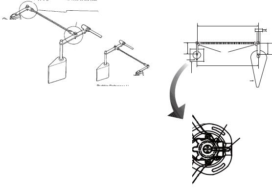
1.3Rudder Reference Unit FAP-6112
Note 1: This unit is not required for Fantum FeedbackTM. For details of Fantum FeedbackTM, see “Fantum FeedbackTM“ (page 1-8).
•Leave sufficient space around all moving parts.
•The unit must be fastened to the rudder as shown below, where the following conditions are met:
350 mm(13.8”) <Y2 < 540 mm(21.3”)
X1 = X2
Y1 = Y2
Use four self-tapping screws (supplied) to fasten the rudder reference unit.
90 degrees
|
Y2 |
X1 |
X2 |
Arrow |
90° |
mark |
Y1 |
|
|
|
RRU |
RRU may be installed at |
Rudder |
|
|
either side of rudder. |
Top view |
|
|
Align the notch on the shaft with |
Notch |
|
|
the arrow mark as shown below. |
Arrow mark |
After mounting the RRU unit adjust it as follows:
1.Center the rudder.
2.With the rudder centered, check if the notch is aligned with the arrow mark. If it is, no further adjustment is necessary. If not, go to step 3.
3.Loosen the screw on the arm of the RRU then align notch with the arrow mark.
4.Tighten the screw.
1-7
1. INSTALLATION
Relationship between reversing pump flow rate and steering cylinder capacity
The table below shows a rough guideline to determine the proper reversing pump flow rate to match with the hydraulic steering cylinder capacity. Your experience with specific boat designs may cause you to select a pump/cylinder relationship outside of the range of these guidelines.
Pump spec. |
Hardover to Hardover is 70° |
Hardover to Hardover is 90° |
|
|
|
1.0 cu. in./sec. pump |
5.85 to 17.5 cu. in. |
7.5 to 22.5 cu. in. |
1.6 cu. in./sec. pump |
9.36 to 28.0 cu. in. |
12.0 to 36.0 cu. in. |
If the hydraulic cylinder capacity is much smaller than the recommended values in the table, the rudder turning speed may be too fast for the pilot to deliver proper performance. The rudder deadband will decrease and the NAVpilot may not apply enough voltage for the pump motor to start because the applied "duty cycle" will be too low.
If the hydraulic cylinder capacity is much larger than the recommended values in the table, the rudder turning speed may be too slow to allow the NAVpilot to control the boat effectively.
Fantum FeedbackTM
Fantum FeedbackTM means the NAVpilot is controlled without the rudder reference unit. For Fantum FeedbackTM, keep the following in mind.
•The ship motor is outboard.
•The length of the ship is between 20 ft and 40 ft.
•The [DRIVE UNIT SELECTION] should be set to [REVERSIBLE 24V (or 12V)] or [SAFE HELM 24V (or 12V)].
The functions and modes shown below are not available.
•FU dodge mode
•FishHunterTM mode
•Wind mode
•Remote controllers
1-8
1. INSTALLATION
1.4Remote Controllers (option)
Two remote controllers may be connected to the Processor Unit. To connect three NFU- (Non-Follow Up) type remote controllers (button and lever) to the Processor Unit, connect them via the optional Distributor FAP-6800.
Keep the remote controllers away from areas subject to rain and water splash.
Note: For Fantum FeedbackTM, the remote controller can not be connected.
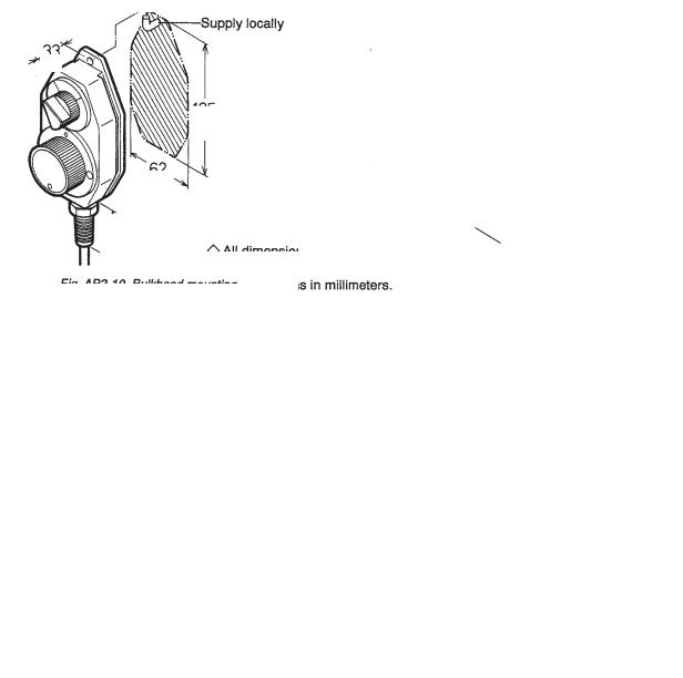
Dial-type remote controller FAP-5551/FAP-5552
Fasten these remote controllers to a bulkhead. They can also be mounted on the bulkhead by using the optional bracket assembly OP64-2 (Code No.: 009-004-030).
33
(1.3”)
125
(4.92”)
62
(2.44”)
Bulkhead mount
70(2.76”) 60(2.36”)
119(4.7”)
17.5 |
|
39 |
|
||
(0.69”) |
|
(1.54”) |
Bracket mount (with optional bracket assembly OP64-2)
FAP-5551, bulkhead, bracket mount
For handheld operation in the opposite direction, reverse the switch and dial blocks so that the dial is readable. To do this, loosen the four screws shown below. Note that the switch and dial blocks are inserted into the controller body with O-rings. Be careful not to damage them.
How to reverse the switch and dial blocks
1-9
1. INSTALLATION
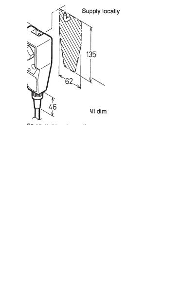
Button-type remote controller FAP-6211/6222
48
(1.9”)
135
(5.3”)
62
(2.44”)
Lever-type remote controller FAP-6221/6222
Allow sufficient space around the unit for maintenance.
82.5-87.5 (3.24”-3.44”)
140
(5.51”)
115
(4.52”) 100
(3.94”)
132
(5.2”)
140
(5.51”)
16
(0.63”)
100
(3.94”)
132
(5.2”)
16
(0.63”)
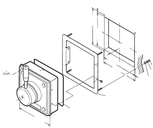
To mount the FAP-6221/6212 in a panel, the optional flush mount kit OP64-4 or OP64-5 is required.
Flush mount kit OP64-4 (Code no. 009-005-790)
Name |
Type |
Code No. |
Qty |
|
|
|
|
Panel frame |
OP64-4 |
009-006-170 |
1 |
Rubber ring |
64-015-4524 |
100-145-111-10 |
1 |
Hex. nut |
M4 |
000-167-488-10 |
4 |
Flat washer |
M4 |
000-167-455-10 |
4 |
Spring washer |
M4 |
000-167-405-10 |
4 |
1-10
1. INSTALLATION
Flush mount kit OP64-5 (Code no. 009-005-800)
Name |
Type |
Code No. |
Qty |
|
|
|
|
Fixing plate |
OP64-5 |
009-006-200 |
1 |
Rubber ring |
64-015-4524 |
100-145-111-10 |
1 |
Hex. nut |
M4 |
000-167-488-10 |
4 |
Spring washer |
M4 |
000-167-405-10 |
4 |
Hex. bolt |
M4x35 |
000-162-861-10 |
4 |
6.5
0.26”
150
(5.9”)
137
(5.4”)
MAX.25(0.98”)
147
(5.8”)
|
|
|
|
|
|
|
|
|
|
|
|
|
|
|
|
|
150 |
|
|
Hex. nut |
|
|
|
|
|
|
|
|
|
|
|
|
|
|
|
|
|
|
|
||
|
|
|
|
|
|
|
|
|
|
|
|
|
|
|
|
|
|
|
||
|
|
|
|
|
|
|
|
|
|
|
|
|
|
|
|
|
|
|
||
|
|
|
|
|
|
|
|
|
|
|
|
|
|
|
|
|
|
|
Spring washer |
|
|
|
|
|
|||||||||||||||||
|
|
|
|
|
|
|
|
|
|
|||||||||||
|
|
|
|
|
|
|
|
|
|
|
|
|
|
|
|
|
|
|
||
|
|
|
|
|
|
|
|
|
|
|
|
|
|
|
|
|
|
|
||
|
|
|
|
|
|
|
|
|
|
|
|
|
|
|
|
|
(5.9”) |
|
|
|
|
|
|
|
|
|
|
|
|
|
|
|
|
|
|
|
|
|
|
||
|
|
|
|
|
|
|
|
|
|
|
|
|
|
|
|
|
|
1.5 |
Flat washer |
|
|
|
|
|
|
|
|
|
|
|
|
|
|
|
|
|
|
|
|
||
|
|
|
|
|
|
|
|
|
|
|
|
|
|
|
|
|
|
|||
|
|
|
|
|
|
|
|
|
|
|
|
|
|
|
|
|
|
|
||
|
|
|
|
|
|
|
|
|
|
|
|
|
|
|
|
|
Panel frame |
(0.06”) |
||
|
|
|
|
|
|
|
|
|
|
|
|
|
|
|
|
|
|
|
|
|
|
|
|
|
|
|
|
|
|
|
|
|
|
|
|
|
|
|
|
|
|
|
|
|
|
|
|
|
|
|
|
|
|
|
|
|
|
|
|
|
|
|
|
|
|
|
|
|
|
|
|
|
|
|
|
|
|
|
|
|
|
|
|
|
|
|
|
|
|
|
|
|
|
|
|
|
|
|
|
|
|
|
|
|
|
|
|
|
|
|
|
|
|
|
|
|
|
|
|
|
|
|
|
|
|
|
|
|
|
|
|
|
|
|
|
|
|
|
|
|
|
|
|
|
|
|
|
|
|
|
|
|
|
|
|
|
|
|
|
|
|
|
|
|
|
|
|
|
|
|
|
|
|
|
|
|
|
|
|
|
|
|
|
|
|
|
|
|
Rubber ring
140
(5.51”)
How to flush mount the FAP-6221 with flush mount kit OP64-4
1-11
1. INSTALLATION
Hex. nut
|
|
|
|
Spring washer |
||||
|
|
|
|
Hex. bolt |
||||
|
|
|
|
|
|
|
|
Pan head screw |
|
|
|
|
|
|
|
|
|
|
|
|
|
|
|
|
|
M3x20 |
Rubber ring |
|
|
|
|
|
|
(local supply) |
|
|
|
|
|
|
Fixing plate |
|||
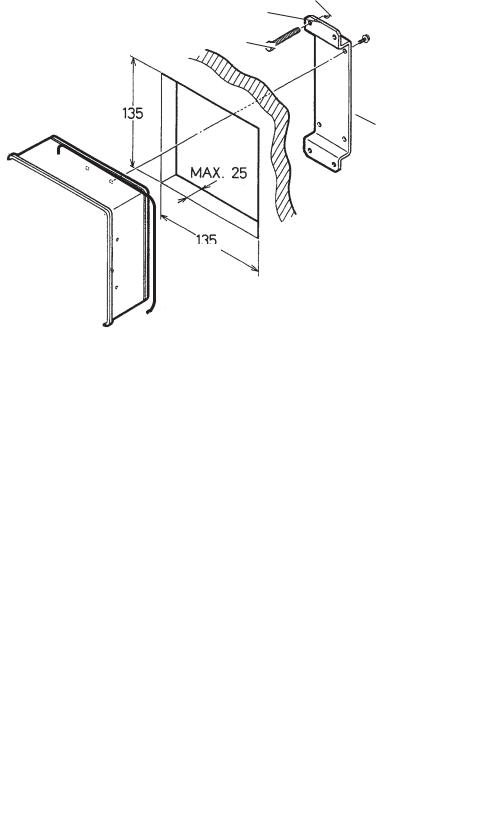
135 |
|
|
|
|||||
|
|
|
|
|
|
|||
|
|
(5.3”) |
|
|
|
|
|
|
|
|
|
|
|
|
|
|
|
|
|
|
|
|
|
|
||
|
|
|
|
|
MAX.25(0.98”) |
|
|
|
135
(5.3”)
How to flush mount the FAP-6221 with flush mount kit OP64-5
1.5Distributor FAP-6800 (option)
Use the Distributor to connect three Non-Follow Up-type remote controllers to the Processor Unit. Fix the unit to the mounting location with wood screws. For added support, use nuts, bolts and washers (all local supply) instead of the wood screws.
60(2.36”)
37(1.46”)
60(2.36”)
8(0.3”)
172(6 |
|
. |
|
|
77”) |
156(6 |
|
|
||
|
||||
|
|
|||
172(6 |
|
. |
|
|
. |
14”) |
|
|
|
|
77”) |
|
|
|
|
|
|
|
|
1-12
1. INSTALLATION
1.6Control Unit FAP-7021
The Handheld Control Unit FAP-7021 can be mounted on the bulkhead or desktop using the cradle.
When selecting a location for the Control Unit, keep the following in mind.
•Mount the unit where shock and vibration are minimal.
•Do not install the display unit under "Plexiglas" or other type of shielding material. Plexiglas can trap heat and moisture or magnify sunlight energy onto the surface of the display.
•Follow the compass safe distances shown in the safety instructions on page i to prevent interference to a magnetic compass.
For the cradle mount, fix the cradle to the mounting location with four self-tapping screws (4x20, supplied), referring to the outline drawing for mounting dimensions. Put the Control Unit in the cradle.
1.7Cable Extension Kit FAP-7822 (option)
The Control Unit FAP-7021 comes with a 10 m cable. If the cable is not long enough, use the Cable Extension Kit FAP-7822, which provides for extension of the cable an additional 10 m.
Type: Cable Extension Kit FAP-7822 Code No.: 001-082-780
Name |
Type |
Code No. |
Qty |
|
|
|
|
Connector fixing box |
64-027-1011-2 |
100-327-882-10 |
1 |
Label |
64-027-1012-1 |
100-327-891-10 |
1 |
Self-tapping screw |
4x20 |
000-158-850-10 |
4 |
Cable |
BD-07PM-07AF-LR-100 |
000-172-016-10 |
1 |
Fix the Connector Fixing Box with four self-tapping screws (4x20, supplied). Refer to the outline drawing for mounting dimensions.
Note 1: When the Control Unit is not connected, attach the terminator (supplied) to the Connector Fixing Box.
Note 2: To connect the extension cable to the Processor Unit, remove the connector.
1-13
1. INSTALLATION
This page is intentionally left blank.
1-14
2.WIRING
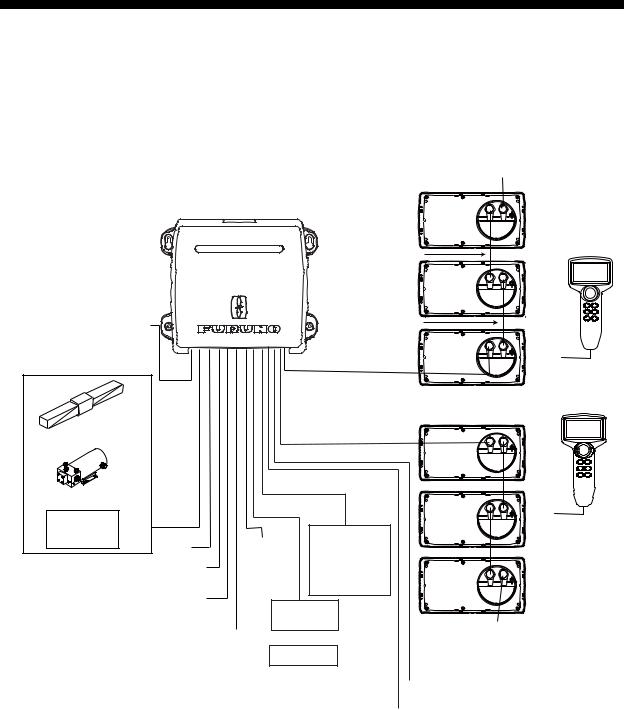
2.1General Wiring
All units are connected to the Processor Unit. Separate the cables as far as possible from the cables that transmit radio frequency or pulsed signals. At least one meter separation is recommended.
|
|
Terminator BD-07AFFM-LR7001*1 |
|
|
||
|
|
|
(supplied) |
|
|
|
PROCESSOR UNIT |
|
|
BD-07AF-07AF-LR-100 |
|
|
|
|
|
|
|
|
|
|
FAP-7002 |
|
|
|
|
|
|
Power supply |
|
|
BD-07AF-07AF-LR-100 |
|
|
|
12-24 VDC |
|
|
|
|
or |
|
Ship Steering System*3 |
|
|
|
|
|
|
|
BD-07AFFM-LR-150 |
|
CONTROL |
|||
|
|
CONTROL UNIT |
|
UNIT |
||
|
|
|
|
|
||
|
|
|
|
FAP-7021 |
||
|
|
|
FAP-7001/7011/7011C |
|
||
Solenoid valve |
|
|
|
|
|
|
|
|
|
|
|
or |
|
Reversible pump |
|
|
|
|
|
|
Hydraulic |
|
|
RUDDER |
|
|
|
linear drive |
Remote |
|
|
|
|
|
PC |
|
REFERENCE |
|
|
|
|
NMEA0183 PORT1 (Nav equip.) |
Controller |
|
UNIT |
|
|
|
or |
|
|
|
|
||
|
|
FAP-6112*2,*3 |
|
|
|
|
NMEA0183 PORT2 |
Distributor |
|
|
|
|
|
Remote |
|
|
|
|||
(IF-700IPS or Nav equip.) |
|
|
|
|||
Controller |
Terminator |
|
||||
|
|
|||||
CANbus (FI-50, PG-700, etc.) |
|
or |
|
|
||
|
|
BD-07AFFM-LR7001*1 |
||||
|
Distributor |
|||||
*1: Attach the terminator to the empty |
(supplied) |
|
||||
|
|
|
|
|||
connector of the last control unit in the series. |
|
Contact signal out |
|
|
||
|
|
|
|
|
||
*2: Not required for Fantum FeedbackTM. |
|
|
Contact signal in |
|
|
|
*3: Not required for the IPS drive.
2-1
2. WIRING
2.2Processor Unit
All cables are connected in the Processor Unit. To connect the FAP-7021 and FAP-6112 to the Processor Unit directly, remove the connector at the end of their cables.
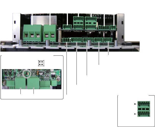
2.2.1Connections inside the processor unit
Pins are “numbered” from left to right, in ascending order. See the inset in the figure below for details.
|
|
|
|
|
TB13 |
||||
|
|
|
|
|
(Remote Controller 1 and 2) |
||||
|
|
|
|
|
|
TB8 |
|||
|
|
|
|
|
|
(Control Unit A and B) |
|||
|
|
TB1 |
|
|
TB11 |
||||
TB2 |
(Power) |
|
|
(CAN bus equipment) |
|||||
|
TB10 |
|
|
|
TB12 |
||||
(Motor/ |
|
|
|
|
|||||
Solenoid) |
|
(RRU*) |
|
|
|
(CAN bus power) |
|||
|
|
|
|
|
|
|
|
|
* Rudder |
|
|
|
|
|
|
|
|
|
|
|
|
|
|
|
|
|
|||
|
|
|
|
|
|
|
|
|
Reference Unit |
|
|
|
|
|
|
|
|
|
|
|
|
|
|
|
|
|
|
|
|
+-
Location of jumper block J104
J104 |
3 |
1 |
||
4 |
2 |
|||
|
|
|||
|
|
|
|
|
TB13 TB8
TB7 (IF-700IPS or
NMEA 0183 Nav equipment)
TB6
(NMEA 0183 Nav equipment)
TB5
(GENERAL IN (Event switch, etc.))
TB4
(GENERAL OUT (External buzzer, etc.))
TB3 |
Pin arrangement |
||
(Bypass clutch) |
Pin no. |
|
|
|
|
|
|
|
|
||
|
1 - 6 |
|
|
|
Pin no. |
|
|
|
|
||
|
7 - 12 |
|
|
(Example: TB13)
2-2
2. WIRING
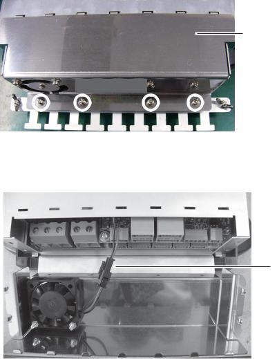
2.2.2How to fasten cables to the cable clamps
Fasten the cables to the processor unit as shown below. There is no specified order to fasten the cables.
1.Remove the outside cover:
1)Hold the right and left sides of the cover.
2)Pull the cover outward and lift to remove.
2.Remove the four screws marked with circles in the figure shown below.
 Shield cover
Cable clamp/fan assy.
3.Separate the cable clamp/fan assy from the shield cover as shown in the figure below. Open the assembly carefully to prevent damage to the cable connected to the fan.
4.Disconnect the fan connector.
Disconnect this connector.
5.Twist cable cores then put the cores into their correct connector blocks. (See the next page for how to put wires into a connector block.)
6.For the NMEA cable, wind vinyl tape around the cable cores.
2-3
2. WIRING
7. Fasten a cable tie (supplied) to a cable and the “clamp leg”.
Connector block


 Drain wire
 Vinyl tape
Braided shield (If your cable doesn't
have a braided shield,  wind the copper tape

around aluminum foil.)
Cable tie
Clamp leg
Cable
8.Connect the fan connector.
9.After you have connected all equipment, fasten the cable clamp/fan assy.
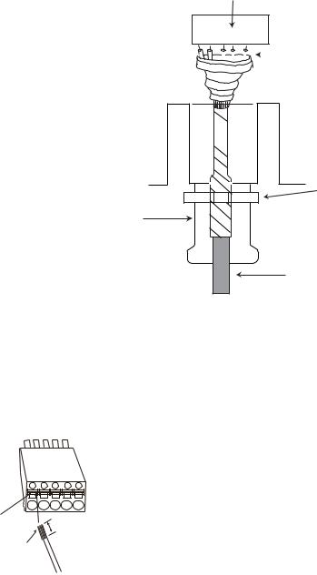
2.2.3How to put wires into the connector blocks
The cables are connected to their connector blocks inside the Processor Unit. Open the unit and put cables into the connector blocks as shown in the figure below.
CONNECTOR
BLOCK
Push |
6 mm |
|
Twist Wire cores.
How to put wire into connector block
1.Remove shield of wire by 6 mm.
2.Twist core.
3.Push spring-loaded catch with slotted-head screwdriver.
4.Insert core into hole.
5.Release screwdriver.
6.Pull wire to confirm it is securely inserted.
Note: To connect two Control Units (to TB8 and TB9), change the position of the jumper block J104 from #1-2 to #3-4. (See the illustration on page 2-2 for location.) For single Control Unit, use TB8 and set J104 at position #1-2.
2-4
2. WIRING
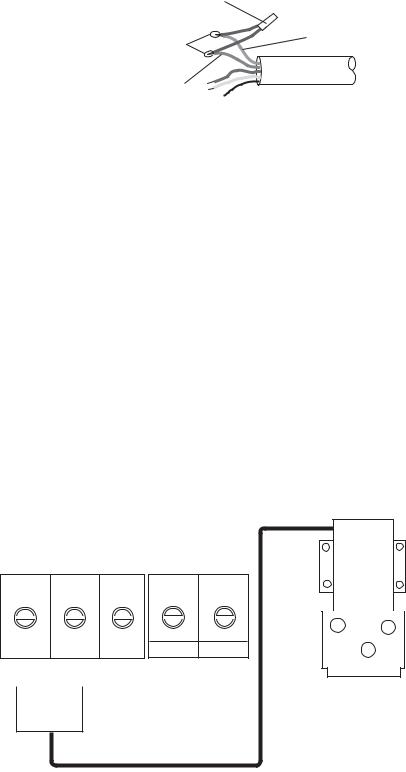
2.2.4How to terminate of NMEA2000 connection
When the termination of NMEA2000 connection is needed in the NAVpilot, attach the resistor assembly (supplied as installation materials) to the NMEA2000 cable in the processor unit.
Twist the lead wire of the resistor assembly to the NMEA2000 cable, and solder them as below.
Resistor assembly
(Type: 120 OHM-1007#24-L50)
White
Twisting and soldering
Blue
NMEA2000 cable
2.2.5Power and motor cables
For the power cable and motor line cable, see the table below to select cables. Connect the power cable to a breaker that has a rating acceptable to the motor.
Rated current |
25 A |
|
10 A |
|
of the motor |
|
|
||
|
|
|
|
|
|
|
|
|
|
Cable length |
Section of core(mm2) |
AWG |
Section of core(mm2) |
AWG |
3 m or less |
2.5 |
12 |
1.0 |
16 |
6 m or less |
4 |
10 |
1.25 |
16 |
10 m or less |
6 |
8 |
2 |
14 |
|
|
|
|
|
16 m or less |
10 |
6 |
4 |
10 |
•The thickness of the cables varies with the rated current of the motor. The table shows the specifications for 10 or 25 A motor.
•Use single core wire or stranded wire. (For stranded wire the max. no of wires is seven).
•Do not twist cores to prevent them from disconnecting.
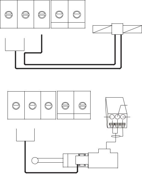
How to connect a reversible pump
TB2 |
TB1 |
MOTOR A+ MOTOR B- GND POWER + POWER -
SOL A SOL B
Reversible pump
2-5
2. WIRING
How to connect a solenoid drive
TB2 |
TB1 |
Solenoid valve
MOTOR A+ MOTOR B- GND POWER + POWER - SOL A SOL B
Solenoid Solenoid
GND motor
How to connect a hydraulic linear drive
TB2 |
TB1 |
TB3
|
B/C |
|
1 2 3 |
PWR+ |
SHIELD |
MOTOR A+ MOTOR B- GND POWER + POWER -
SOL A SOL B
Hydraulic linear drive
2-6
2. WIRING
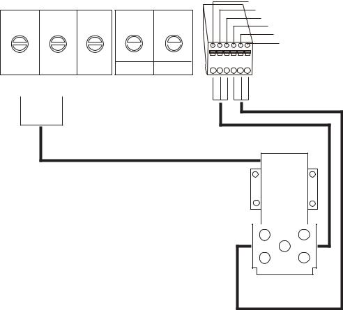
How to connect the Accu-Steer FPS 12V/24V helm sensor
TB2 |
TB1 |
TB5 |
Brown |
|
|||
|
|
|
Black |
|
|
|
Blue |
|
|
|
Brown |
|
|
|
Black |
|
|
|
Blue |
MOTOR A+ MOTOR B- GND |
POWER + POWER - |
|
|
SOL A SOL B |
|
|
|
Accu-Steer FPS |
12V/24V |
2.2.6Teleflex linear sensor
To connect a Teleflex linear sensor AR4502 (instead of the FAP-6112), do the following modification.
1.Make the cable connection as shown below. Refer to the installation manual of the linear sensor for recommended cable.
PROCESSOR |
TB10 |
|
|
||
UNIT |
|
1 |
|
RED |
|
|
|
|
WHT |
LINEAR SENSOR |
|
|
|
2 |
|
||
|
|
|
|
||
SPU Board |
|
3 |
|
BLK |
AR4502 |
(64P1158) |
|
4 |
|
|
|
|
|
|
|
||
|
|
5 |
|
|
|
|
|
|
|
|
|
|
|
|
|
|
|
Wind tape where shield was removed.
2.Set the RRU type to [LINEAR SENSOR] on the [DOCKSIDE SETUP] menu when you do the initial settings, in the next chapter.
2-7
2. WIRING
2.2.7CAN bus power
The maximum current that can be supplied to the CAN bus network is 1A. Use a “floating power supply” and make sure it meets with CAN bus (NMEA 2000) regulations.
For complete information about CAN bus wiring, see the “Furuno CAN bus Network Design Guide (TIE-00170-*)” on Tech-Net.
2.2.8Connection to TB4
TB4 is for contact relay output. The No.1 line is Normal Open, and the No.3 line is Normal Close. For Active Close, use Normal Open; for Active Open use Normal Close. The rated current of the contact is 3A. The maximum acceptable open-close is 50VA.
2.3Control Unit
Note: For how to connect the Control Unit FAP-7011C with the Processor Unit FAP-7002, see the operator’s manual (OME-72780).
FAP-7001/FAP-7011
A maximum of six Control Units can be connected. The Processor Unit has two ports for connection of two main Control Units, and two Control Units can be connected in series to each main Control Unit.
Use the cable BD-07AFFM-LR-150 (supplied) to connect the Control Unit and Processor Unit, and use cable BD-07AF-07AF-LR-100 (optional supply) to connect two Control Units.
FAP-7021
A maximum of two Control Units can be connected. Use the cable attached to the Control Unit (10 m) to connect the Control Unit to the Processor Unit. To increase the length, use the optional Cable Extension Kit.
Notes on connection of Control Units
•Attach the terminator BD-07AFFM-LR7001 to the port not used on the last Control Unit in the series.
•To connect a single Control Unit, use TB8.
•The total length of cables in a series must be within 35 m.
2-8
Loading...